Bilibili video: https://www.bilibili.com/video/BV1BjY1evEhP/ I. Problem
The original PDF file is attached.
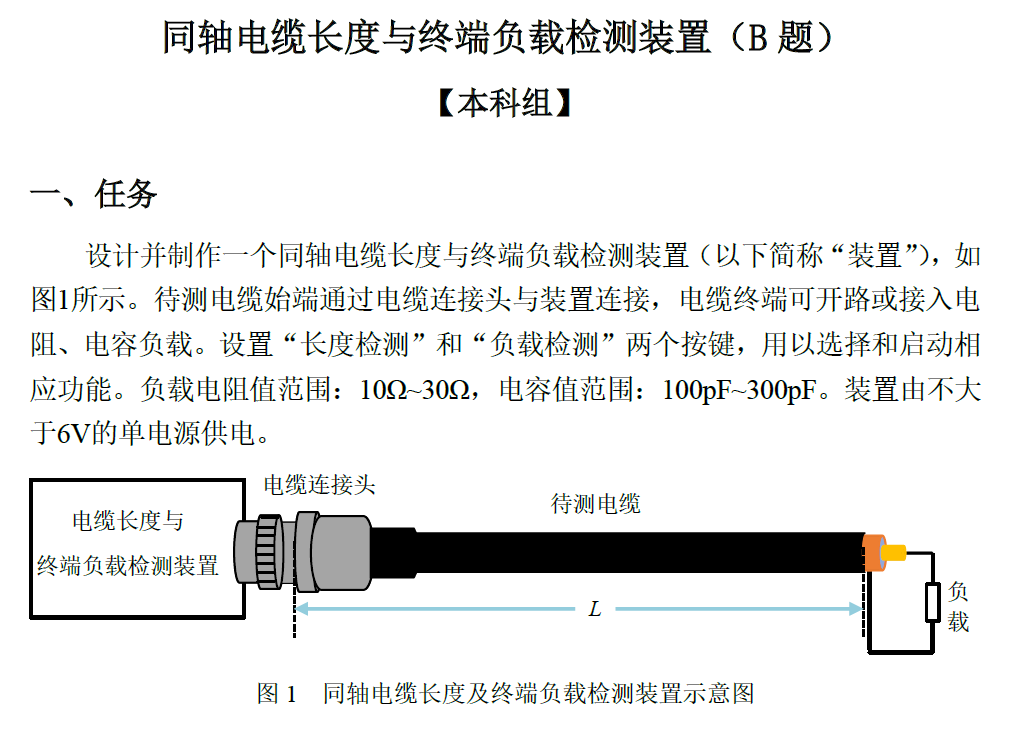
II. Quick Start
Material Preparation:
JLCPCB PCB Ordering: The PCB for this project can be ordered directly without modification. Component Ordering: Components are standardized and can be ordered directly, but a quick check is still necessary. There are two length measurement schemes for this project. The program defaults to Scheme 2, so you don't need to order the relevant components for Scheme 1. For the cable
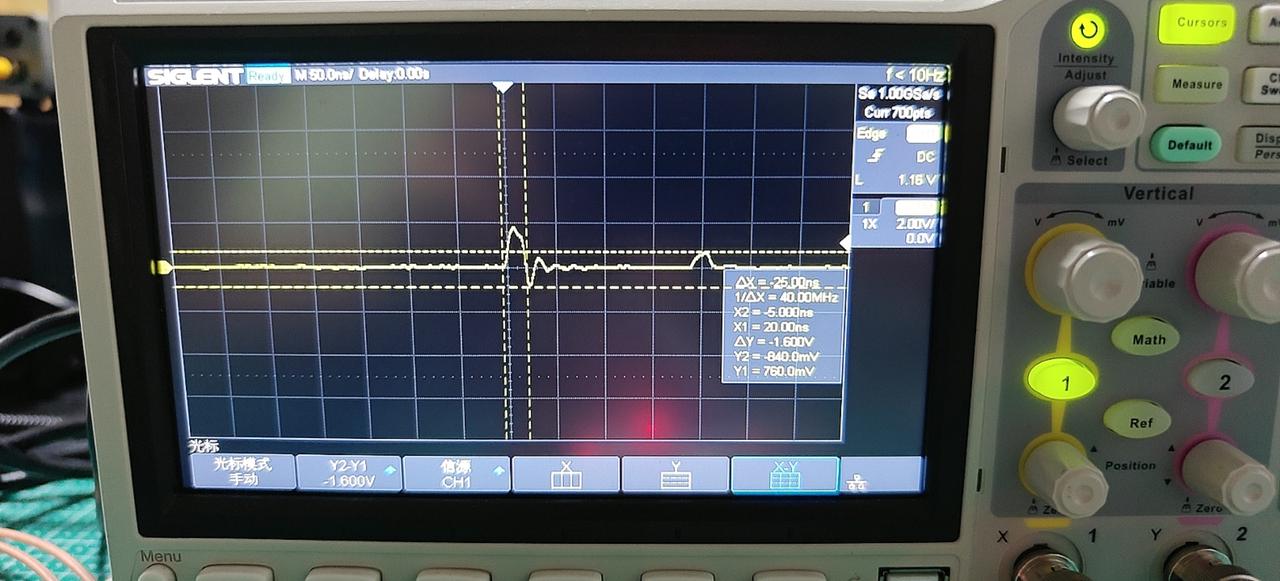
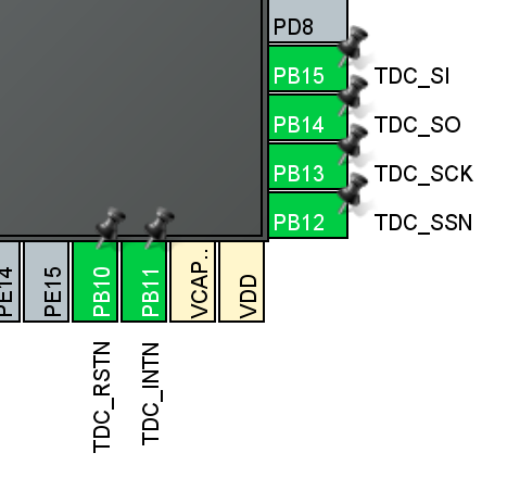
under test and load , we recommend buying RG316 coaxial cable, as the program calibration defaults to this cable. For the load, you can buy a standard calibration load, or buy an SMA connector + through-hole resistor and capacitor and solder them on yourself. PCB Soldering : There are two length measurement schemes for this project. The program defaults to Scheme 2, so you don't need to solder the relevant components for Scheme 1. Program Burning: The attached .bin/.hex files can be burned using STM32CubeProgrammer for quick replication. If you are developing this project, please refer to the attached "CLion STM32 Development Environment Setup" to set up the development environment. When testing the load, it is recommended to solder an SMA female connector onto the coaxial cable and then solder the load onto the SMA male connector for easy load replacement. III. Hardware and Software Design Introduction This problem requires measuring the length of a coaxial cable and the terminal load (resistance and capacitance), with the length measured first, followed by the load. The length, capacitance, and resistance measurement schemes are described below. Length Measurement Scheme: Two methods are available. These are switched via macro definitions in User/user.c, with Scheme 2 used by default. Length Measurement Scheme 1: TDR (Time Domain Reflectometry) Hardware Scheme The problem requires testing the length with the terminal open. If a short pulse is input from the measuring end, the pulse will be reflected at the terminal, as shown in the diagram. This scheme uses a microcontroller to toggle GPIOs to generate a short pulse. The pulse width is shown in the diagram. The microcontroller's GPIO driving capability is insufficient, specifically because the GPIO has a large internal resistance, while the cable has parasitic capacitance and resistance. Parasitic capacitance forms an RC low-pass system, causing a longer pulse rise time; parasitic resistance causes amplitude attenuation. A 74AHC1G14, a NOT gate chip, is used as the driver. According to the datasheet, the rise time is approximately 10ns when powered by 3.3V. The generated pulse, after entering the cable, will be reflected at the cable termination, but the amplitude will be halved or even smaller. For example, if a 3.3V pulse is input into the cable, the resulting reflected pulse will be less than 1.65V. Here, we use a TLV3501 high-speed comparator for pulse shaping to facilitate further processing. According to the datasheet, the TLV3501 achieves a propagation delay of 4.5ns and a rise time of 1.5ns. The following figure shows the original reflected waveform and the waveform after shaping by the TLV3501. Next, we need to measure the time difference between the reflected pulse and the excitation pulse. This requires very accurate measurement; approximately a 10ns time difference corresponds to 1 meter. Here, we use the TDC-GP22 chip to measure the time difference. The TDC-GP22 internally measures minute time differences through gate circuit delays, achieving a resolution of 45ps, thus achieving a length resolution better than 1cm. The TDC-GP22 chip uses the SPI protocol for configuration. After starting the measurement, it receives pulses from the START and STOP pins and calculates the time difference according to the user's configuration. Once the measurement is complete, it notifies the microcontroller via the INTN interrupt pin and then reads the measurement result via SPI. The chip's peripheral circuitry is shown in the diagram below, requiring both 4MHz and 32.768kHz crystal oscillators. The 4MHz crystal oscillator is used to calibrate the logic gate delay (because logic gate delay is easily affected by temperature), and the 32.768kHz crystal oscillator is used to calibrate the 4MHz crystal oscillator (the 32.768kHz crystal oscillator is more accurate than the 4MHz crystal oscillator). The program generates pulses by toggling GPIO levels. To shorten the pulse width, the program writes to registers, as shown in the code below: `PULSE_GPIO_Port->BSRR = (uint32_t)PULSE_Pin` ` PULSE_GPIO_Port->BSRR = PULSE_Pin; // Set, 1` The TDC-GP22 driver configures the TDC-GP22 by writing to registers via the SPI protocol. The registers of this chip are quite complex; specific functions should be checked in the datasheet. Here, we briefly list the register configurations and functions for this project. A detailed configuration can also be found in the attached Excel spreadsheet. Register address values and their functions : 0x80 0x009620 Measurement range 1, 4M crystal oscillator frequency divider, 4M crystal oscillator oscillates continuously after power-on, automatic calibration, calibration time is 8 32K cycles, START and STOP rising edge sensitive. 0x81 0x014100 Time difference calculation method: first pulse of STOP1 minus first pulse of START. 0x82 0xE00000 Enable all interrupt sources, START and STOP single edge sensitive. 0x83 0x180000 Almost all default values . 0x84 0x200000 All default values. 0x85 0x080000 Noise unit disabled. 0x86 0x010000 Measurement resolution doubled from 90ps to 45ps. TDC-GP22 connection pins to microcontroller are as follows: Microcontroller pins TDC-GP22 pin functions : PB15 MISO SPI master transmit, slave receive. PB14 MISO SPI master receive, slave transmit. PB13 SCK SPI clock PB12 SSN SPI slave select, active low PB11 INTN TDC interrupt signal issued, active low


The PB10
RSTN
TDC reset is active low.
The program uses software SPI to configure the TDC-GP22. See User/Drivers/tdc.h and User/Drivers/tdc.c for details.
The TDC_Config() function is responsible for configuring the registers. Modify this function if you want to implement other measurement functions.
If you have modified the pin configuration or migrated the microcontroller platform, please modify the macro definitions and functions at the beginning of the User/Drivers/tdc.c file. The relevant business logic
for
length measurement is in User/getL.h and User/getL.c, including calibration parameters, unit conversion, and averaging of multiple measurements.
It is recommended to recalibrate the following parameters
: Coaxial cable speed factor: The speed of light in the cable is slower than the speed of light in a vacuum. This is the ratio to the speed of light in a vacuum, generally around 70%
. Length compensation: Compensation when the length of the cable under test is 0 cm.
#define SPEED_FACTOR 0.6997f // Coaxial cable speed factor
#define BIAS_LENGTH 23.178f // Length compensation
Length measurement scheme two: NE555 capacitance measurement
method hardware scheme
The parasitic capacitance of coaxial cables is relatively stable with length. According to the datasheet, the parasitic capacitance of the RG316 coaxial cable is 96.45pF/m.

Therefore, the length of the coaxial cable can be indirectly measured by measuring the capacitance. The NE555 oscillating circuit is a good capacitance measurement scheme.
The following diagram shows a typical NE555 square wave generator circuit:
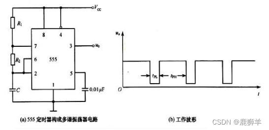
the frequency of the square wave it generates is related to the values of the resistors and capacitors, as shown in the formula below.
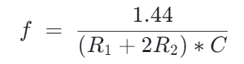
If we fix resistors R1 and R2 and replace capacitor C with the capacitor to be measured, we can indirectly measure the capacitance through frequency. This method can achieve a measurement accuracy better than 1pF.
In this project, R1 = 10kΩ and R2 = 1MΩ are selected.
The program implements
the microcontroller to capture and measure the external square wave signal using a timer input. Here, TIM2 is chosen because its counter is 32-bit, which is convenient for processing.
Interrupts are enabled, and the GPIO pull-down resistors are turned on.
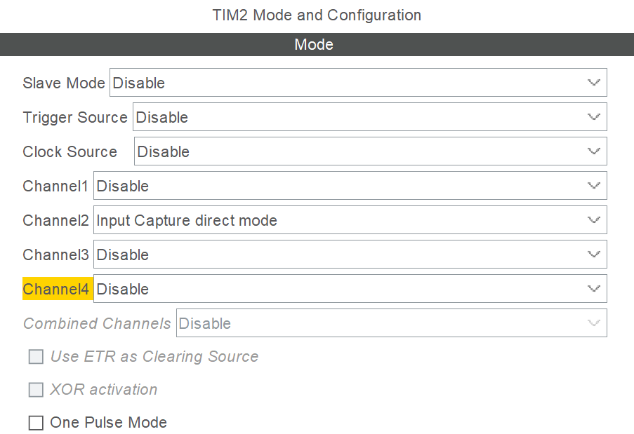

Each time the rising edge of the external signal arrives, the interrupt callback function is entered. In the callback function, the timer count value CNT is read, and the frequency of the external signal can be obtained. The relevant code is in User/getC.h and User/getC.c, and the relevant calibration parameters are also contained therein.
It is recommended to recalibrate the following parameters to measure multiple sets of data and perform linear fitting using tools such as Excel.
#define C_K 0.977f // Capacitor ratio compensation, error source: inaccurate resistance value of the NE555 resonant circuit
#define C_BIAS_PF (-13.9f) // Capacitor compensation, error source: parasitic capacitance within the device
Capacitor load measurement scheme: NE555 resonant method
(see above for details): Length measurement scheme two: NE555 capacitance measurement method
. According to the requirements of the question, the length is measured first, then the load. The capacitance measured here is actually the total capacitance of the load and the cable parasitic capacitance (parallel capacitance), which needs to be subtracted from the cable parasitic capacitance.
If the TDR scheme was selected for the length measurement earlier, the cable parasitic capacitance needs to be measured discreetly.
Resistance load measurement scheme: Simple voltage divider method
. A simple voltage divider method is used, employing a 51Ω resistor for voltage division, and the ADC of the microcontroller is used to read the voltage division value.
The capacitance measured here is actually the total resistance (series resistance) of the load resistance and the cable parasitic resistance. The cable parasitic resistance needs to be subtracted; it is approximately 0.14 Ω/m.
The relevant business code is in User/getR.h and User/getR.c, and the calibration parameters are also found there.
It is recommended to recalibrate the following parameters:
#define R_K 0.988f // Resistance ratio compensation, error source: inaccurate voltage divider resistor value
#define R_BIAS (-0.25f) // Resistance compensation, error source: parasitic resistance within the device
#define CABLE_R_PER_M 0.14f // Wire parasitic resistance, unit: Ω/m
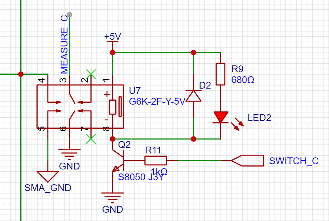
Miscellaneous
measurement item switching
uses signal relay switching: length measurement, capacitance measurement, resistance measurement
Load type judgment
1. First measure the resistance, if it meets the range, output display (<1000Ω)
2. Then measure the capacitance, if it meets the range, output display (>10pF)
3. If neither meets the range, it is considered an open circuit
OLED display
uses Baud rhythm OLED library and model extraction assistant: https://led.baud-dance.com/
Related code is in User/Drivers/oled.h User/Drivers/oled.c User/Drivers/font.h The OLED library in User/Drivers/font.c
does not contain all Chinese characters. If you add new Chinese characters, please use the Porter Rhythm Imaging Assistant to enter them into font.c.
This project uses 12x12 dot matrix characters
. IV. Test Effect Indicators
Measurement Range and Accuracy
Item
Range
Accuracy
Length
0cm ~ 100m
Resolution 0.1cm, error less than 1cm
Resistance
10pF ~ 100nF
Resolution 0.1pF, error less than 1pF
Capacitor
0Ω ~ 1000Ω
Resolution 0.1Ω, error less than 1Ω
Actual Measurement Data
Length
Actual Value
Device Measurement Value
Relative Error
1949cm
1948.99cm
0.00%
1550cm
1549.73cm
0.02%
1050cm
1049.98cm
0.00%
190cm
189.81cm
0.10%
90cm
90.04cm
0.04%
50cm
49.96cm
0.08%
30cm
30.02cm
0.07%
20cm
19.94cm
0.30%
10cm
10.01cm
0.10% Actual
Resistance Value | Relative Error of Device Measurement 19.9986Ω 19.961Ω 0.19% 9.9751Ω 9.964Ω 0.11% Actual Capacitance Value | Relative Error of Device Measurement 203.672pF 203.15pF 0.26% 101.381pF 101.54pF 0.16%


 京公网安备 11010802033920号

 TDC1044AR4C


