For students who have participated in college electronic design competitions, OpenMV must be familiar to everyone. Of course, I was also a child who experienced those four days and three nights of sleepless nights. Although I have never done OpenMV questions, but it looked like it was very fun, and I wanted to get one in school to study (I didn’t get it hhh)... So I wanted to buy one for fun a while ago, but the result was... Look at more than 500...This, this, this, this, this, this, this, this, this, this, this, this, this, this will directly cause a family that is not already wealthy to suffer even worse... But I remember that OpenMV seems to be open source, why should I buy it? Making one myself can solve the problem of worsening the situation ( There is still enough heat to eat hot pot), but if you use open source files directly, I heard that some components are not available (such as the camera base plate), and it is still a 4-layer board (well, the budget is not enough).
1. Introduction to OpenMV 4:
The OpenMV project creates a low-cost, scalable, Python-enabled machine vision module. This module aims to become the " Arduino of the machine vision world ." OpenMV is equipped with a MicroPython interpreter, which allows you to use Python for embedded programming ( Python 3 to be precise). Python makes programming machine vision algorithms much simpler. For example, by directly calling the find_blobs() method , you can get a list containing information about all color blocks. Using python to traverse each color block, you can get all their information, and this only requires two lines of code!
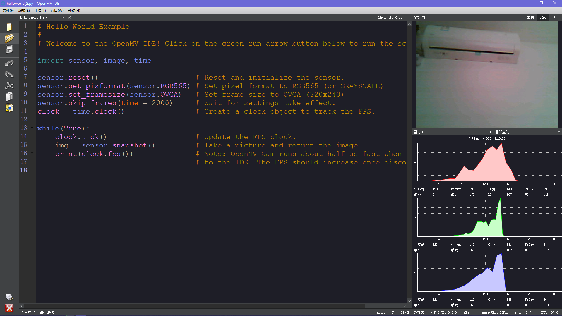
Moreover, you can use the OpenMV-specific IDE, which has automatic prompts, code highlighting, an image window to directly see the camera image, a terminal for debugging, and a histogram containing image information!
2. Schematic diagram:
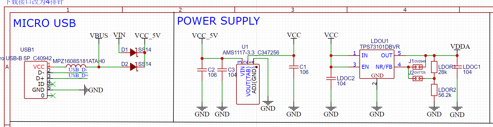
2.1 Power supply
The power input interface I chose is MicroUSB, with magnetic beads ( 180Ω/100MHZ to prevent high-frequency interference) and anti-reverse connection protection (officially MOS, simply use SS14 diodes ). In the circuit, the microcontroller requires 3.3V, and the camera requires 1.8 V, so I used AMS1117 and TPS73101DBVR respectively to generate the voltage required by the circuit.
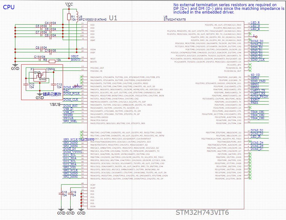
2.2CPU
The CPU is STM32H743VIT6 . It is actually a more advanced STM32 and can be used as an ordinary microcontroller. I just flashed the firmware and turned it into OpenMV . What should be noted here is that the VBUS pin must be connected to the USB power supply, otherwise communication will not be possible .
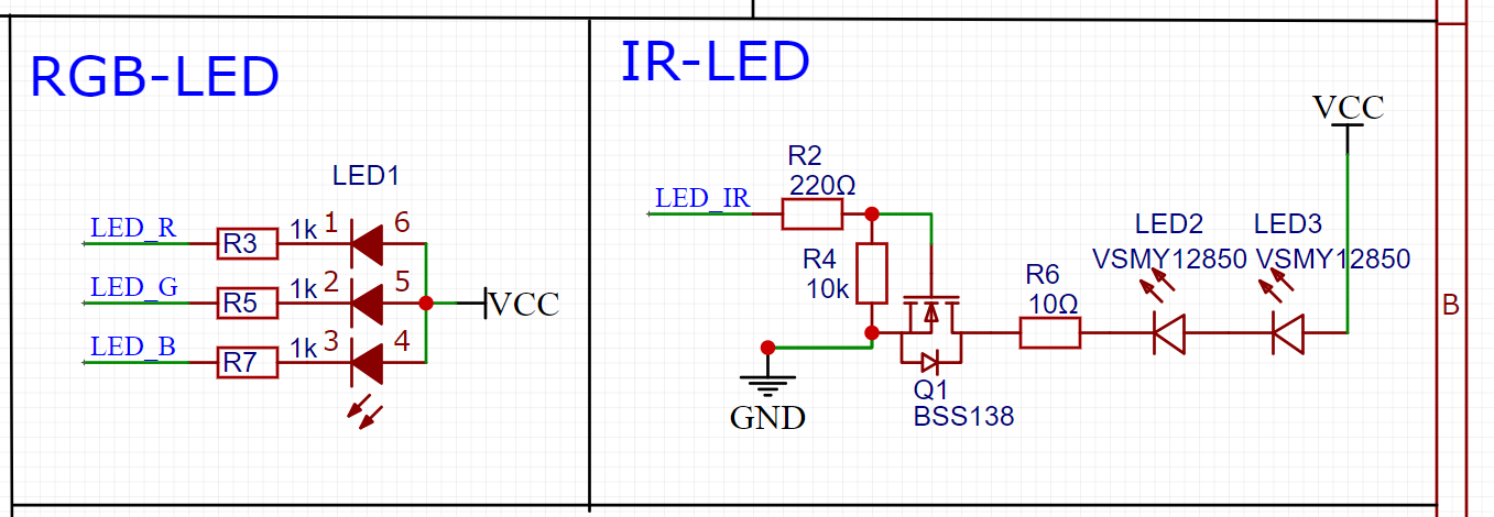
2.3LED
OpenMV has an RGB full-color LED on board to indicate status, and two infrared LEDs, which should be used at night. I haven't tried it yet.
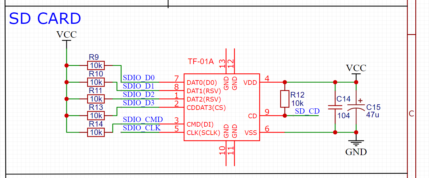
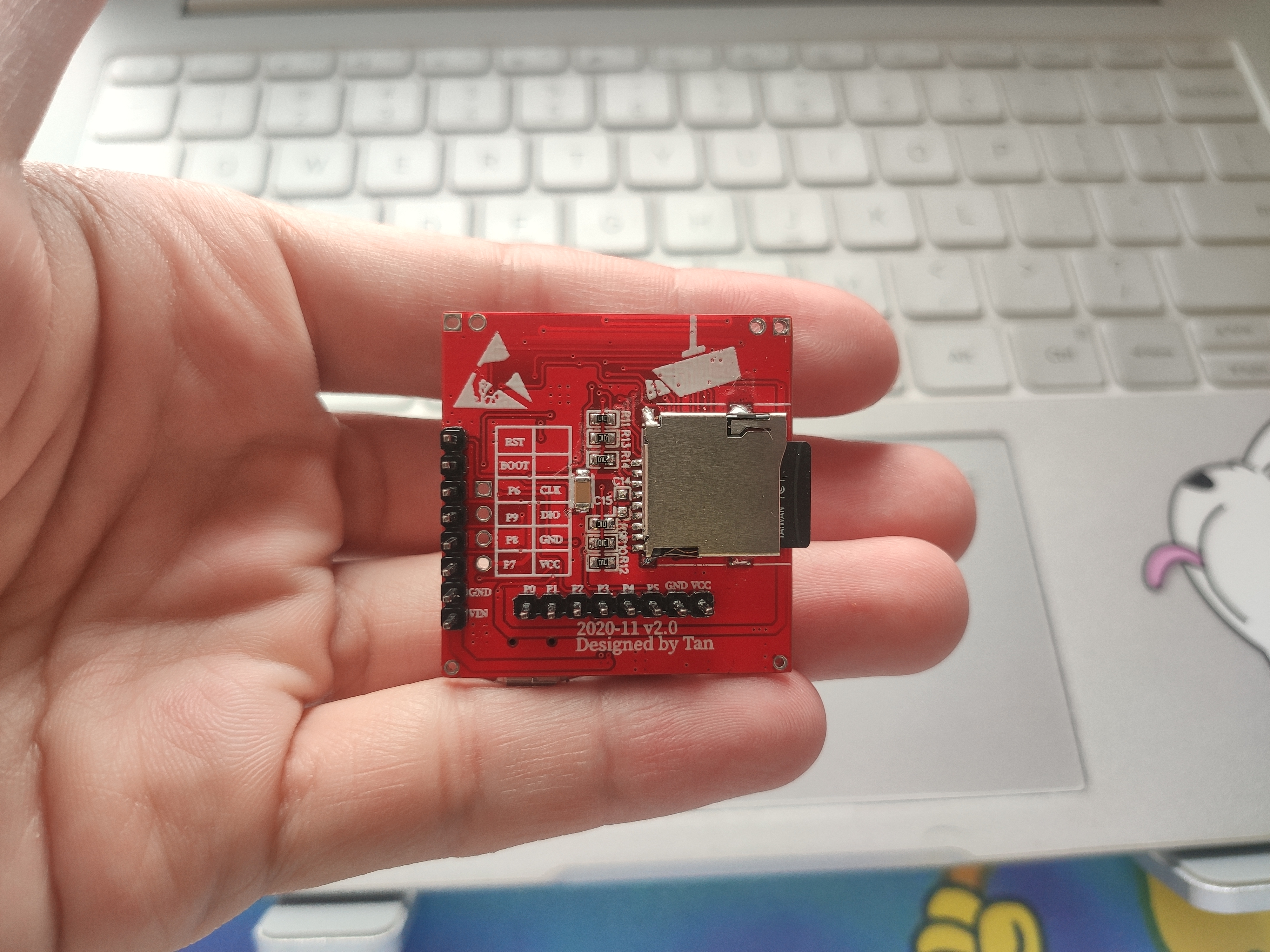
2.4 SD card slot
The SD card requires a filter capacitor and a pull-up resistor for the data pin.
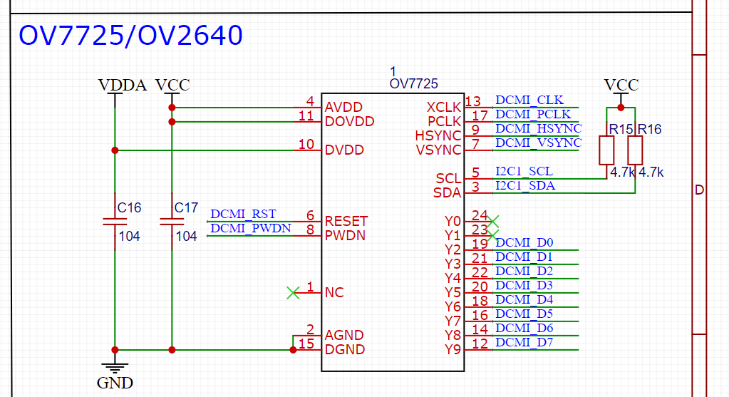
2.5OV7725
The circuit supports OV7725 and OV2640. I chose the OV7725 and haven't tested the other model yet. It should be noted here that the IIC must have two pull-up resistors, otherwise the camera initialization configuration will fail.
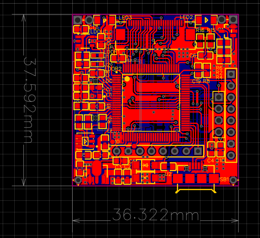
3.PCB
 |
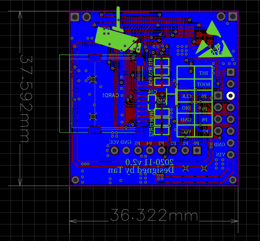 |
| top layer | Ground floor |
4. Flash firmware
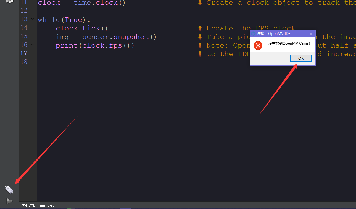
After proofing and welding, the firmware must be flashed before MicroPython programming can be performed. There are 3 methods to flash firmware.
 |
||
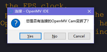
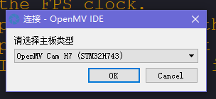
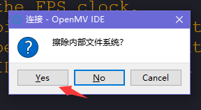
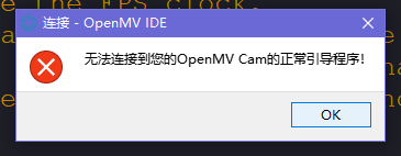
| Plug OpenMV into the computer, open OpenMV IDE and click Connect. It will prompt that it is not found. | ||
 |
 |
 |
 |
 |
 |
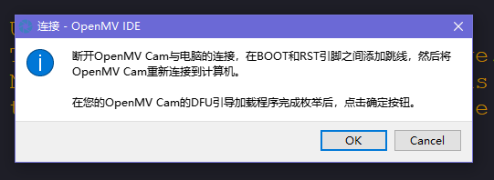 |
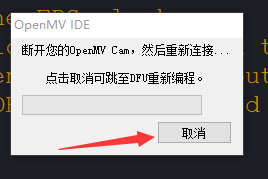
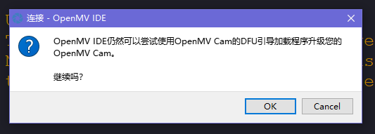
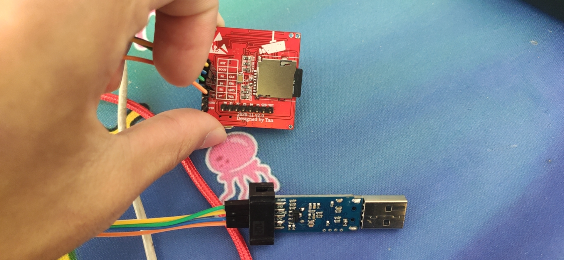
? After you get here, pull out the OpenMV, use tweezers to connect BOOT to the RST pin 3.3v pin and plug it into the computer, and just wait ? | 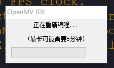 |
First connect the BOOT pin of OpenMV to the RST or 3.3v pin and insert it into the computer.

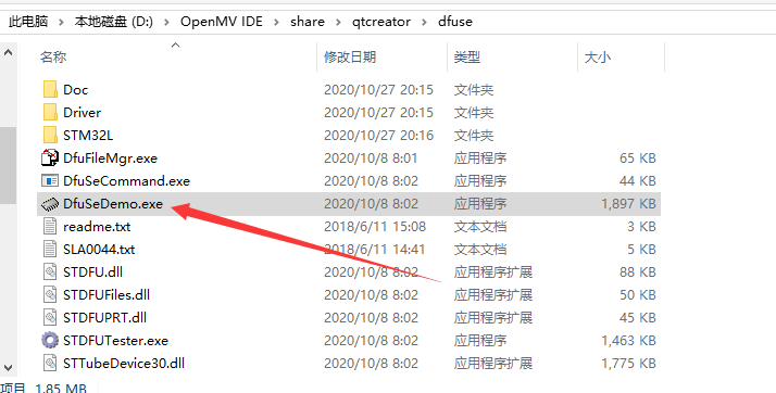
Then enter the OpenMV IDE installation directory D:\ OpenMV IDE\share\qtcreator\dfuse and open DfuSeDemo.exe
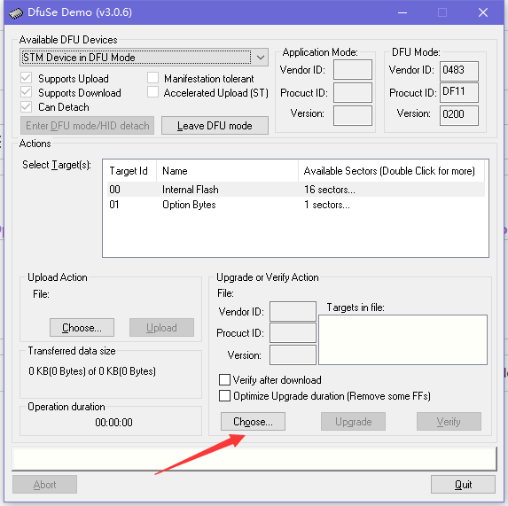
The software will read the ID of the microcontroller, and then click Choose on the right
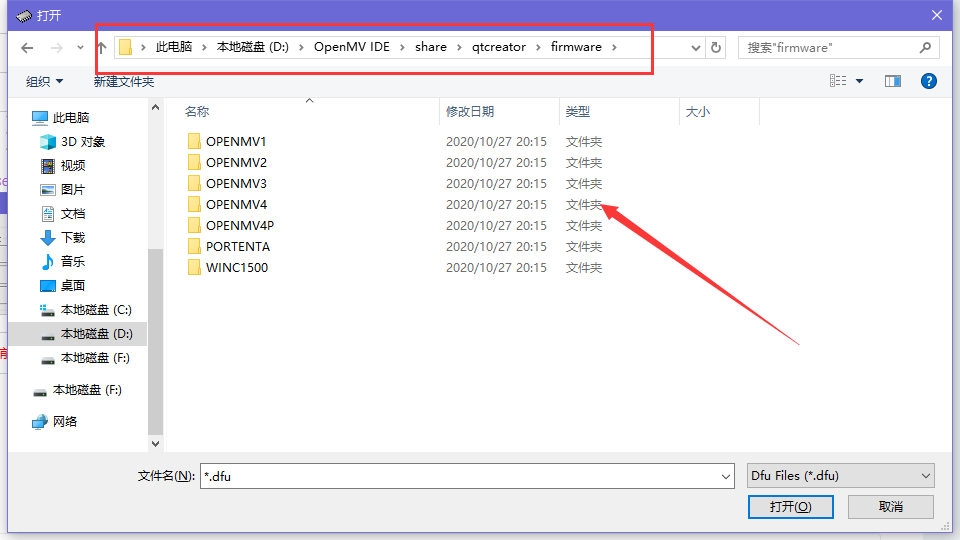
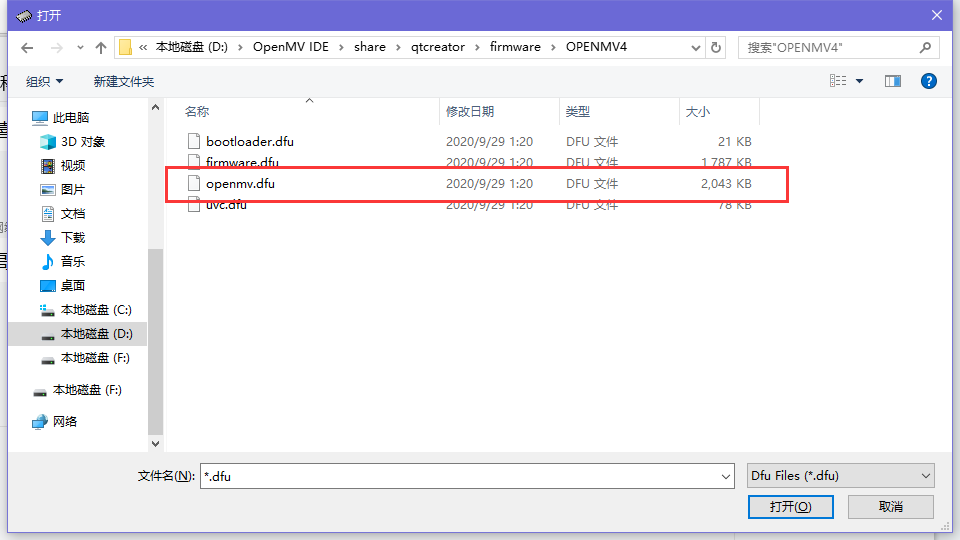
Then select the dfu file path. We are OpenMV4 here, so select the OpenMV4 folder, open OpenMV4.dfu and download it.
The third type is the simplest and crudest. Since it is an STM32 microcontroller, we will directly use the STM32 ST-LINK Utility to burn the bin firmware. Start:
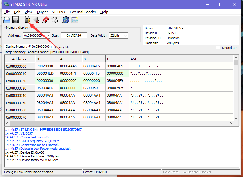
First install the STM32 ST-LINK Utility and then open it, use the ST-Link to connect the debugging interface on the board and plug it into the computer
Open ST-LINK Utility and click the connect button. The picture below shows that the connection has been successful.
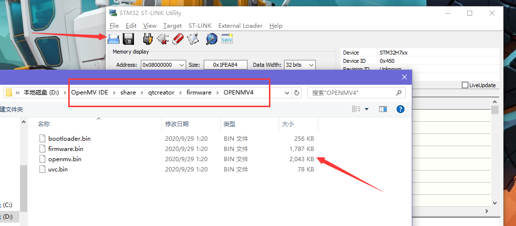
Then click to open the file, and then select the OPENMV4.bin file in the path D:\ OpenMV IDE\share\qtcreator\firmware\OPENMV4
Click download again
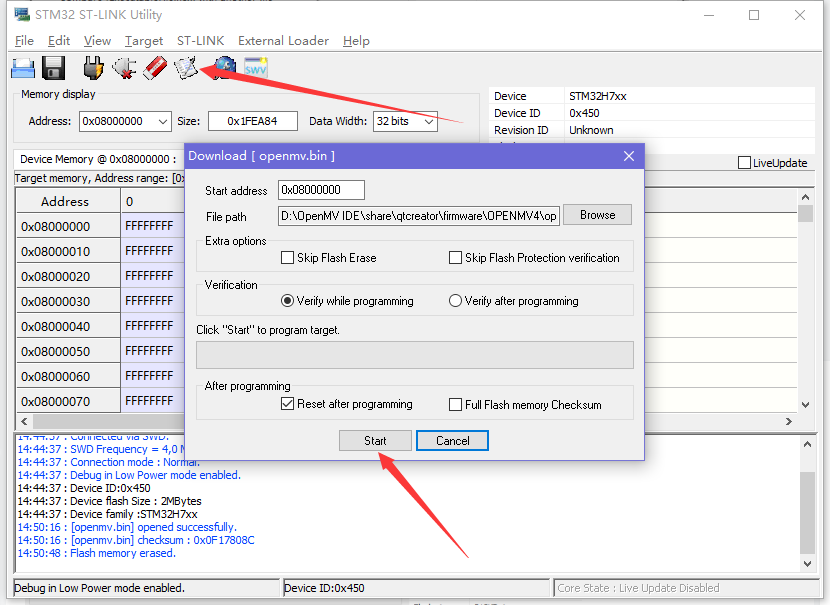
After the download is successful, it will prompt OK
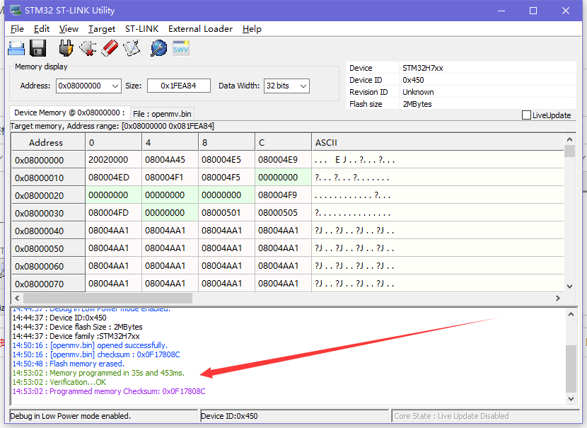
Now that the firmware has been downloaded, you can start playing happily!
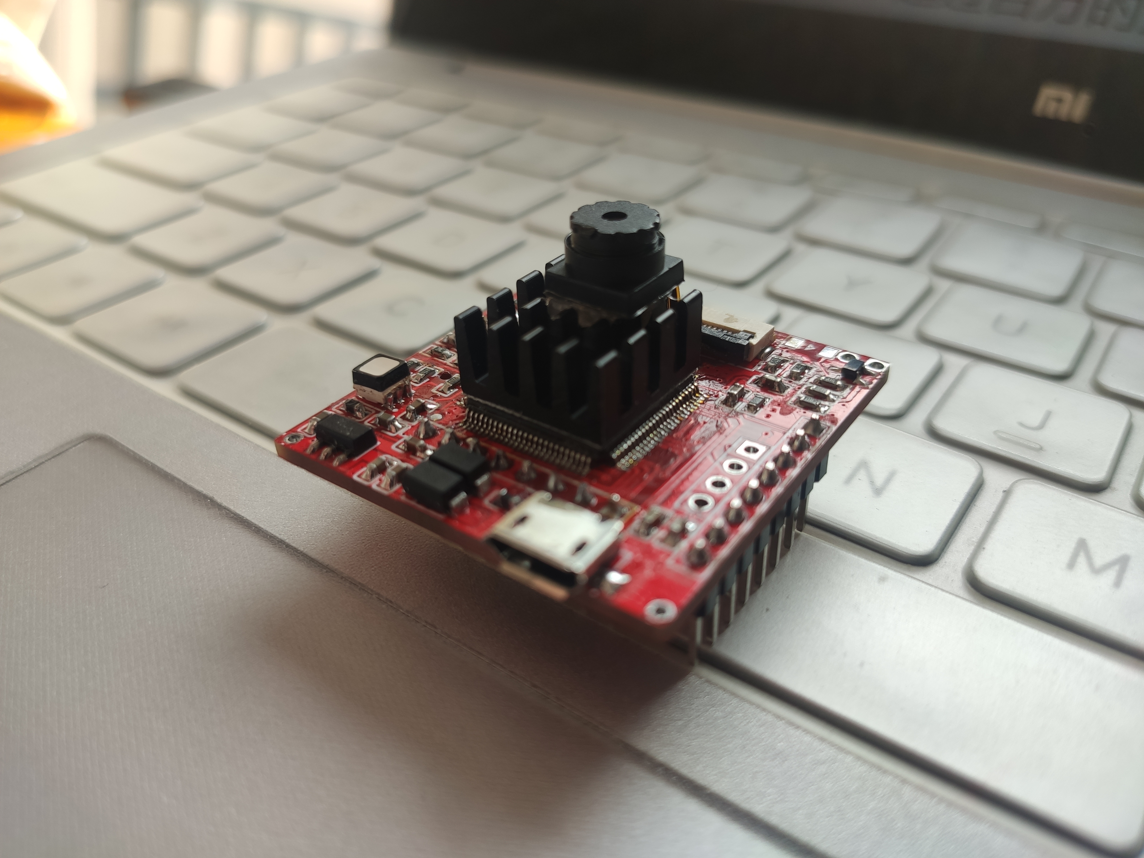
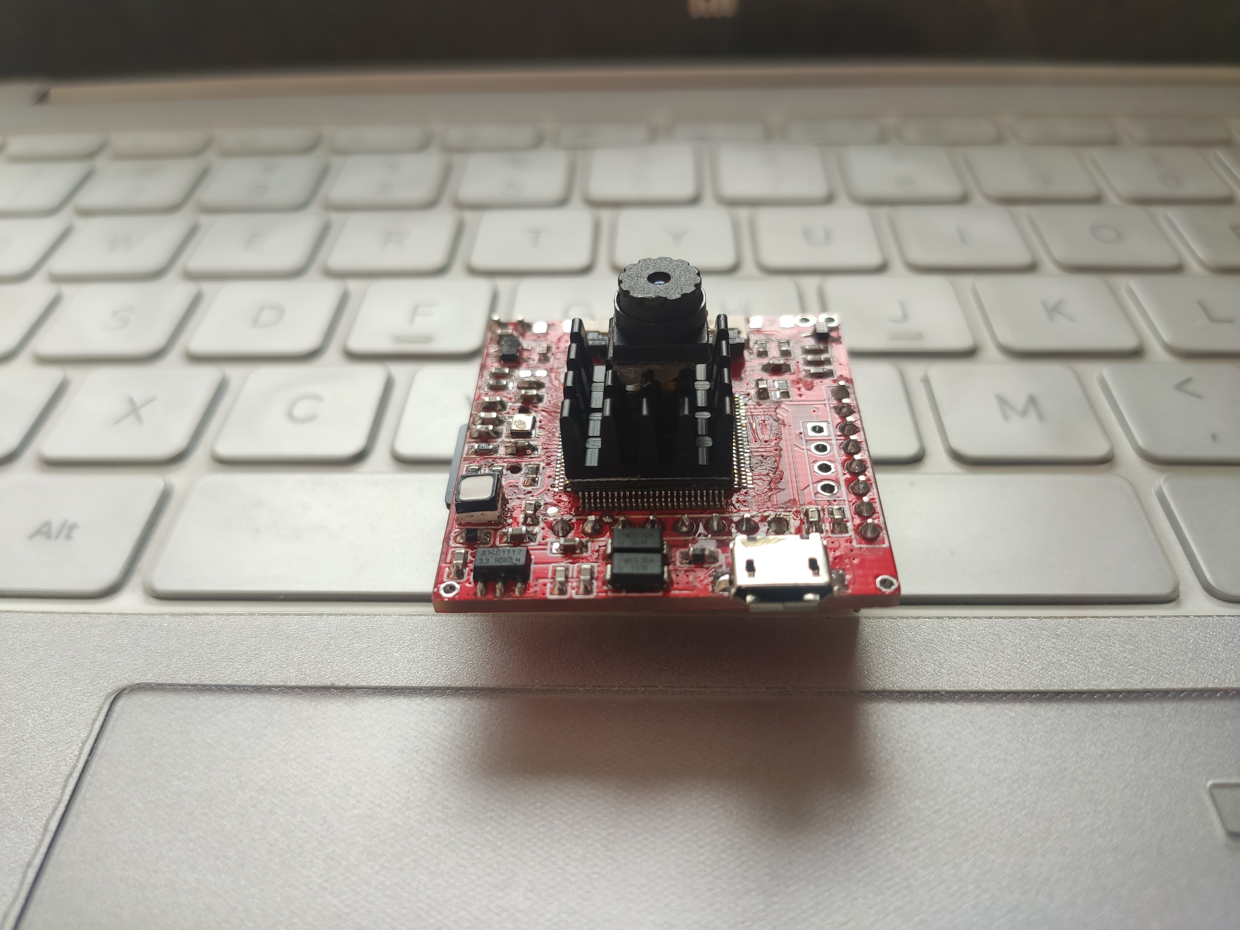
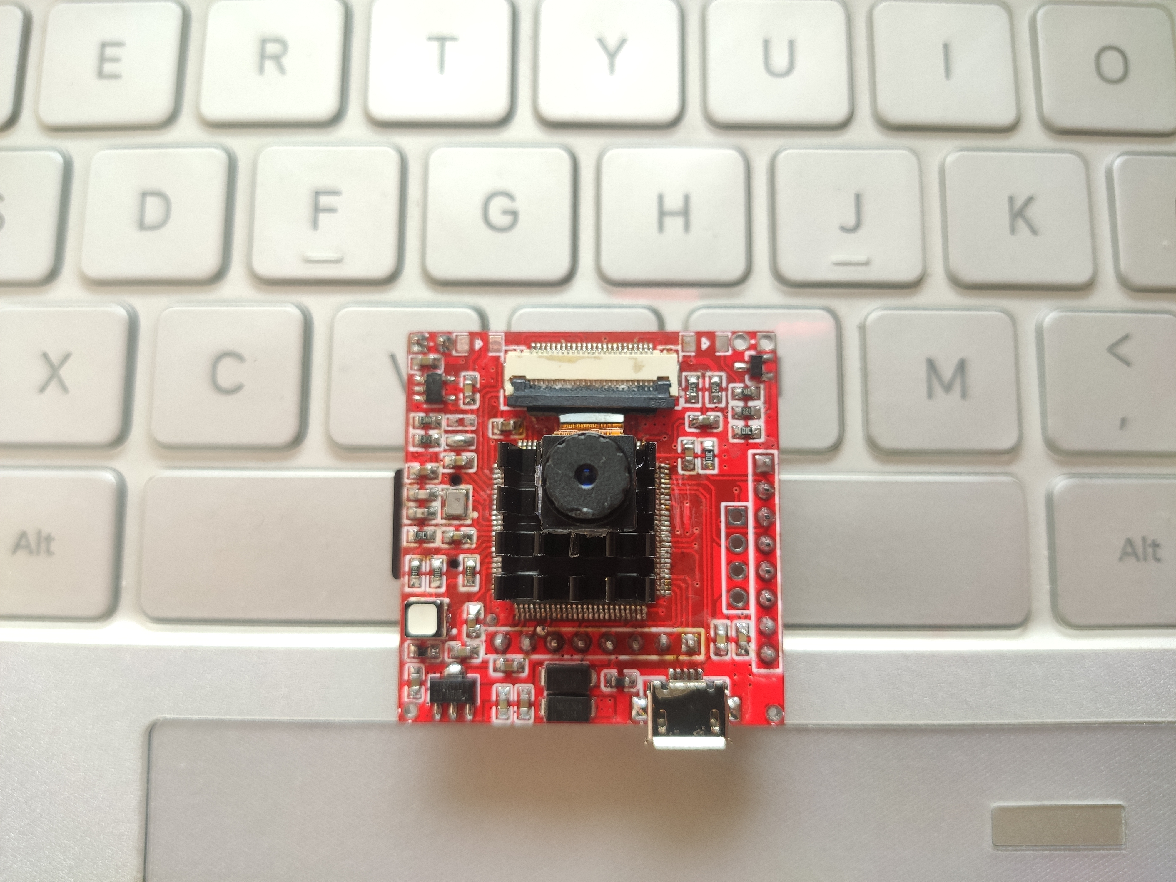
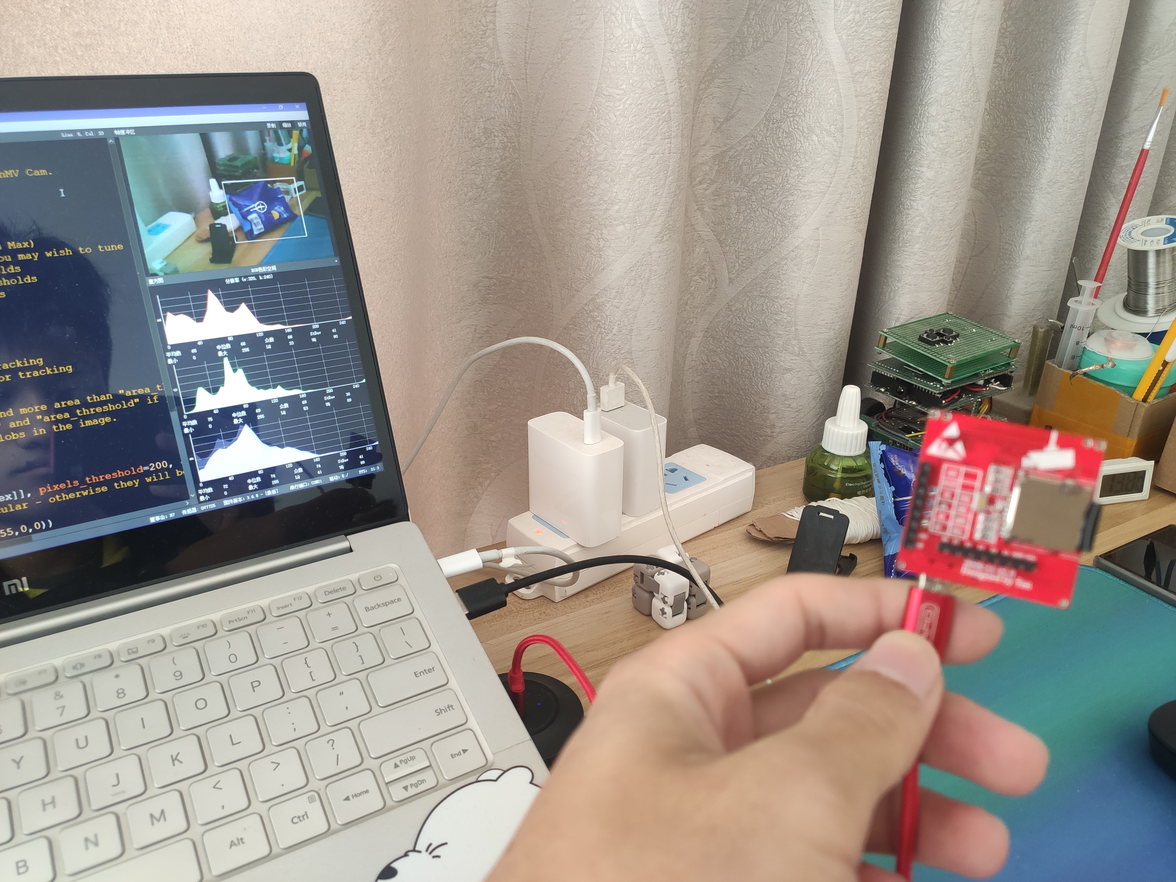
4. Physical display
 |
 |
 |
 |
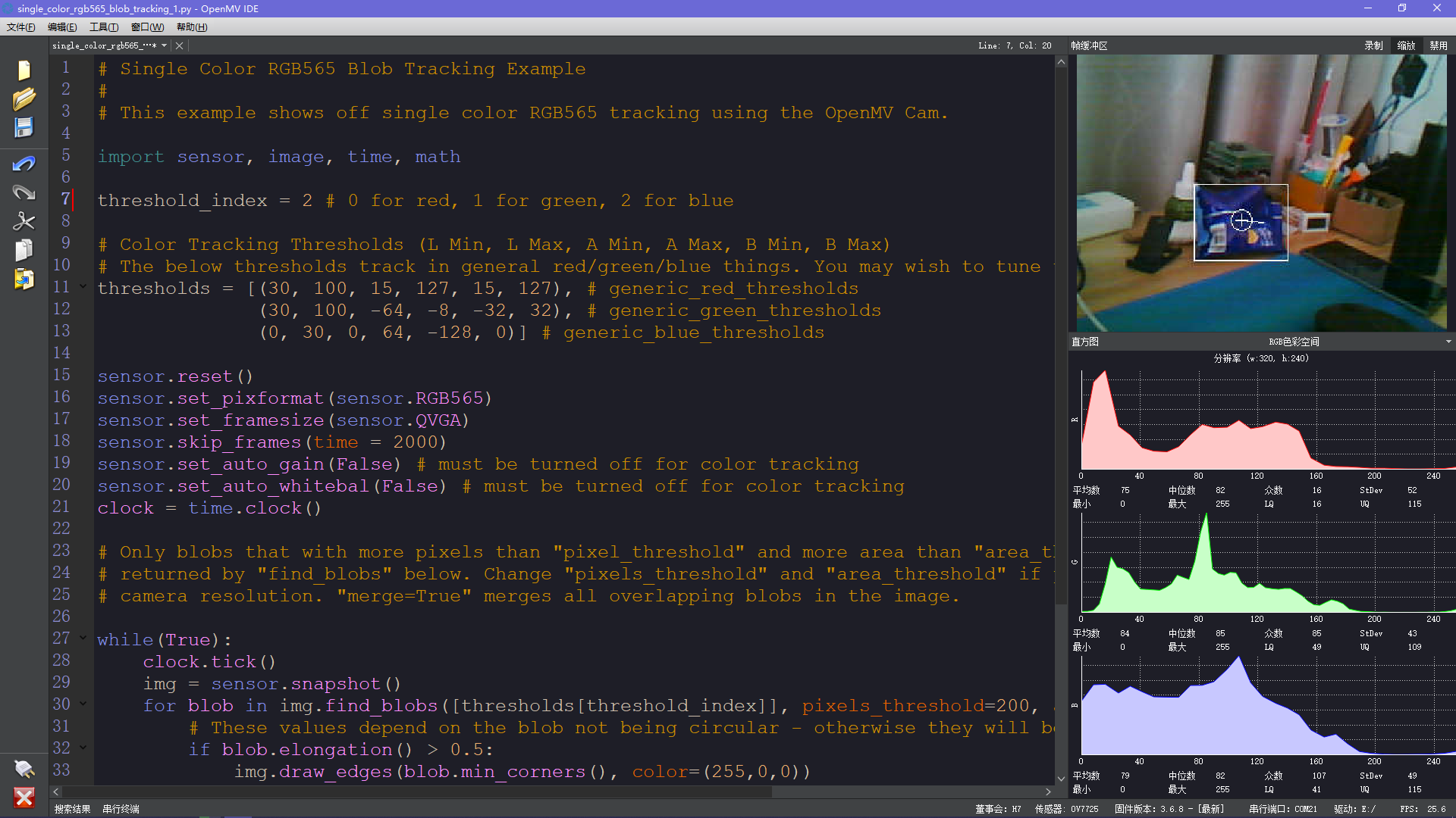
| Identify blue? | |
 |
 |
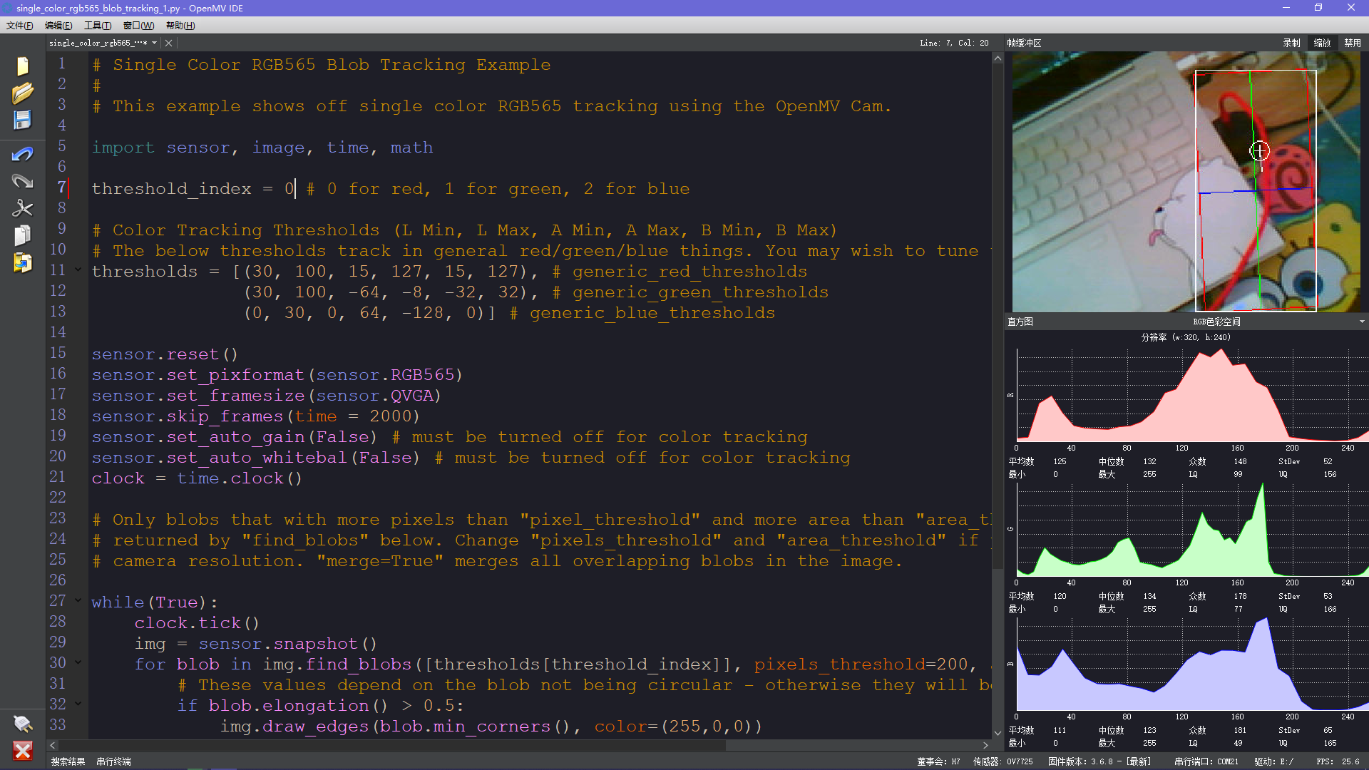
| Identify red? | |
 |
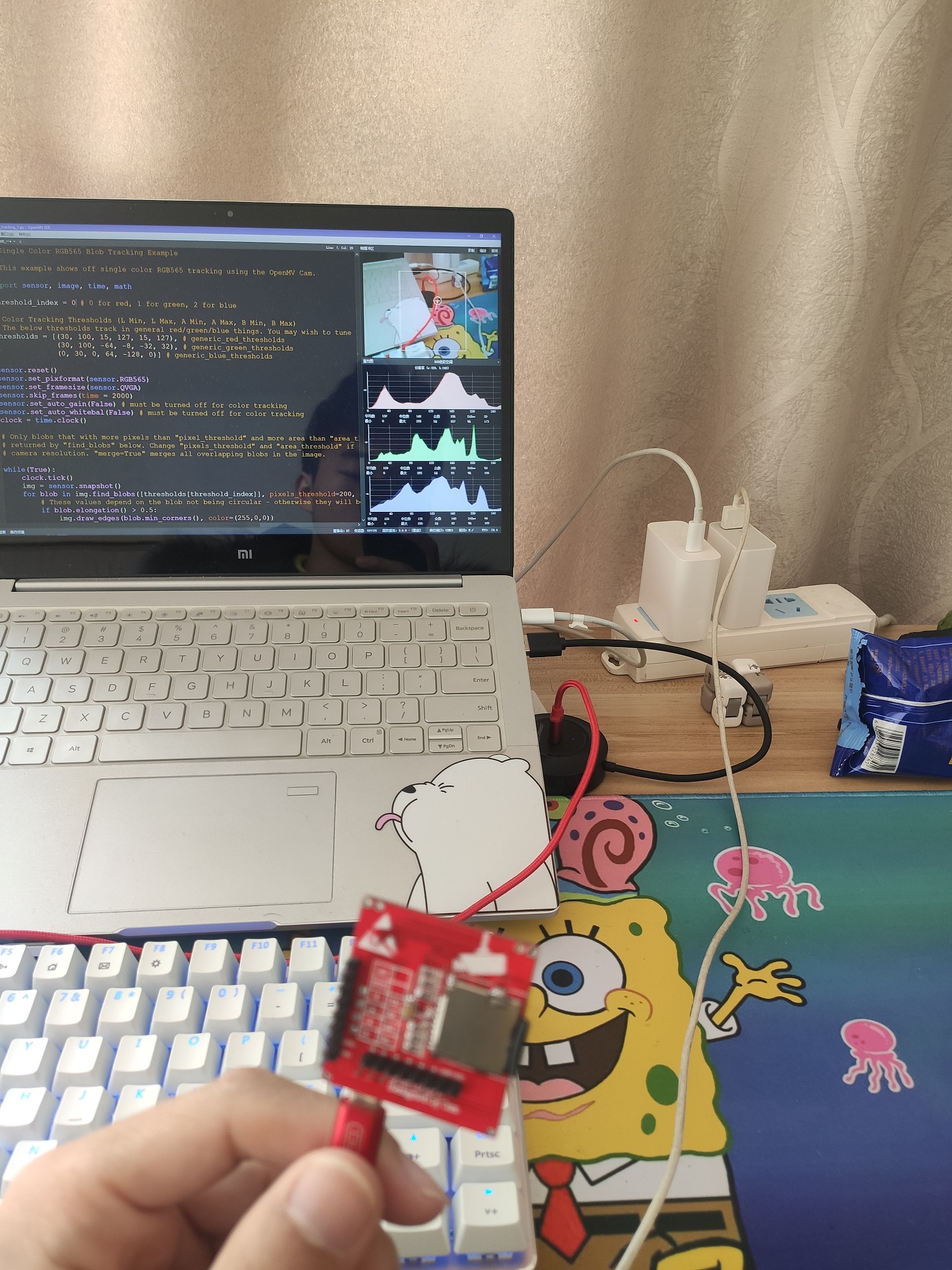 |
The highest is almost 40 frames. It seems that as the color of the screen increases and there are more objects, the number of frames will decrease. The lowest I tried was about 18 frames, usually between 20-30 frames.

All reference designs on this site are sourced from major semiconductor manufacturers or collected online for learning and research. The copyright belongs to the semiconductor manufacturer or the original author. If you believe that the reference design of this site infringes upon your relevant rights and interests, please send us a rights notice. As a neutral platform service provider, we will take measures to delete the relevant content in accordance with relevant laws after receiving the relevant notice from the rights holder. Please send relevant notifications to email: bbs_service@eeworld.com.cn.
It is your responsibility to test the circuit yourself and determine its suitability for you. EEWorld will not be liable for direct, indirect, special, incidental, consequential or punitive damages arising from any cause or anything connected to any reference design used.
Supported by EEWorld Datasheet
EEWorld
subscription
account

EEWorld
service
account

Automotive
development
community

Robot
development
community

About Us Customer Service Contact Information Datasheet Sitemap LatestNews


Room 1530, 15th Floor, Building B,
No.18 Zhongguancun Street,
Haidian District,
Beijing, Postal Code: 100190
China
Telephone: 008610 8235 0740
 京公网安备 11010802033920号

 ETC20HREF


