"Taishan Kao" Electric Toy Audio Modification
: I. Basic Information
"Taishan Kao" is a popular toy among many fans, but unfortunately, it lacks its own background music (BGM). I previously modified it to play Chicken Bro's exclusive BGM during movement. A modification video was posted on Bilibili: Modifying "Taishan Kao"—Giving an Electric Toy its Own BGM.
This modification differs from previous ones, using a circuit board. Inspired by netizens, I added corresponding "Chicken Sounds" for different operating states, totaling four states:
1. Plug in charger—"Wow, it really is you!"
2. Unplug charger or turn off switch—"Isn't your Kun Bro awesome?"
3. Turn on switch—Initiation theme song, and the toy starts moving.
4. Turn on switch while charging—"What are you doing~ Ouch~" (Reminding you not to start while charging)
The above four states are controlled by the RS2255XN analog switch control chip.
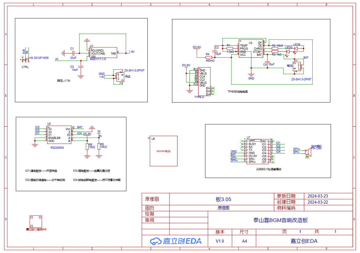
II. The basic schematic diagram
consists of 5 parts: step-down module, charging module, voice control module, battery, and voice playback module.
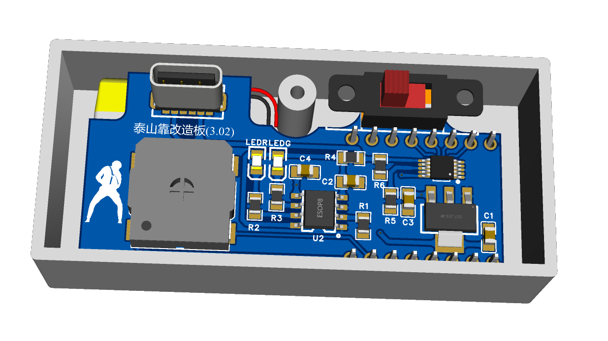
III. PCB Design
The design follows these principles:
1. Utilize existing space and components as much as possible, and minimize destructive modifications;
2. Save money and make soldering easier (use 0805 capacitors, resistors, etc.);
3. Must include GEIGIE elements ;

4. 0.8mm thick FPC board is recommended, as thicker boards will affect installation.
Front and
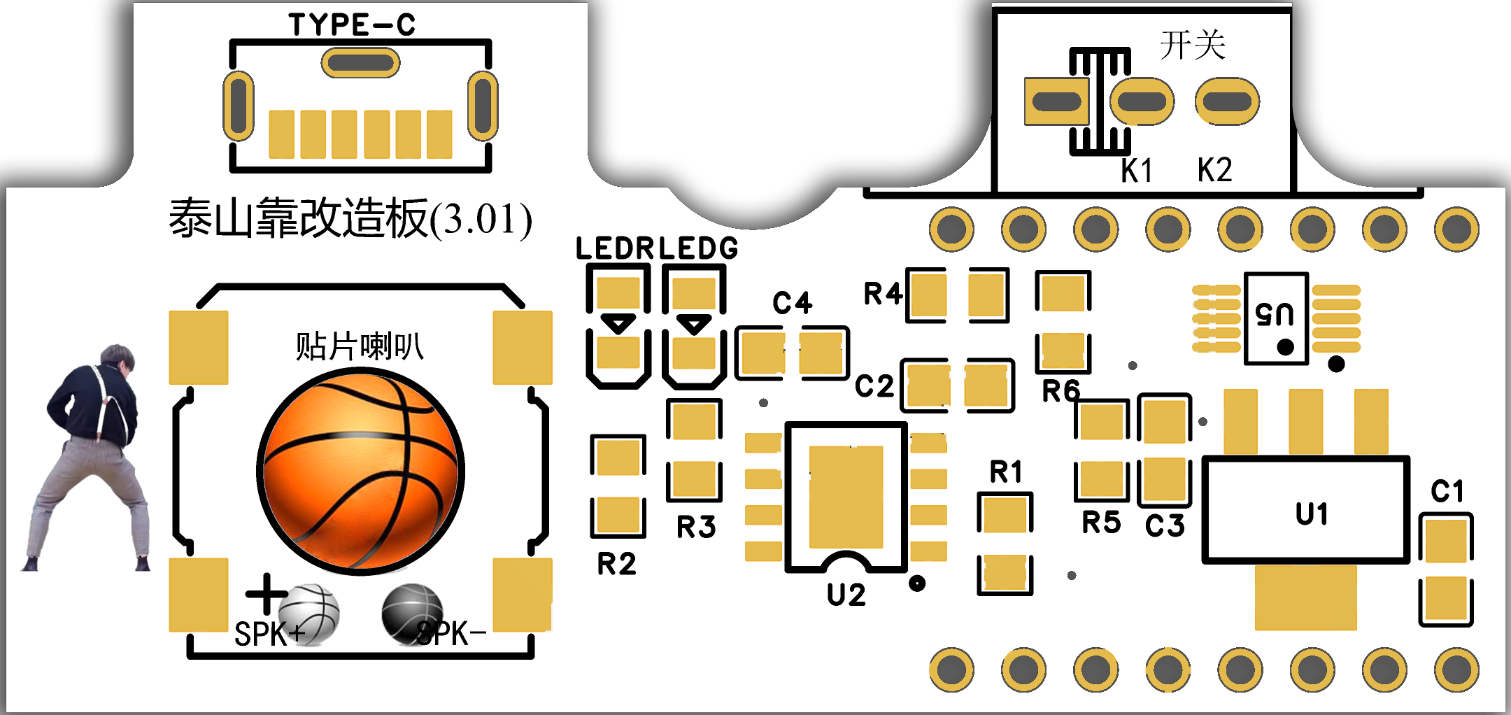
back

IV. Shell Design
Since the Taishan Kao (a type of cardboard box) already has a shell, you need to drill holes in the back cover yourself. Therefore, two options are provided here.
(I) Do it yourself. Drilling holes in the existing back cover requires strong hands-on skills, but the advantage is that it saves money. Here I provide a drilling positioning file, which can be printed out and pasted onto the back cover for easy drilling positioning. See Attachment 1.
(II) 3D printing. If you have plenty of money, or your hands-on skills are too poor, or you have a 3D printing voucher, you can choose 3D printing. You only need to print the back cover.
Note: Because JLCPCB's 3D design software has certain limitations compared to professional CAD software, I re-drew a 3D model of the back cover using UG, see Attachment 2. (You can also use the 3D model in JLCPCB EDA without much problem.)

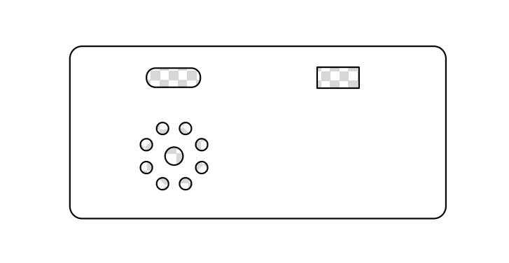
V. Panel Design
Since JLCPCB provided a panel coupon, take advantage of it. Of course, you can also print the corresponding color stickers yourself.

VI. Bill of Materials and Other Notes
1. Most materials can be purchased from the LCPCB online store. For ease of soldering components, I mainly use 0805. Of course, if you want to use 0603 or others, just replace them with the same value, and you will need to modify the schematic diagram yourself.
2. For voice, I directly used the readily available JQ8900-16P voice module, which can be purchased on Taobao. The relevant configuration files are in Attachment 3 (just put the 4 decompressed files in the root directory). Of course, you can also modify the voice later (explore Attachment 4 yourself).
3. The motor and battery terminals are optional; you can solder the corresponding wire ends onto the large solder pads. I designed this to facilitate installation and battery replacement.
4. The slide switch is also optional; it is exactly the same as the original.
5. Ideally, a 702025 battery should be used, as its thickness fits perfectly (however, LCSC is out of stock, so a 502025 battery can be used as a substitute, requiring the bottom of the battery to be raised by 1-2mm).
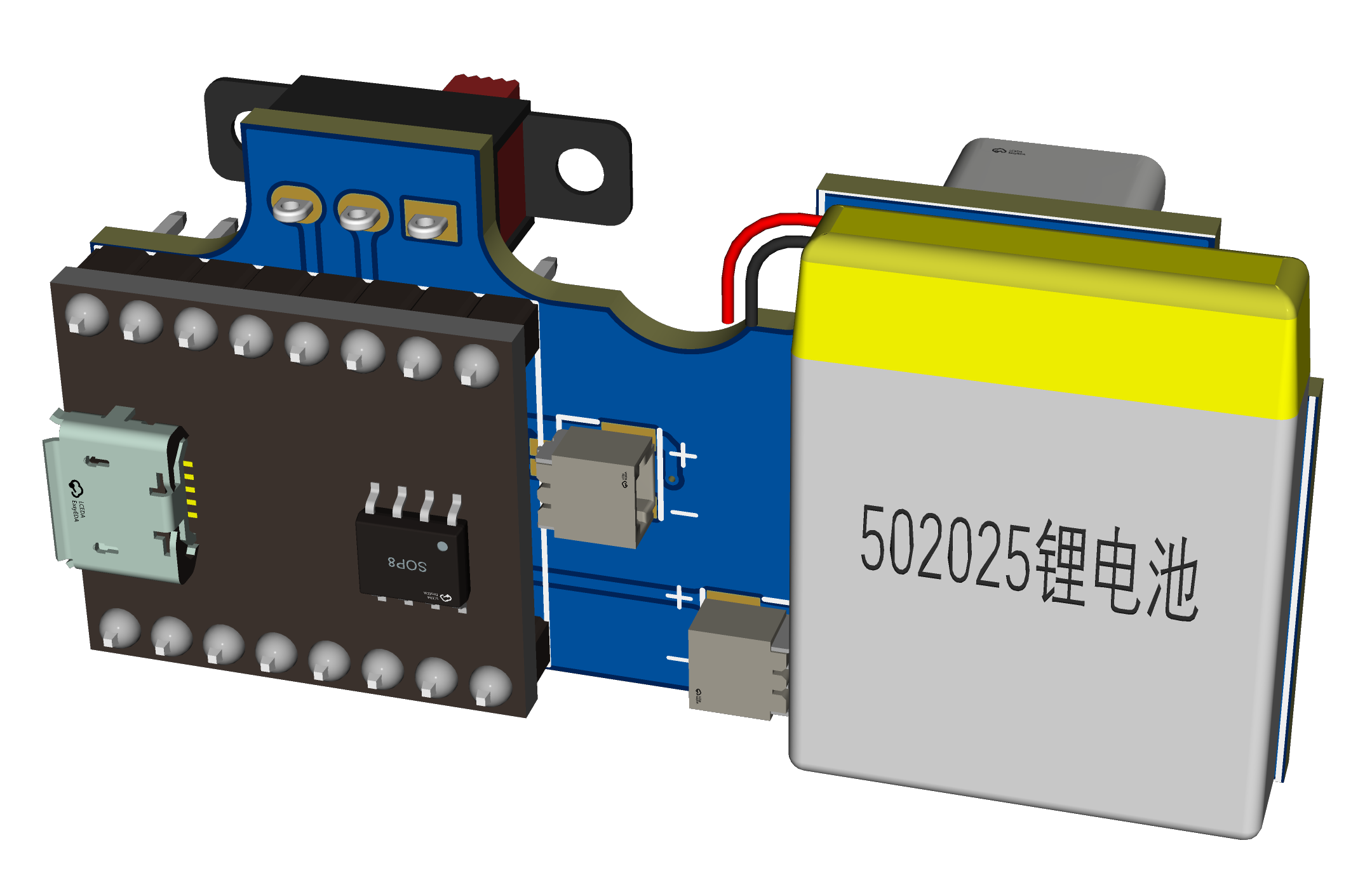
VII. Assembly :
Assemble and solder as shown in the diagram, then install it into the original casing. Don't forget the motor wires; make sure to connect the corresponding wires. The simulation diagram is slightly incomplete.
Assembly is relatively simple. The tutorial has been uploaded to Bilibili: Electronic "Fool's Fun" - Taishan's Toy Speaker Modification Board Soldering and Assembly Tutorial

VIII. Results
: Enough talk, watch the video
. IX. Some Notes:
1. Due to several design changes, it differs slightly from the initial version. Some images haven't been updated yet, so please pay close attention.
2. The charging module references Animal's open-source project | Tp4056 Charging Module (Compatible with Perforated Boards) - LCSC EDA Open Source Hardware Platform (oshwhub.com). Thank you!
3. This design is open-source for learning and exchange; commercial use is prohibited without permission.
4. The finished products will be available on Xianyu (a second-hand marketplace). If you're interested, please visit https://m.tb.cn/h.5CoC7Qa?tk=iiNNWoOzEUH.
5. To expedite the open-source release, I haven't had time to print the back cover and panel yet. I'll add them later if needed.


 京公网安备 11010802033920号

 TC210HT-3R3L-RC


