Parallel Power Supply System for Switching Power Supply Modules
I. Original Question:
Design and build a parallel power supply system consisting of two 8V DC-DC modules, each with a rated output power of 16W (see Figure 1).

1. Basic Requirements
(1) Adjust the load resistance to the rated output power operating state, and the DC output voltage of the power supply system UO = 8.0 ± 0.4V.
(2) Under the rated output power operating state, the efficiency of the power supply system is not less than 60%.
(3) Adjust the load resistance to maintain the output voltage UO = 8.0 ± 0.4V, so that the sum of the output currents of the two modules is IO = 1.0A and the current is automatically distributed according to the I1:I2 = 1:1 mode, and the absolute value of the relative error of the output current of each module is not greater than 5%.
(4) Adjust the load resistance to maintain the output voltage UO = 8.0 ± 0.4V, so that the sum of the output currents of the two modules is IO = 1.5A and the current is automatically distributed according to the I1:I2 = 1:2 mode, and the absolute value of the relative error of the output current of each module is not greater than 5%.
2. Performance
(1) Adjust the load resistance to maintain the output voltage UO=8.0±0.4V, so that when the load current IO varies between 1.5~3.5A, the output current of the two modules can be automatically distributed in the range of (0.5~2.0) according to the specified ratio, and the absolute value of the relative error of the output current of each module is not greater than 2%.
(2) Adjust the load resistance to maintain the output voltage UO=8.0±0.4V, so that the sum of the output currents of the two modules IO=4.0A and the current is automatically distributed in the mode of I1:I2=1:1, and the absolute value of the relative error of the output current of each module is not greater than 2%.
(3) Under the rated output power working condition, further improve the efficiency of the power supply system.
(4) Have load short circuit protection and automatic recovery function, and the protection threshold current is 4.5A (a deviation of ±0.2A is allowed during debugging).
(5) Others.
II. Simulation Verification:
① Design Specifications for a Single Buck Power Converter Module:
Based on the problem, the specifications for the Buck power converter can be defined as follows:
Input voltage: 24V
, Output voltage: 8V, Maximum output current: 2A, Switching
frequency: 100kHz
, Ripple voltage: 50mV, Inductor ripple current coefficient: 0.1.
Requirement: Within 1µs, when the output current changes from 200mA to 2A, the voltage change should not exceed 100mV.
To facilitate subsequent formula derivation, the above specifications are replaced with symbols, such as:
Input voltage: Vin, Output
voltage: Vout, Output current: Iout, Switching frequency: fs,
Inductor ripple current coefficient: δ, Ripple voltage: ΔV. That is:

② Derive the required power device values from the Buck power converter module specifications:
From the properties of the Buck power converter, we know:

(D is the duty cycle of the Buck circuit)
From the properties of the ripple voltage, we can determine the angular frequency of the LC filter related to the Buck circuit and the value of the inductor:


(f0 is the angular frequency of the LC filter related to the Buck circuit, L is the inductance value)
Therefore, the value of the capacitor in the LC filter can be obtained:

By deriving the above formula and combining it with the nominal value of E24, we can finally determine the parameters of the LC filter in the Buck circuit, then:
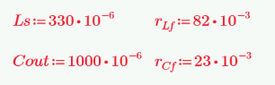
(Ls is the selected inductor, rLf is the equivalent series resistance of the inductor)
(Cout is the selected capacitor, rCf is the equivalent series resistance of the capacitor)
③ Simulate a single Buck power converter module:
A single Buck power converter module can be simulated using the above devices. With the help of PSIM, we have:

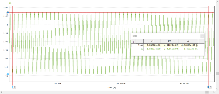
Its time-domain output characteristics are:

where the output voltage ripple is: 3.34mV

and the inductor ripple current is: 145mA
④ Design of a closed-loop control circuit for a single Buck power converter module:
To facilitate the subsequent design of the control loop using a microcontroller, a single Buck power converter module is controlled in voltage mode and operates in continuous current mode (CCM). Therefore, a small-signal model of the Buck power converter is established, and its transfer function is:

Using MATLAB, the Bode plot and root locus plot of the transfer function of a single Buck power converter module can be obtained, showing:

From the figure, it can be seen that the system consists of one zero and a pair of conjugate poles, and the values of the zero and conjugate poles on the real axis are:

Therefore, for this system, a Type III compensator is chosen for compensation, and its transfer function expression is:
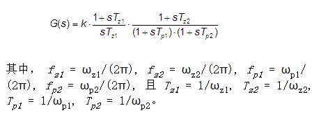
Then, for this system, the manual zero-pole placement method is used for system control design, as shown below:
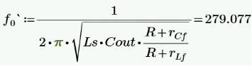
To eliminate the peak value of the LC filter, a double zero is placed at its resonant frequency f0 (279Hz).
The first pole is placed at the highest zero (8kHz) to force a decrease in gain.
The second pole is placed at half the switching frequency (50kHz) to avoid noise interference.
Therefore:

Using MATLAB to build the closed-loop control block diagram of the system,

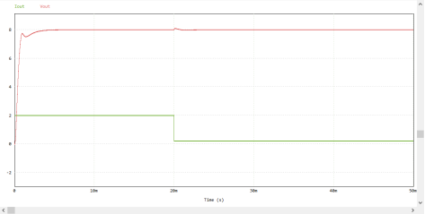
its time-domain characteristics are:

Using PSIM to build the closed-loop control circuit of a single Buck power converter module,

its time-domain characteristics are:

where the output voltage ripple is: 3.41mV.

Introducing the load module makes the output current change from 200mA to 2A within 1us, and its time-domain characteristics are:
and when the output current changes, its overcharge is: 99.7mV,

which meets the previously set Buck power converter specifications. Thus, in summary, the design of a single Buck power converter is complete.
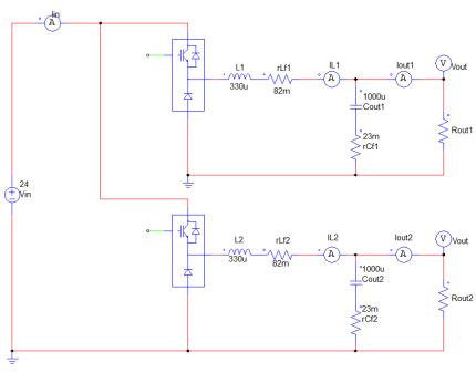
⑤ Analysis and modeling of the parallel power supply system of switching power supply modules:
From the problem, the circuit of the parallel power supply system of switching power supply modules can be built:
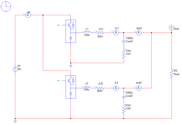
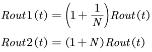
where (Iout1 is the output current of module 1, Iout2 is the output current of module 2, Iout is the total output current, and N is the ratio between Iout1 and Iout2):
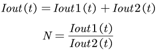
From the above formula, we can solve for:
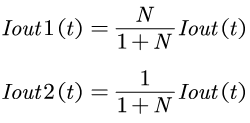
And because:

Therefore, the output resistances of module 1 and module 2 are respectively:
Therefore, the circuit can be transformed into:
Therefore, the analysis of the parallel power supply system of switching power supply modules returns to the analysis of a single module.
⑥ Select the control strategy for the parallel power supply system of switching power supply modules:
There are a variety of control methods for the parallel power supply system of switching power supply modules, among which the representative ones are: average current method and master-slave current method.
(1) Average current method: refers to connecting all modules to each other through a current sharing bus, and each sub-module obtains its own current reference signal from the bus, and controls the current of each module through the adjustment of the control loop.
(2) Master-Slave Current Method: The master-slave current method designates one module as the master module, and its output current is used as the current command signal; the remaining modules are slave modules, and their output current follows the current of the master module to achieve current sharing.
Comparing the average current method and the master-slave current method, the average current method can show better time-domain characteristics when the ratio of the output currents of the two modules is 1. However, when the ratio of the output currents of the two modules is not 1, the output voltage shows a large deviation. According to the requirements of the problem, the output voltage of the parallel power supply system of switching power supply modules needs to be maintained at 8V. In contrast, the master-slave current method can control the voltage of one module and track the current of the other module. Therefore, it can be said that the master-slave current method is better than the average current method under this problem. So, for the control strategy of the parallel power supply system of switching power supply modules, we choose the master-slave current method.
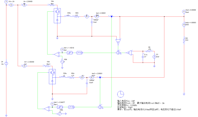
⑦ Design the master-slave current method control strategy:
Use MATLAB to build the closed-loop control block diagram of the system, that is:

From ⑤ we can understand that the analysis of the parallel power supply system of the switching power supply module can be performed on a single module. Therefore, the design of the compensator of the system returns to the content of ②~④. Thus, by the same logic, we can obtain:
This concludes the simulation verification part of this problem.
III. Physical verification section:
(1) Hardware design section:
① Main power circuit section: Buck power converter topology
② MOS drive circuit section: Half-bridge controller (IR2104)
③ Sampling circuit section: Output voltage sampling, output current sampling
④ Controller circuit section: STC32G (required ports: Module 1 output voltage and current, Module 2 output voltage and current, two PWM signals, in addition to power supply ports VCC and GND, i.e., a total of 4 ADCs, two PWM signals and power supply VCC and GND are required)
⑤ Protection circuit section: Soft start circuit, short circuit protection circuit, self-recovery circuit (after analysis, it was selected to be implemented through software)
⑥ Auxiliary circuit section: Auxiliary power supply (powers the driver, current sampling module and controller, i.e. 12V and 5V)
(2) Hardware block diagram:
Hardware design block diagram of the parallel power supply system of switching power supply modules:

(3) Software design section:
① Main control software section design:
The parameters of the Type III compensator in the analog domain have been designed in the simulation verification. In the software design section, the compensator in the analog domain is mainly discretized into the difference equation required by digital control. There are three main methods for discretizing analog compensators: the impulse response invariance method, the step response invariance method, and the bilinear transform method. In this software design section, for simplicity, the impulse response invariance method is chosen to obtain the digital compensator required for this control system.
Regarding the impulse response invariance method, we take an integral controller. Let the output of the integral controller be Vout(t) and the input be Vin(t). Then the transfer function of the integral controller is:
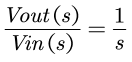
Its time domain expression is:

Discretize the expression in the time domain and use the rectangular method for numerical integration, that is, replace integration with summation. We obtain the output of the controller at the (n-1)th and nth sampling times as:
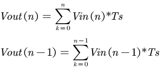
(where Ts is the sampling period)
By observing the above formula, we can write the formula as:

Performing the Z-transform on the above formula, we have:

Equivalent to the analog transfer function and the discrete transfer function, we have:
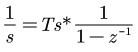
Simplify to:

(where fs is the sampling frequency)
Therefore, for the discretization design of the Type III compensator, we can substitute the above formula, and we have:
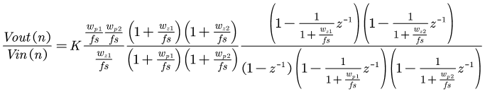
Simplify to:

Taking the sampling frequency as 2000Hz, combined with the simulation verification results, we have:
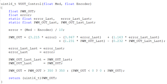
The control design of another module can be obtained in the same way. Thus, the software design part is completed.
② Protection Circuit Section (Supporting the circuit, but implemented in software due to cost considerations):
1. Soft-start Circuit:
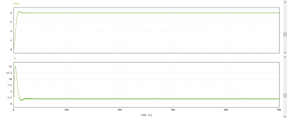
The essence of a soft-start circuit is to prevent sudden current flow during startup. It slows down the rise of the output voltage by minimizing overcurrent during startup. For linear feedback systems, soft-start addresses the issue of mitigating the maximum difference between the reference signal and the feedback signal during startup. This can be discussed as follows:

Simulation shows that during startup, the inductor current reaches 15A at the instant of power-on due to the maximum difference between the reference signal and the feedback signal, posing a serious challenge to the lifespan of the circuit components.
To implement soft-start for a linear feedback system, the feedback signal and the reference signal can be processed separately. For the feedback signal, the solution is simple: reduce the loop's response speed. However, for this system, a fast-responding system is needed. Therefore, for soft-start of this system, only the reference signal needs to be considered.
For a fixed reference signal, its time-domain manifestation during startup is a step signal, which causes sudden current flow in the circuit during startup. To address this, it's easy to think of using a first-order hysteresis system to minimize the signal's startup. Its transfer function is expressed as:
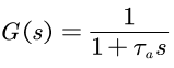
Then:

In the time domain, it is expressed as:

(At this point, the peak current of the inductor in the Buck power converter is 2.4A, which is perfect).
Discretizing the first-order hysteresis system into the difference equations required for digital control (using the impulse response invariance method), we have:
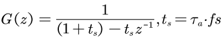
Taking the sampling frequency as 2000Hz, and combining the simulation results, we have:
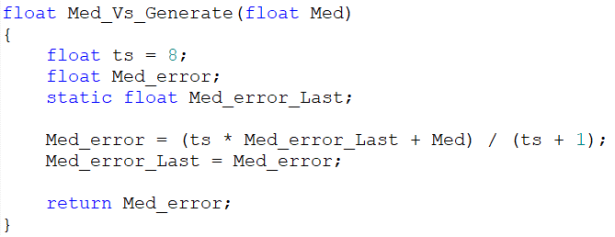
Thus, the soft-start design is complete.
2. Short-circuit protection circuit:
Compared to soft-start protection, short-circuit protection software implementation is relatively simple. It only requires adding and comparing the sampled currents of the two modules, as shown below:
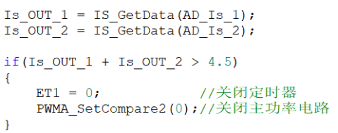
Thus, the short-circuit protection design is complete.
(5) Physical verification section:
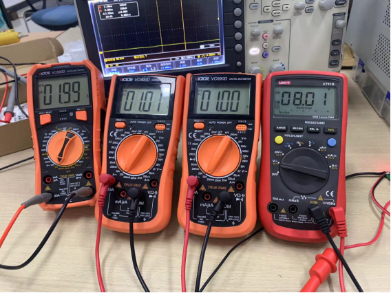
For basic requirement (2) (the efficiency of the power supply system is not less than 60% under the rated output power working state), the input voltage is 24V and the input current is 0.738A;

the output voltage is 8.01V and the output current is 1.99A;

the efficiency is 89.995%;

For basic requirement (3) (adjust the load resistance to keep the output voltage UO=8.0±0.4V, so that the sum of the output currents of the two modules is IO=1.0A and the current is automatically distributed according to the I1:I2=1:1 mode, and the absolute value of the relative error of the output current of each module is not greater than 5%), we have:
where the relative error of Iout1 is 1% and the relative error of Iout2 is 0%.
For the basic requirement (4) (adjust the load resistance to maintain the output voltage UO = 8.0 ± 0.4V, so that the sum of the output currents of the two modules is IO = 1.5A and the current is automatically distributed in the I1:I2 = 1:2 mode, and the absolute value of the relative error of the output current of each module is not greater than 5%), we have:
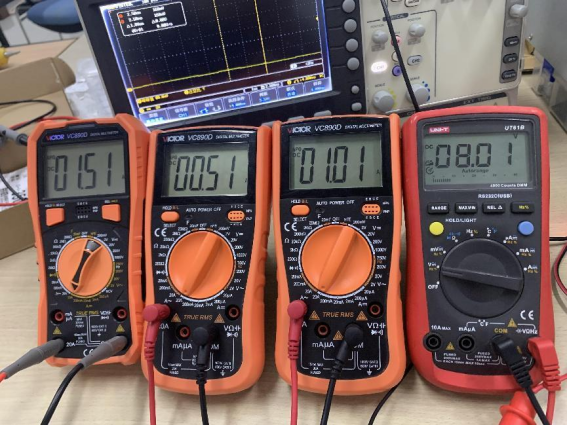
where the relative error of Iout1 is 2% and the relative error of Iout2 is 1%.
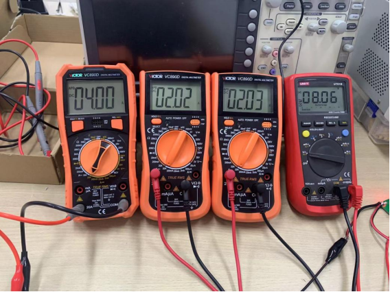
For the performance requirement (1) (adjust the load resistance to maintain the output voltage UO = 8.0 ± 0.4V, so that when the load current IO varies between 1.5 and 3.5A, the output currents of the two modules can be automatically distributed in the range of (0.5 to 2.0) according to the specified ratio, and the absolute value of the relative error of the output current of each module is not greater than 2%), we have:
When the load current is 3A and the ratio of the output currents of the two modules is 0.5, we have:
where the relative error of Iout1 is 0.5% and the relative error of Iout2 is 0%.
When the load current is 3.03A and the ratio of the output currents of the two modules is 0.5, we have:

where the relative error of Iout1 is 0% and the relative error of Iout2 is 1.49%.
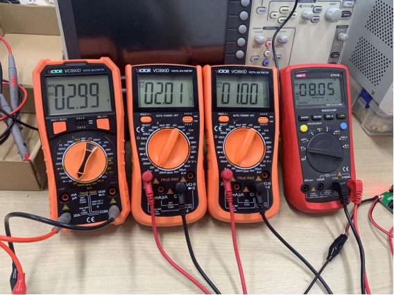
For (2) adjusting the load resistance to keep the output voltage UO=8.0±0.4V, so that the sum of the output currents of the two modules IO=4.0A and the current is automatically distributed in the I1:I2=1:1 mode, and the absolute value of the relative error of the output current of each module is not greater than 2%, we have:
where the relative error of Iout1 is 1% and the relative error of Iout2 is 1.5%.
At this point, the physical verification part is completed.


There are some pin configuration problems, and
it is strongly discouraged to replicate them!
It is strongly discouraged to replicate them!
It is strongly discouraged to replicate them!
It is strongly discouraged to replicate them! !!!
Absolutely NOT recommended to re-release this item!!! !!!
Absolutely NOT recommended to re-release this item!!! !!!
Absolutely NOT recommended to re-release this item!!! !!!
Absolutely NOT recommended to re-release this item!!!


 京公网安备 11010802033920号

 DL-5320S-C270-HTS


