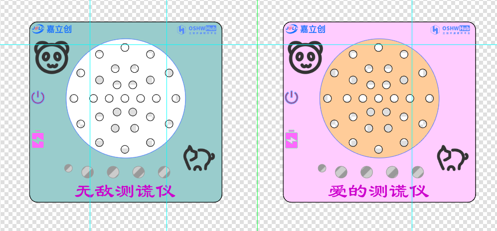
Product Description:
This product originated
from training children to be honest from a young age. A lie detector was specifically designed, but it doesn't actually detect lies.
It's meant to teach children that this device can detect whether they are lying.
It also allows children to interact better, testing each other's lies.
Couples can also use it. However,
there are techniques involved; the other person must be convinced that the product can genuinely detect lies.
Product Functions:
1- Wireless control with voice output, e.g., command 8: Don't lie, 9: You're so honest!
2- WS2812 indicates whether someone is lying; red indicates lying, green indicates honesty.
3- WS2812 can be used as a night light.
4- Powered by a 200mAh lithium battery, Type-C charging
. 5- Battery monitoring via Bluetooth.
6- Can also be used as a music player.
Bluetooth available commands.

Product Design
: Hardware Design:
Power Supply:
1- Charging via Type-C.
2- Charging and boosting to 5V via TP5400. The boosting is necessary because the WS2812 requires a power supply above 3.6V.
3-LD0 uses an AMS1117 to 3.3V converter because the MCU power supply cannot exceed 3.6V.
4-USB insertion detection: When PB12 is high, there is input, and Bluetooth will receive a charging notification.
5-Lithium battery is directly connected via a 2.54mm header.
6-Switch controls whether the lithium battery is powered.
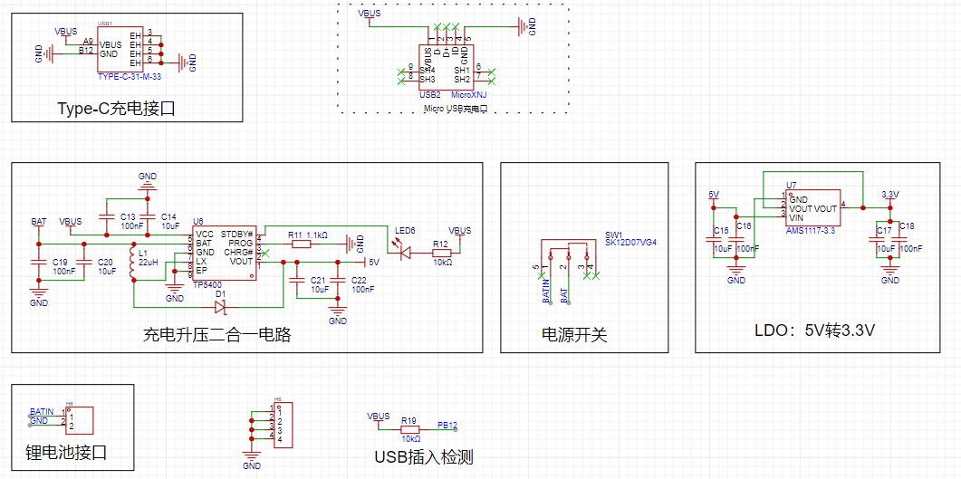
Lithium battery specifications are as follows:

The Bluetooth section
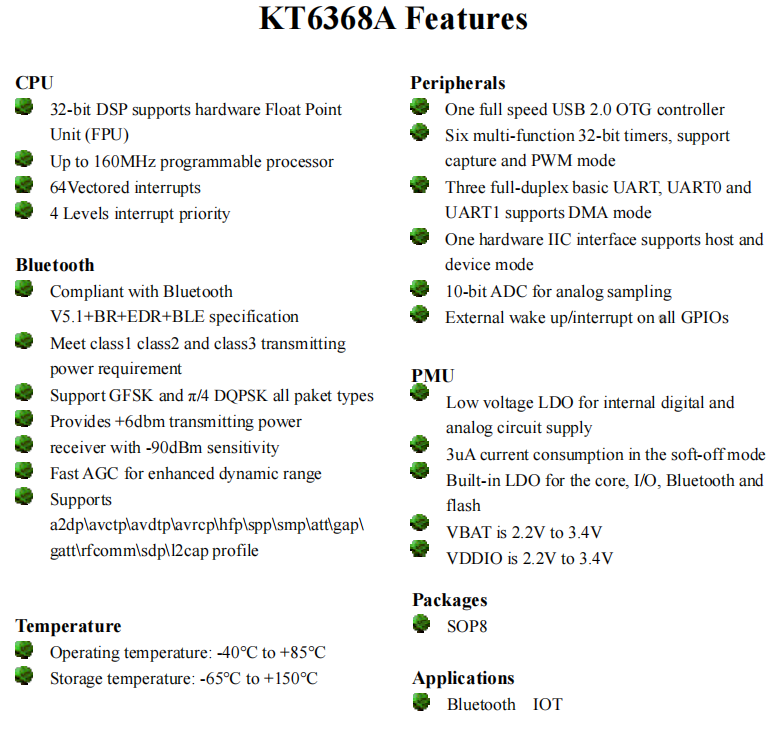
uses a KT6368A chip, which supports dual-mode. Specific specifications are as follows. To reduce power consumption, it is recommended to use the KT6328A, but it only supports BLE.
PB10 is used to quickly determine if Bluetooth is connected.
The principle design is as follows:

KT6368A specifications are as follows:
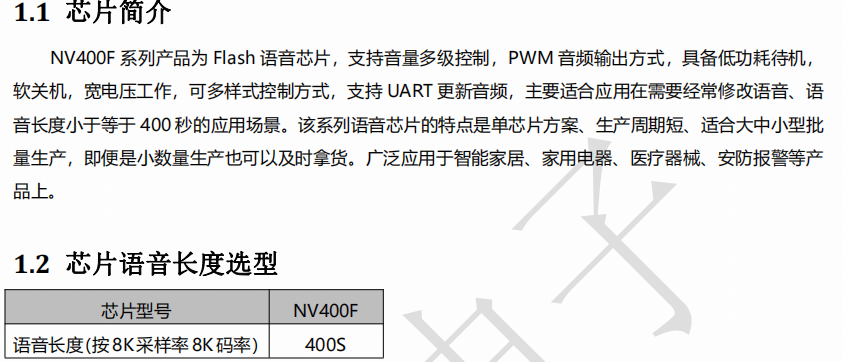
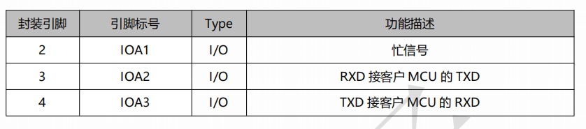
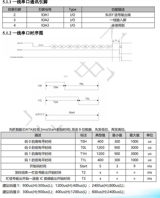
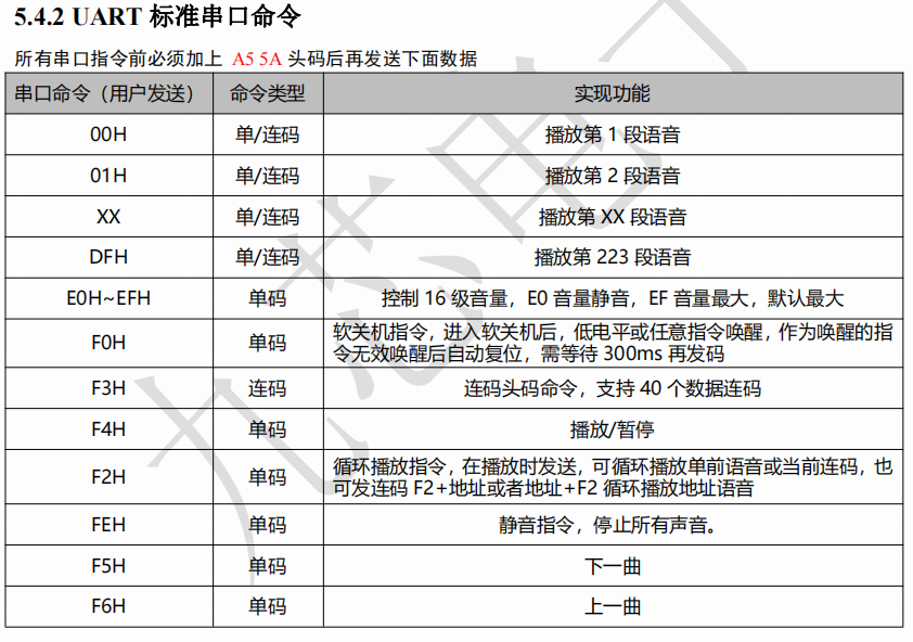
The voice section
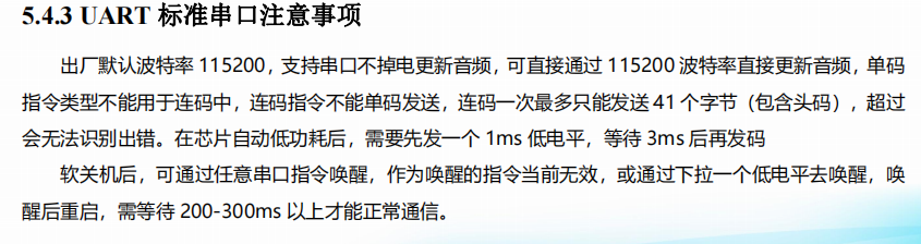
uses an NV400F offline voice chip. It uses a standard serial port for control, with a default baud rate of 115200.
The principle design is as follows:

The core content of this chip is as follows:

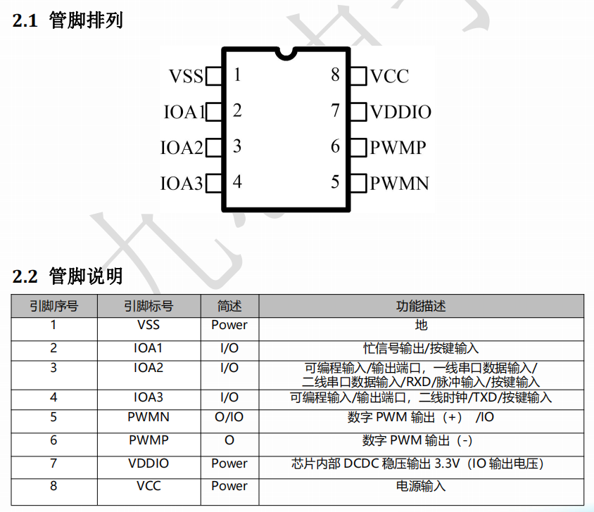
It uses a standard serial port control mode:


Note the BUSY signal; idle is low.
The LED display section
design is as follows:

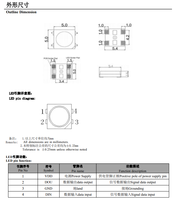
It uses four WS2812B chips. Color control is achieved through the PA7 pin, using SPI+DMA. PA7 is a MOSI pin and can be configured for SPI in transmit-only mode, saving pins.
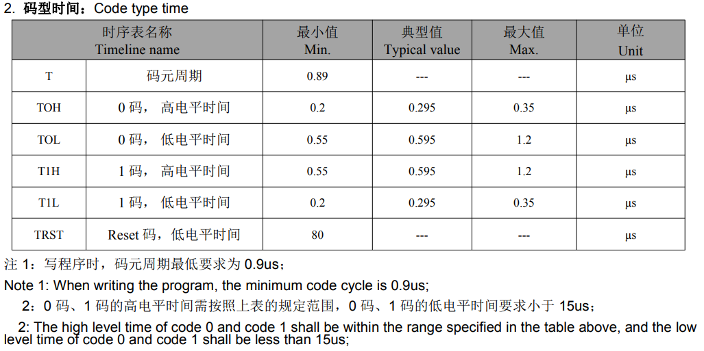
The WS2812 chip uses single-wire communication and transmits signals using return-to-zero (RZ) coding. After power-on reset, the chip receives data from DIN. Once it has received 24 bits of data, the DOUT pin begins forwarding the data, providing input data for the next chip. Before forwarding, the DOUT pin is kept low, during which time the chip does not accept new data. The chip's three PWM output ports (OUTR, OUTG, and OUTB) emit signals with different duty cycles based on the received 24 bits of data, with a period of 4ms. If the input signal at the DIN terminal is a RESET signal, the chip will send the received data to the display. After the signal ends, the chip will start receiving new data again. After receiving the initial 24 bits of data, the chip will forward the data through the DOUT port. Before receiving a RESET signal, the original outputs of OUTR, OUTG, and OUTB remain unchanged. When a low-level RESET code of more than 80us is received, the chip will receive 24-bit PWM data pulse width and output it to OUTR, OUTG, and OUTB.
Power input voltage: 3.5-7.5V
OUT R/G/B constant current value: 12mA
Top SMD Internally integrated high-quality external control single-wire serial cascade constant current IC
control circuit is integrated with the chip in SMD 5050 components to form a complete external control pixel point, with uniform and consistent color temperature effect. Built
-in data shaping circuit, after any pixel point receives a signal, it is shaped before output, ensuring that the waveform distortion is not added.
The default power-on light is not lit.
Gray scale adjustment circuit (256 levels of gray scale adjustable)
Data shaping: After receiving the data of this unit, the subsequent data is automatically shaped and output.
Built-in high-precision and high-stability oscillator
single-wire data transmission, which can be infinitely cascaded.
High data protocol compatibility.
Data transmission rate: 800Kbps.


Note the following settings:

The main control part
is designed as follows:

The MCU uses STM32F103C6T6, but F030 is actually more power-efficient and lower cost.
The main control chip has the following functions:
1- Control the voice chip;
2- Control the Bluetooth chip;
3- Monitor the lithium battery level;
4- Detect USB insertion status;
5- Monitor Bluetooth connection status;
6- Control the WS2812 LED.
Its resources are as follows:
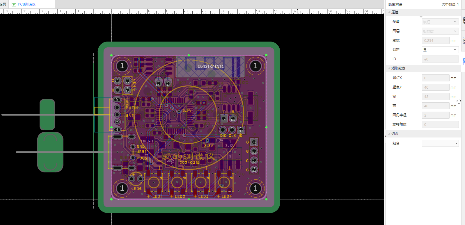
PCB design
uses LCSC EDA .
Double-sided board, 1.6mm, FR-4 board material.
43X40mm.
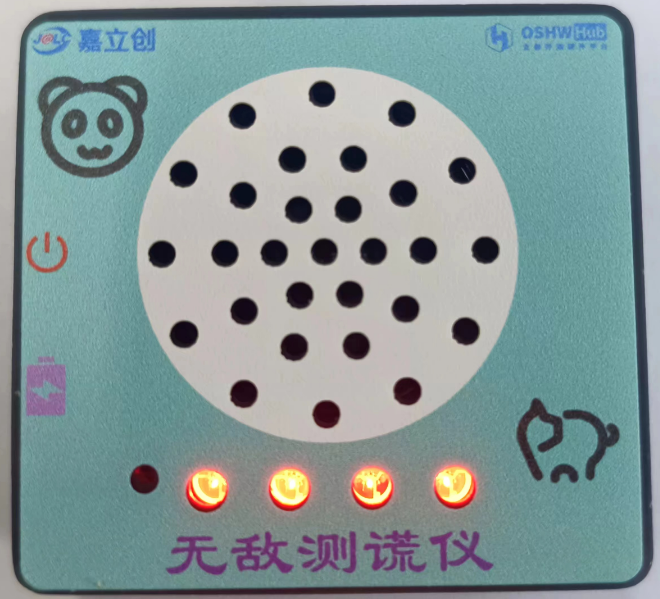
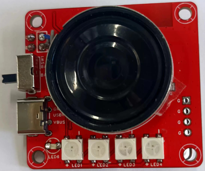
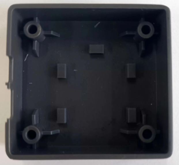
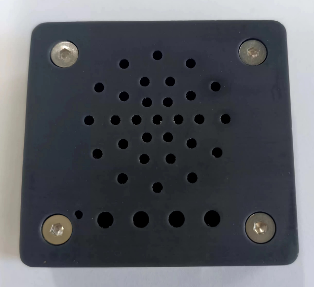
Actual sample is shown below:

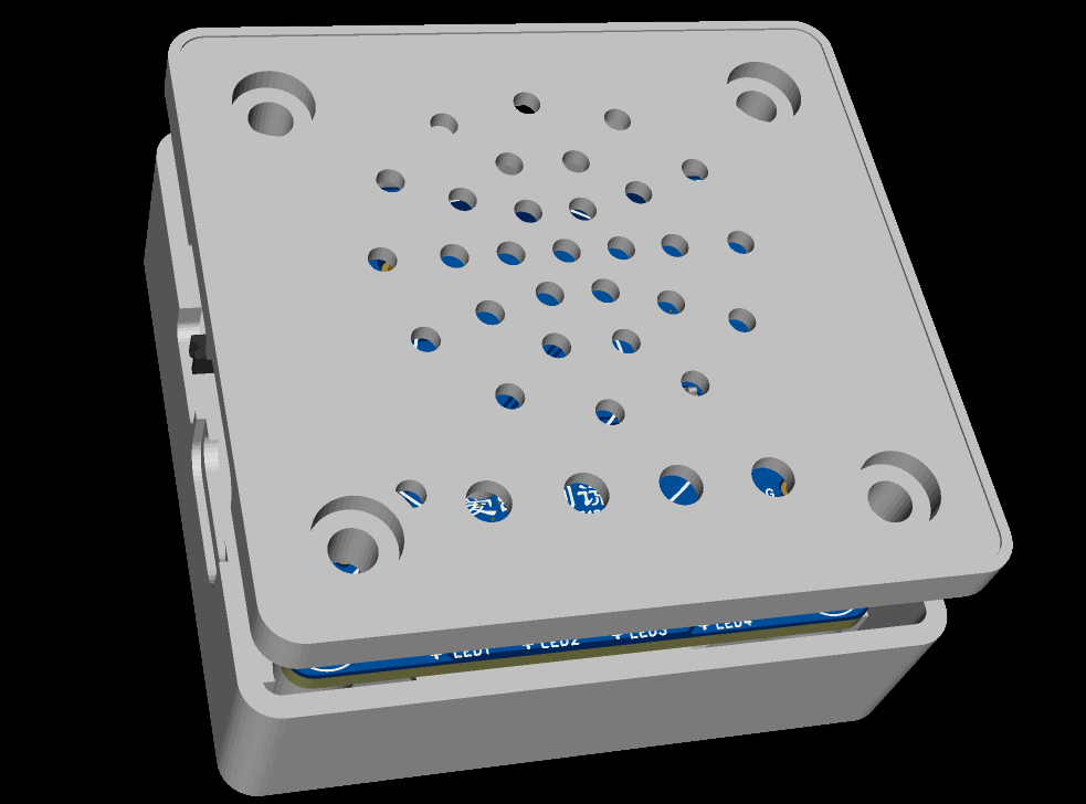
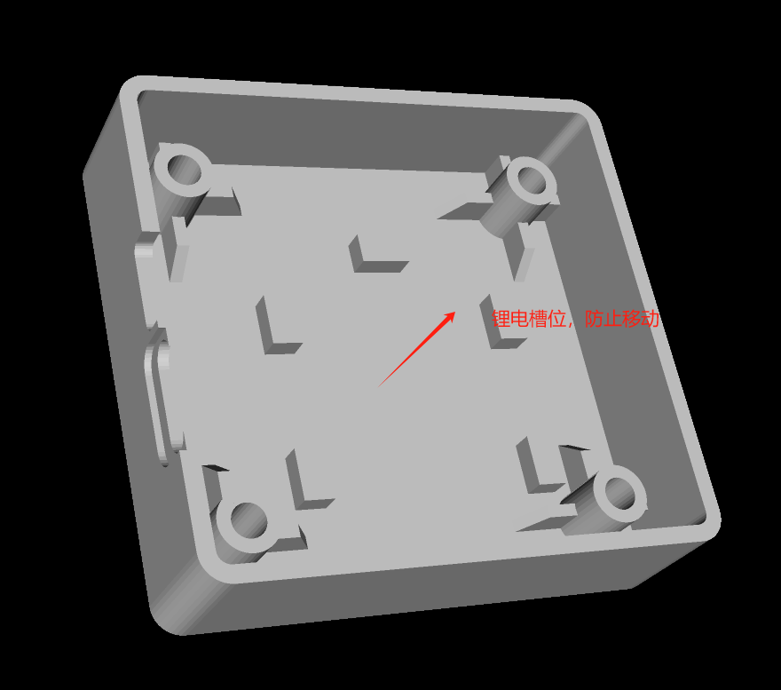
3D shell design uses LCSC EDA. Overall design : Bottom shell physical image ; Top cover: Physical image supplement. It is recommended to use a different color for printing. I chose the cheapest one, so the color is random; black doesn't look good. Shell panel design uses LCSC EDA. Actual effect is shown below: Software design and development tools and environment use a combination of CubeMX and Keil5, developed using C language. Design concept: 1- Battery sampling, data acquisition through ADC1. 2- Detect Bluetooth connection; if connected, output battery level to the display and receive commands. 3- Control the voice chip to output voice. 4- Enter low power mode. Detailed information about the Bluetooth chip was previously available in the Liangshanpai module development. It will not be discussed further here. Please see the attachment for the code .


Due to video size limitations, please view the product demonstration at the following link:
https://www.bilibili.com/video/BV1tA4m1A7Fb/?vd_source=e36622a05269c0356d6cd566056a2488


 京公网安备 11010802033920号

 SN74HC4020DT


