[Updated 2024.01.03] A 3D design file for the outer shell has been added.
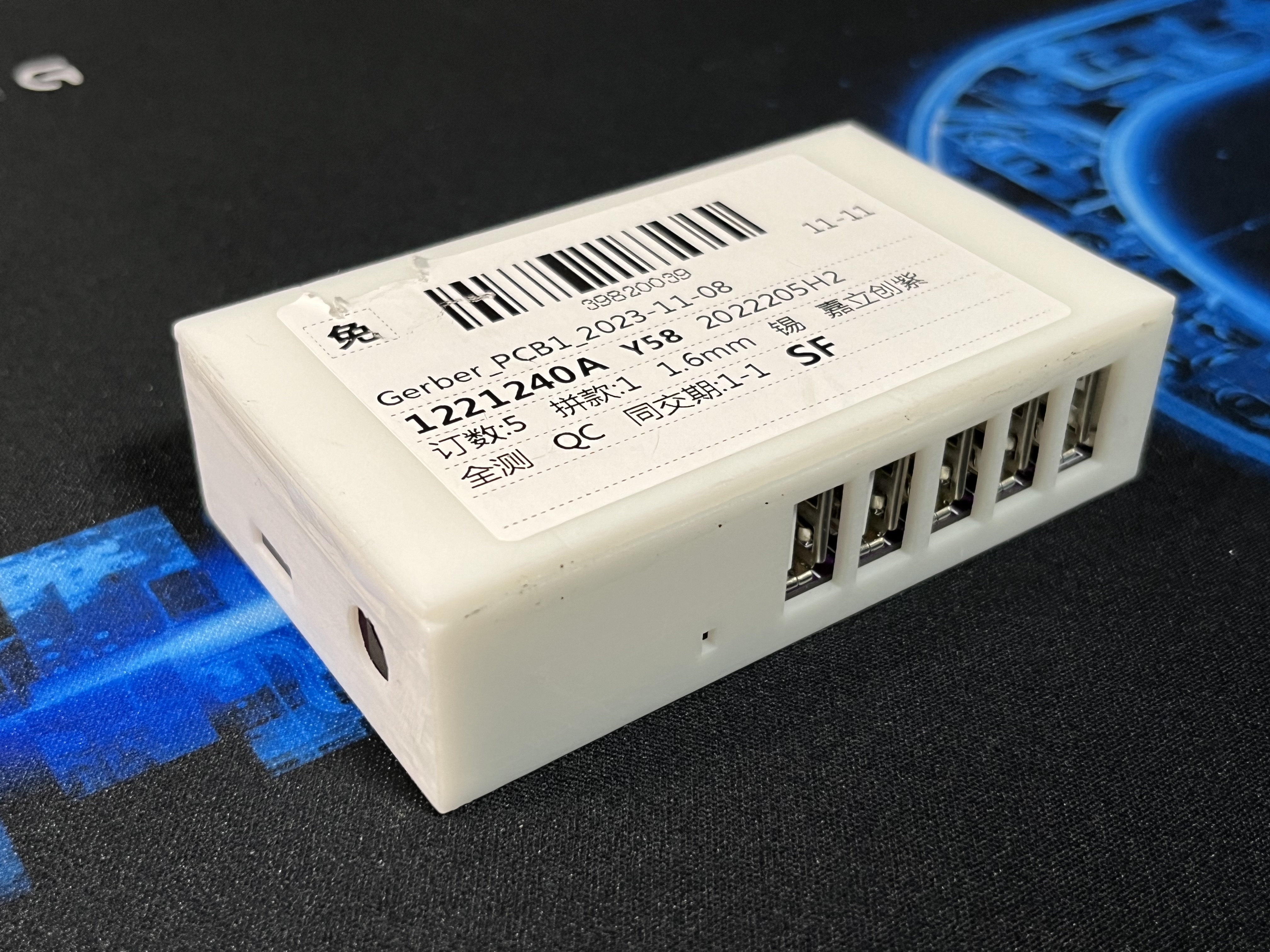
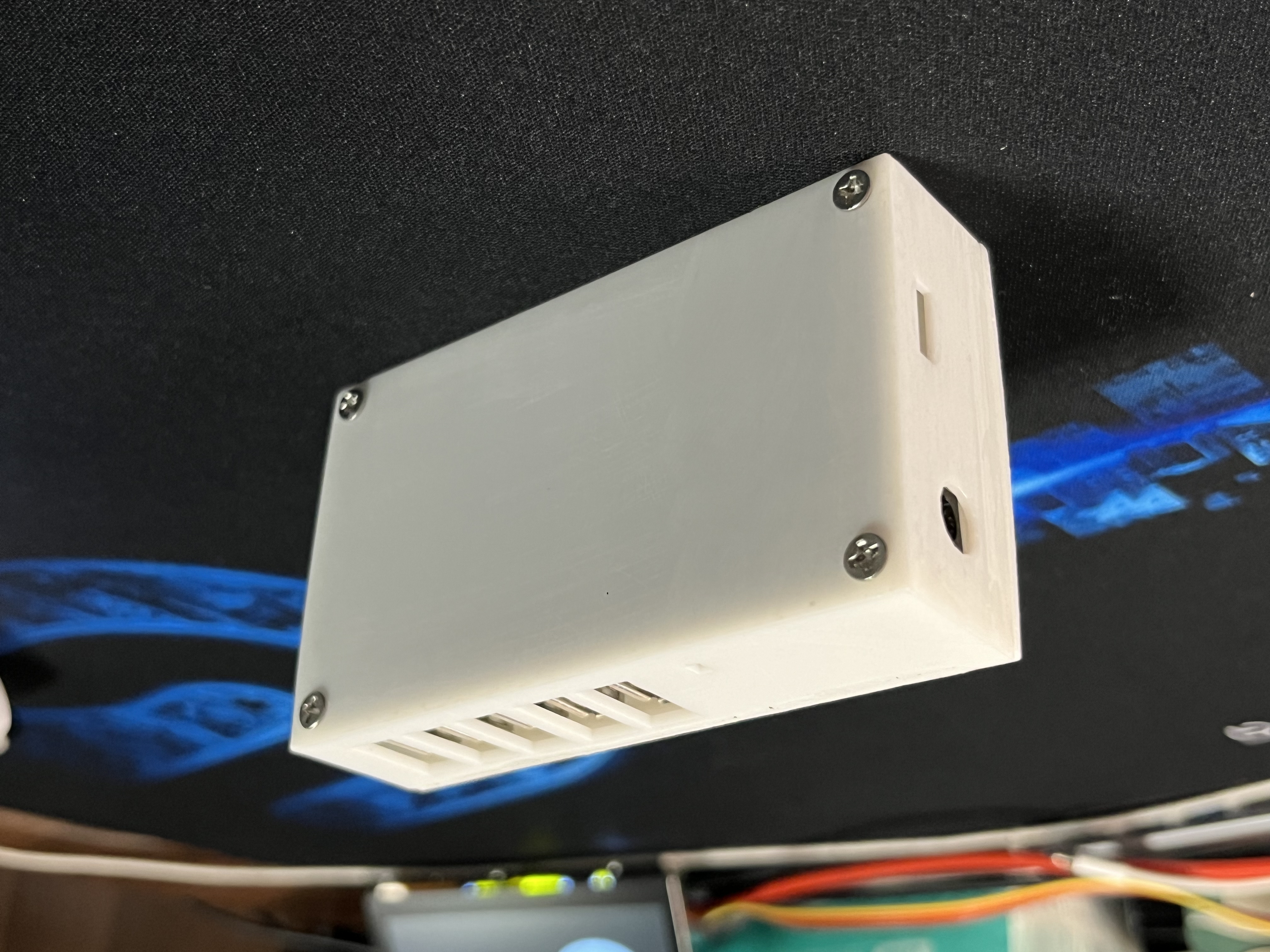
Bilibili user @wenhao_question created the 3D model of the docking station's shell and delivered it for 3D printing. The two samples are currently showing good results in testing. The model file, named "Model.stl," has been uploaded as an attachment; several photos with the shell have also been updated.
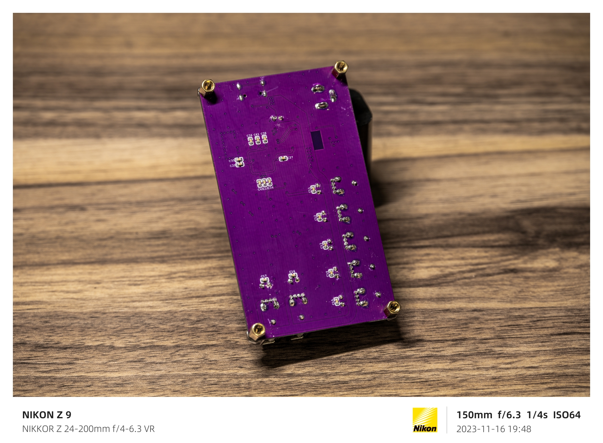
About two years ago, I made a USB 2.0 docking station using the same design, but due to a lack of experience at the time, the final product wasn't very good. Also, recently, as I entered my second year of high school, my academic workload has become increasingly heavy, leaving insufficient time to complete a large project. Therefore, I used my breaks between classes to revise the previous schematic and redraw the PCB using a professional PCB layout, resulting in this docking station.
Most mainstream computer motherboards (such as my MAG B550M Mortar Wi-Fi, which has four) only have 2-6 rear USB 2.0 ports. This is very inconvenient for electronics enthusiasts. For example, if I plug in a keyboard, mouse, printer, and oscilloscope, there's no space left on the motherboard. If I use one free front port for a USB flash drive and another for a DAPLink device, the computer's built-in USB 2.0 resources are completely exhausted. Sometimes you can use PCIe to expand USB 2.0; however, for most M-ATX motherboards, using PCIe only for USB expansion, especially 2.0, is a waste of resources. So how do we solve the problem of insufficient USB resources?
For a computer, all USB ports belong to the CPU and PCH as "USB hosts." This means that, according to the USB bus protocol, each port can theoretically cascade up to three USB expanders. Without considering cascading, expanding each USB port to seven ports would significantly increase available resources. Such a low-cost expansion dock is very user-friendly for electronics enthusiasts who need to connect a large number of low-speed peripherals such as downloaders and serial monitors.
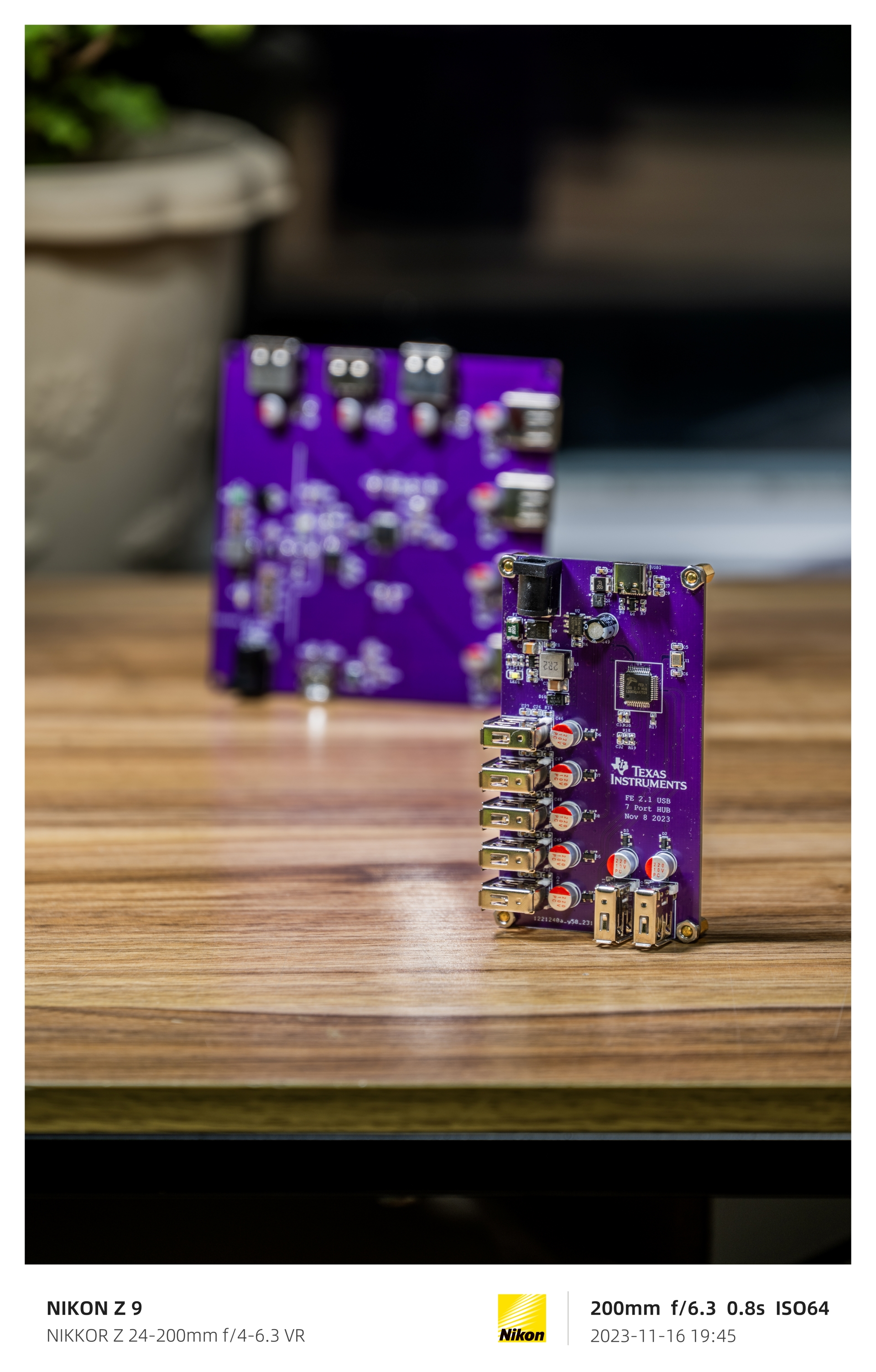
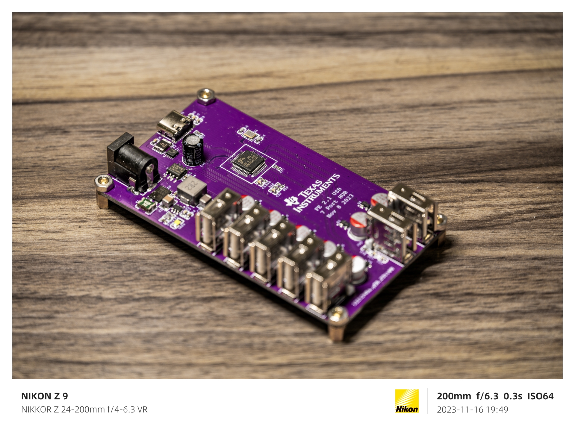
This expansion dock uses USB-C input, with all CC ports configured in RD downlink mode. This means that a USB C-to-C cable with CC cores can connect to any USB host (including MacBook) with D+ and D- data cables. Note that the original 1-meter C-to-C cable for Apple iPads only has CC cores and lacks the USB 2.0 D+ and D- cores, so it cannot be used and can only be used for charging. The 1.8-meter version is usable. This docking station is also equipped with a DC input interface with an input range of 4.5V-17V, capable of outputting a peak 5V Bus voltage of 5A to power devices on all 7 ports simultaneously, preventing overloading of the C port. Reverse current protection, reverse connection protection, and spike absorption circuitry are designed near the C port. All USB circuits are also equipped with TVS diodes, and a resettable fuse is placed near the power chip to prevent accidents. A power indicator light will illuminate after a successful connection, indicating that the docking station is working properly. The 7 downstream ports use USB-A interfaces, offering maximum versatility.
Further detailed information and a tutorial have been compiled into a 40-minute instructional video and uploaded to Bilibili; feel free to check it out! Below are some images of the finished product. Link: https://www.bilibili.com/video/BV1Zp4y1Z7b6/


The effect after the casing is installed:


 京公网安备 11010802033920号

 2200GA1G004A2HA


