I. Defects:
The coreless motor + propeller solution is inferior to the momentum wheel solution. The initial design prioritized cost-effectiveness, opting for a coreless motor + propeller. However, it was later discovered that the noise level during debugging was excessive, making it unsuitable for dormitory adjustments. Even in the lab, adjustments were only possible when no one was around. It was later found that replacing it with a momentum wheel resulted in roughly the same cost.
II. Hardware Introduction
: First Version:
MCU: GD32F103CBT6
Wireless Module: Hailink B25
Charging Chip : TP4057 Motor Driver Chip:
DRV8833
Second Version:
MCU: GD32F103CBT6
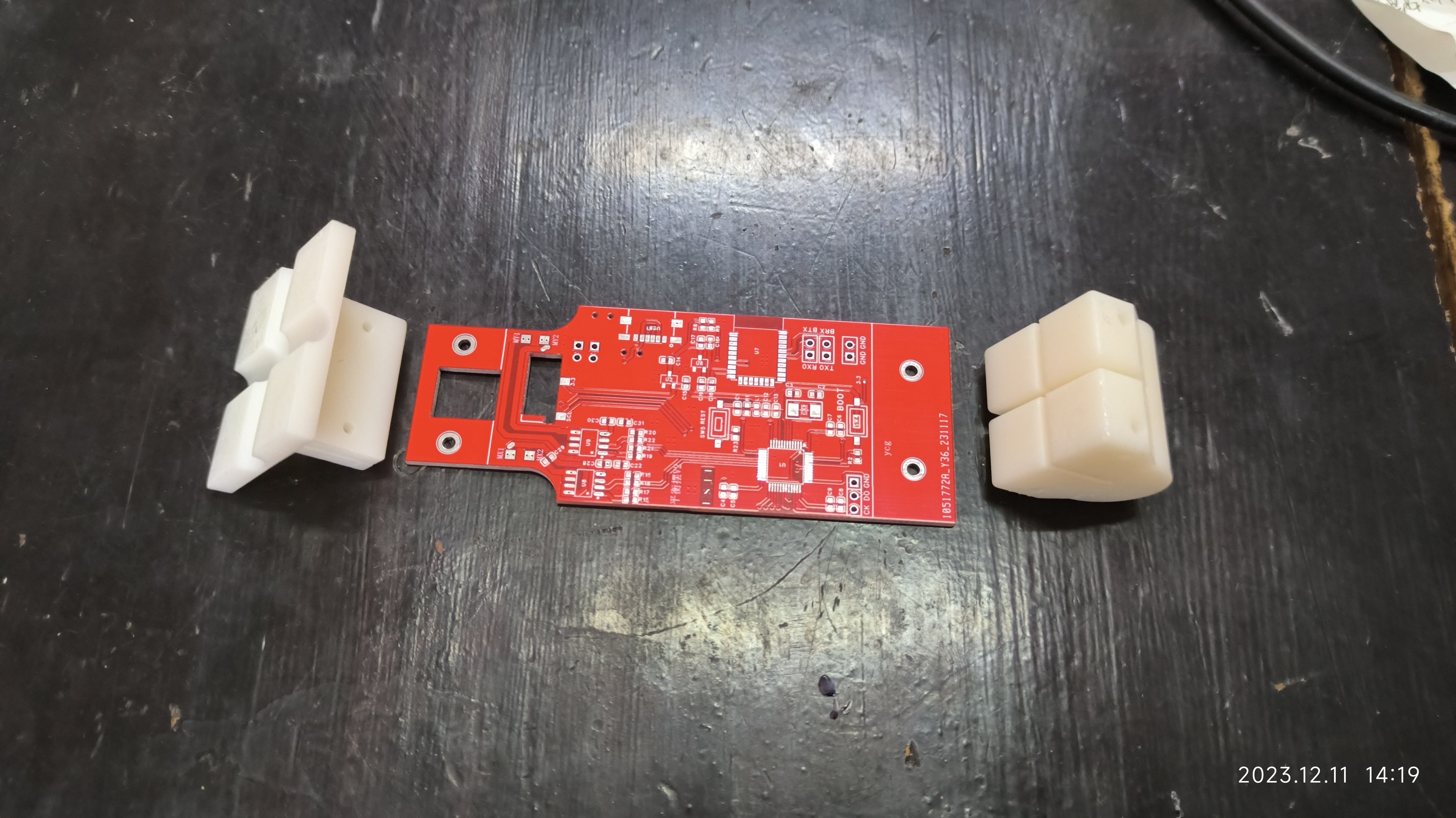
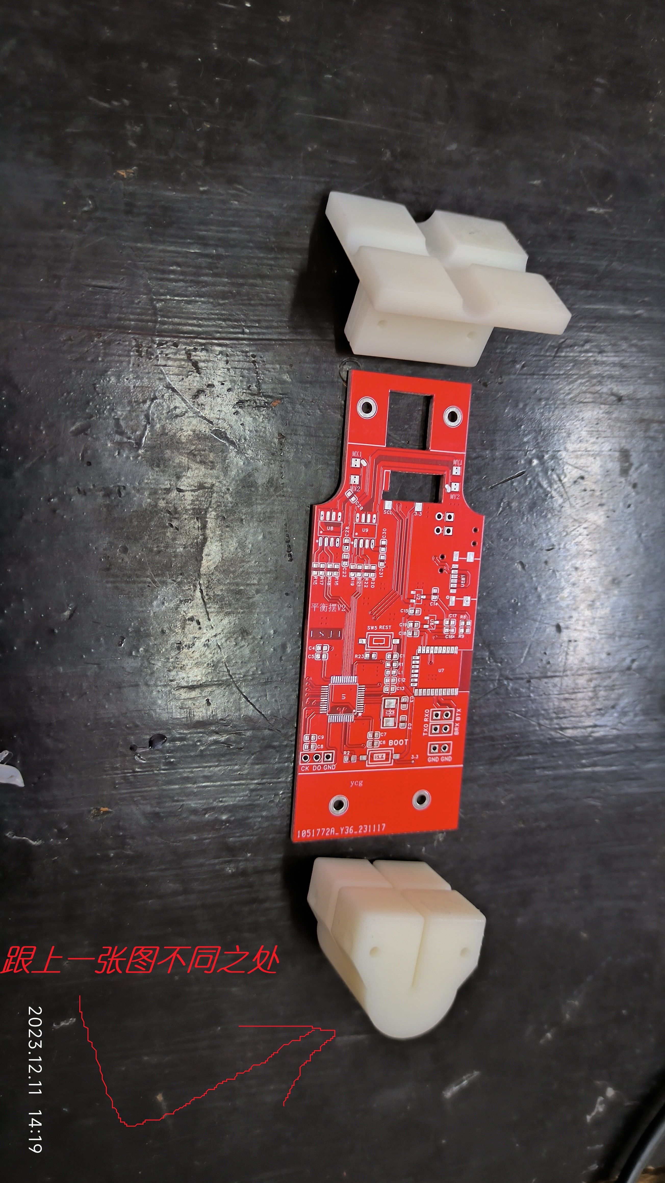
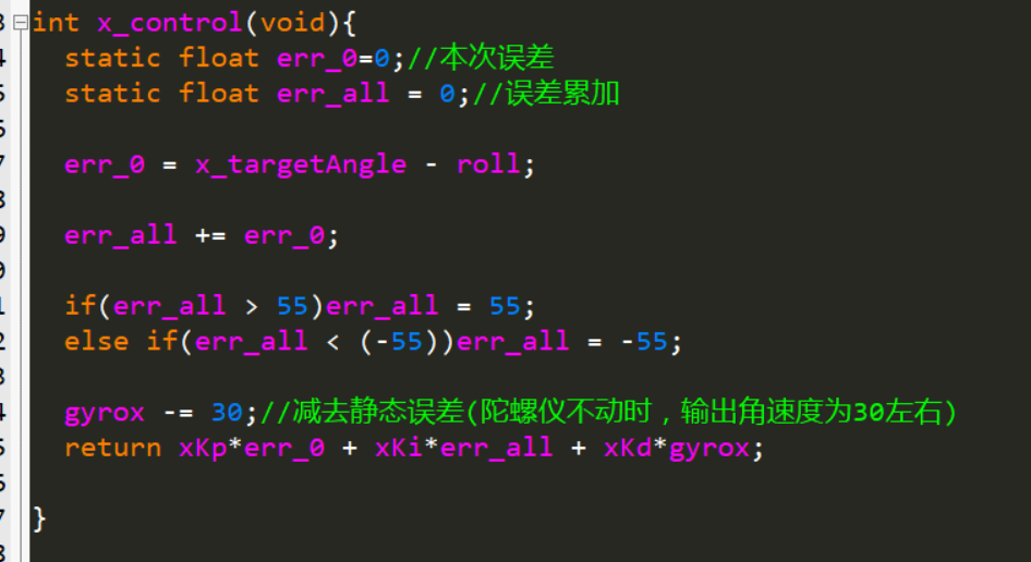
Bluetooth Module: Hailink B25 Charging Chip: TP4057 Motor Driver Chip: RZ7899 Problems with the First Version: Overconfidence; the MCU minimum system lacked a reset and boot button. This resulted in the chip not being recognized by DAP-Link after board assembly. ST-Link occasionally recognized the chip. Including reset and boot buttons would have greatly facilitated troubleshooting. Since ST-Link can download programs most of the time, I started writing the code for each part. However, when it came to driving the motor, I found that it wouldn't drive at all. I tried open-drain microcontrollers and push-pull output modes. Either the DRV8833 I bought (from the same store) was faulty, or the DRV8833 schematic was incorrect (if any experts know, please point it out). I didn't buy a new DRV8833 because I wasn't satisfied with the original board, so I just had a new board made. The second version was basically problem-free, the only issue being that neither DAP-Link nor ST-Link could recognize the microcontroller, but I could download programs via serial port and it would run normally. Why couldn't the programmer recognize the microcontroller? I suspect that the microcontroller's JTAG peripheral was burned out during soldering (but the probability is very small), or it might be a schematic problem, but I really can't think of a download circuit. What could be wrong with the schematic? I hope an expert can give me some guidance. The charging IC is a TP4057, which is a pretty good chip, supporting a maximum charging current of 500mA, but I'm using 100mA here. The Hailing Technology B25 Bluetooth module is quite good, with excellent response speed. During parameter tuning, the curves were almost real-time, and it's very easy to use. When tuning, I set the B25 on the balance pendulum to slave mode and another board to master mode. This other board was the first version, which already had a B25 module. I simply added this discarded board to the serial port module to act as a communication bridge between the balance pendulum and the PC. A more intuitive understanding is shown in the diagram below. My initial idea was to configure the balance pendulum's Bluetooth module as a slave, directly connect it to the PC's Bluetooth, and then use Python to create a virtual serial port to connect to the parameter tuning software, as shown in the diagram below. Note: The RZ7899 driver chip has the disadvantage that the driving frequency cannot be too high; it's said to be limited to 1kHz. I used 2kHz, and in actual testing, the chip overheated significantly above 2kHz (this is also mentioned in many online discussions). Its advantages are simple peripheral circuitry, wide voltage range, high current capability, and low price. III. 3D Model of Accessories: A total of three parts were made at LCSC and printed twice (my own printer is gathering dust at home). The entire balance pendulum structure looks roughly like this. When adjusting the X direction: When adjusting the Y direction: IV. PID Parameter Tuning Experience: When using PID as a control algorithm, the first thing to do is to determine whether to use incremental PID or positional PID. For specific selection, you can refer to this video: [Smart Balance Scooter: (2) Preliminary Understanding of PID Control Algorithm] [Precisely airdropped to 12:24] https://www.bilibili.com/video/BV1jW4y197fD/?share_source=copy_web&vd_source=68337adbea96c8cef50403a4b2809df6&t=744 After determining which PID controller to use, write the PID control program. Then, based on the actual phenomena of the balance pendulum, first determine the signs of the three parameters (this is very important). Method for determining the sign of the parameters: There are three parameters in total. First, understand the effect of each parameter. Proportional effect: Suppresses error . Integral effect: The longer the error exists in a certain direction, the more obvious the effect of suppressing the error . Derivative effect: Suppresses movement. Determining the sign of the proportional coefficient: Set the integral and derivative coefficients to 0, then set the proportional coefficient to a positive number. When an error occurs, if the effect is to suppress the error, then the proportional coefficient should be positive; otherwise, it should be negative. Determining the sign of the integral coefficient: Set the proportional and differential coefficients to 0, then set the integral coefficient to a positive number. When an error occurs, if the effect of suppressing the error becomes more and more obvious over time, the integral coefficient is positive; otherwise, it is negative. Determining the sign of the differential coefficient: Set the proportional and integral coefficients to 0, then set the differential coefficient to a positive number. Then move the pendulum. If the effect of suppressing your movement is positive, the differential coefficient is positive; otherwise, it is negative. In addition to the three parameters P, I, and D mentioned above, there are two more parameters: the target angle and the maximum cumulative value of the integral error. Other parameter tuning processes will not be discussed in detail. A parameter tuning video will be recorded and uploaded to Bilibili later (it will be posted in the comments after recording and publishing). Attached are today's parameter tuning notes: On December 12th, using the gyroscope's original angular velocity in conjunction with the angle, after determining the positive and negative signs of the parameters, the effect was acceptable; the pendulum could stand upright. However, the steady-state error could not be eliminated by integration, and there was a strange phenomenon that increasing the integral effect actually increased the error. At the same time, the parameters were not properly tuned, resulting in a slow response. The following test steps were performed: 1. Because the gyroscope chip outputs a non-zero angular velocity when the angular velocity is 0, causing the differential action to persist, the instantaneous angular velocity calculated by the user was used as the input to the differential term. Test results: The calculated instantaneous angular velocity changed too quickly, requiring a very large integral parameter to be effective. Furthermore, combined with other parameters, the overall control effect was not as good as using the gyroscope's angular velocity. 2. A low-pass filter was applied to the calculated angular velocity. The previous value was 0.9, and this time it was 0.1 to mitigate the rapid change in angular velocity. Test results: The differential parameter was still very large, and when it was too large, the differential action exhibited significant oscillations (it's possible the differential parameter wasn't tested correctly; in any case, a small value had no effect, and a large value caused oscillations in the differential term). The overall effect was not as good as directly using the gyroscope's angular velocity. 3. It was found that when the actual angular velocity of the gyroscope was 0, the output angular velocity stabilized around 30. Therefore, the obtained gyroscope angular velocity could be directly subtracted by 30 and input into the differential term. Test results: The static error of the differential action was eliminated, but the effect of the integral term on this basis was still rather mysterious. 4. Understanding the reason for the mysterious effect of the integral action: The test revealed that the mysterious effect of the integral action was caused by limiting the integral output, which allowed the integral input to increase significantly, resulting in a very slow integral response and the mysterious effect mentioned at the beginning (understanding this explains all the phenomena of the integral action). Therefore, the correct approach is to limit the integral input, not the output.


Test results: The overall effect is very good. With a fixed target angle (without adjusting the target angle), the parameters can be adjusted to make the system very stable with very small steady-state error. However, there are the following problems:
4.1 When the target angle is finely adjusted by 1 to 2 degrees, the effect does not change much. However, when the target angle changes significantly, although the system can balance, the steady-state error will increase. At this time, new parameters are needed to eliminate the steady-state error.
4.2 The system response speed is relatively slow. If the derivative action is weakened, the system will oscillate. Therefore, only by making the derivative action larger can the system be kept from oscillating. The resulting problem is a slow system response (which should be normal).
4.3 Launch start has been added.
4.4 The PID algorithm above controls the angle of the pendulum to the manually set target angle. An adaptive target angle can be tried to achieve a better self-stabilizing effect (e.g., when the load is increased on one side, it can automatically adjust to tilt to the other side, so that the system maintains balance at the lowest cost).
V. Program Flowchart
The program flow is relatively simple, which is to execute three tasks in parallel.

VI. Physical Demonstration
[A pendulum made of a hollow cup and a propeller - Bilibili] https://b23.tv/Vf6erXg


 京公网安备 11010802033920号

 B07243AS1


