Oscilloscope Expansion Module Overview
1. Oscilloscope Application Scenarios
An oscilloscope is an instrument for observing electrical signals. It can display electronic signals that are invisible to the naked eye through a screen, allowing us to intuitively understand and analyze the current circuit's operating state. Currently, the mainstream oscilloscopes are mainly divided into analog oscilloscopes and digital oscilloscopes. Analog oscilloscopes mainly process the input electronic signals through operational amplifiers and other means, and then output them directly to the upper and lower bias voltages of the electronic display tube. The waveform is displayed by refreshing in the left and right directions.
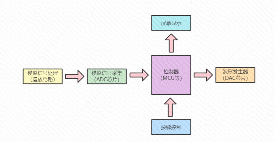
Figure 1-1 Analog Oscilloscope Digital oscilloscopes mainly acquire the processed analog signals through an ADC, and after being processed by a controller, output them to the screen for display. To facilitate analysis and recording, digital oscilloscopes account for a relatively large proportion.
Oscilloscope Expansion Module Overview
1. Oscilloscope Application Scenarios
An oscilloscope is an instrument for observing electrical signals. It can display electronic signals that are invisible to the naked eye through a screen, allowing us to intuitively understand and analyze the current circuit's operating state. Currently, the mainstream oscilloscopes are mainly divided into analog oscilloscopes and digital oscilloscopes. Analog oscilloscopes primarily process input electronic signals through operational amplifiers (op-amps) and output them directly to the upper and lower bias voltages of the cathode ray tube (CRT), creating a waveform display through horizontal refresh. (
Figure 1-1: Analog Oscilloscope) Digital oscilloscopes mainly acquire processed analog signals via an ADC, process them through a controller, and then output them to the screen for display. Digital oscilloscopes are more commonly used for analysis and recording. (

Figure 1-1: Digital Oscilloscope
) 2. The Value of DIY Digital Oscilloscopes
Compared to traditional control circuits, DIY digital oscilloscopes are more challenging, involving analog signal processing (op-amp circuits), analog signal acquisition (ADC), digital signal processing (DSP), screen interface design, waveform generator (DAC), and button function control. DIY oscilloscopes provide a good understanding of analog signal scaling and amplifier usage, digital signal processing capabilities, and microcontroller ADC, DAC, and screen UI design skills. Furthermore, the completed DIY project can be applied to real-world scenarios, which may explain the proliferation of homemade oscilloscopes.
3. Mainstream DIY Oscilloscope Solutions
Currently, the author mainly categorizes existing DIY oscilloscopes online into three types: (This classification may be somewhat biased; please refer to your own understanding.)
The first type is the professional oscilloscope: primarily using RAM as the main controller, FPGA + high-speed ADC chip for analog signal acquisition, high-speed DAC as the waveform generator, and high-precision operational amplifier preamplifier circuitry.

The second type is the practical oscilloscope: primarily using a microcontroller as the main controller, high-speed ADC for analog signal acquisition, high-speed DAC as the waveform generator, and operational amplifier control preamplifier circuitry.
The third type is the learning oscilloscope: primarily using a microcontroller as the main controller, built-in ADC for analog signal acquisition, and simple operational amplifier preamplifier circuitry.
4. Key Highlights of the Liangshanpai Development Board Oscilloscope Module
4.1 Compact and Convenient, Putting the Tool in Your Pocket
4.2 Highly Developed Software Framework, Learning Advanced Development Techniques


4.3 Simple Circuit Design, Quick Start The DIY oscilloscope
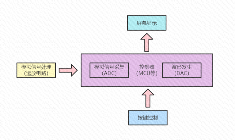
adopts a learning-level oscilloscope design scheme, using the built-in ADC and DAC of the Liangshanpai GD32F450 to create a DIY oscilloscope. (The analog circuit design incorporates deep learning and references Anfulai's open-source oscilloscope module circuits, and a usage license has been obtained from Anfulai.)
5. The Liangshanpai development board oscilloscope module features
fully open-source hardware and software functionality, allowing for free definition of more interesting functions.
Sampling Start/Stop: Starts and stops the ADC trigger timer; when paused, detailed information such as maximum and minimum values can be viewed.
Buffer Scroll Bar: Displays the acquisition status by calculating the waveform trigger position; the paused status is displayed by adjusting the offset position.
Rising/Falling Edge: Determines and displays the position when the sampled value and trigger condition are met through software comparison.
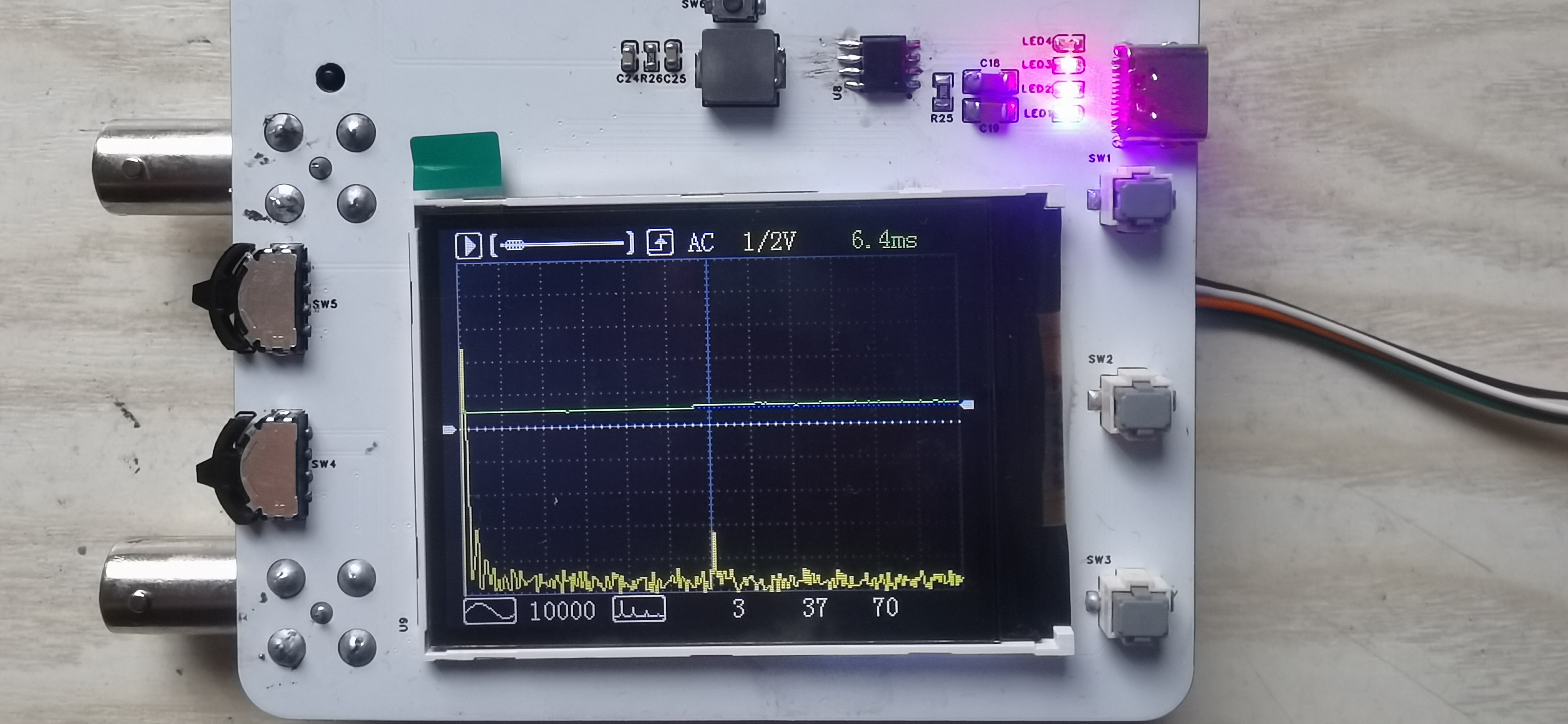
AC/DC: Controls the on/off state of the oscilloscope's pre-amplifier coupling relay via IO.
Voltage Scale: Assigns voltage values in 1/2V/div increments; controls the operational amplifier multiplier via IO using an analog switch.
Time Scale: Changes the sampling time scale by controlling the ADC trigger timer period.
Trigger Amplitude: Sets the trigger value and draws the horizontal beam position using software; indicated by a blue dashed line.
Waveform Offset: Shifts the display position vertically using software processing; indicated by a white dashed line.
Waveform display: Instead of the traditional two-point slope line calculation (neither X nor Y coordinates are used), it uses only vertical lines drawn between adjacent points, reducing the amount of code computation.
Waveform generator type: Change the single-cycle data in the DAC's buffer to automatically generate the corresponding waveform output.
Waveform generator frequency: Change the DAC's Time trigger period to automatically generate the corresponding waveform period.
FFT measurement switch: Software controls the display of the FFT spectrum waveform.
FFT frequency measurement: Calculate the frequency using the maximum frequency percentage point, which may differ slightly from the actual frequency.
FFT spectrum scaling factor: Scale the maximum value based on the value that needs to be displayed at a height of 150 pixels.
Display coordinate offset: The sampling state displays the trigger position value, and the paused state displays the manual offset position.
6. Advanced oscilloscope module of Liangshanpai development board:
Since the software framework uses Time+DMA for both ADC and DAC, if an external ADC and DAC are used for advanced development, the Time+DMA data interaction needs to be switched to the corresponding GPIO.
When using DMA+GPIO, it is necessary to use consecutive GPIOs and prevent accidental operation of GPIOs on the same bus (8/16 bits).


 京公网安备 11010802033920号

 MA-111-054-147-A5000


