Video Link:
Bilibili Video -- Function Demonstration and Introduction (Demonstration video not yet produced)
Project Introduction
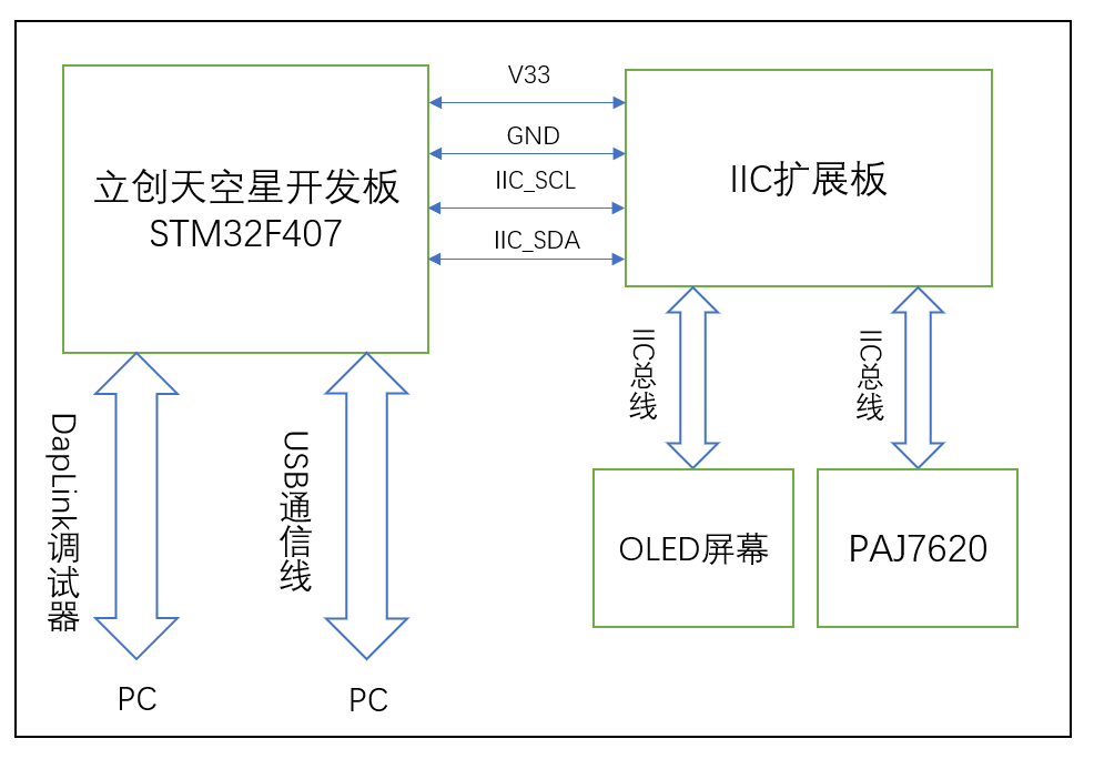
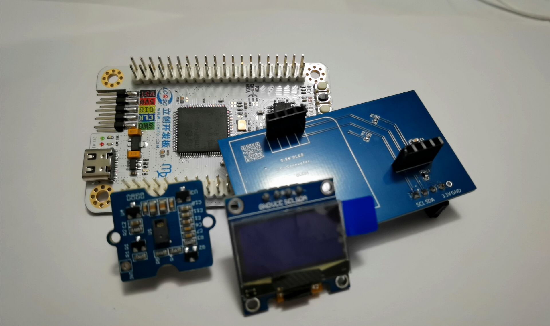
This project is a PPT electronic application based on the LCSC SkyStar development board, featuring air-based page turning. The main circuit modules used are the LCSC SkyStar development board, an external gesture recognition sensor circuit, and an OLED screen. The OLED screen displays the gesture type/page-turning action type.
Project Function
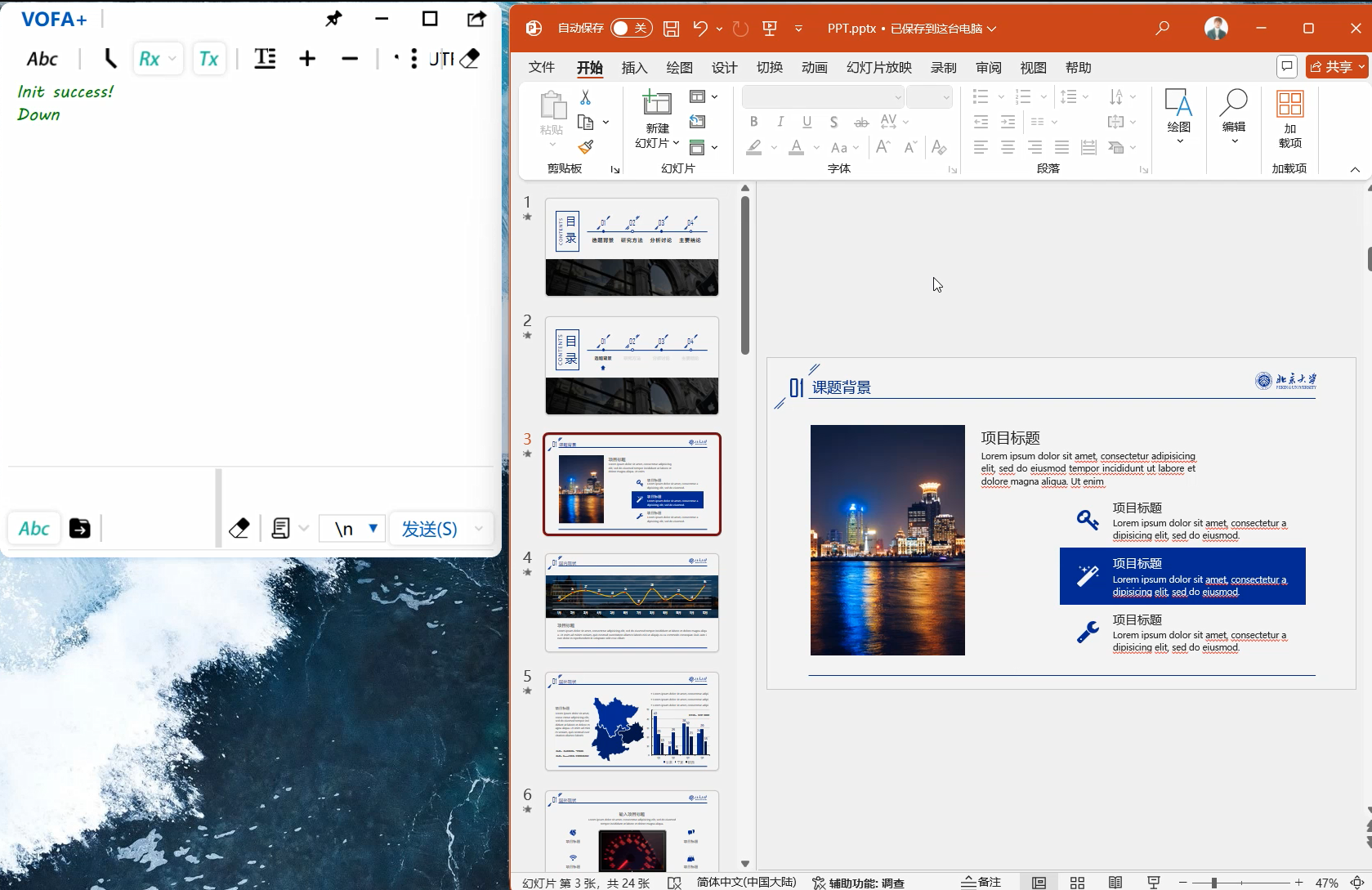
This design uses the LCSC SkyStar development board as the main control board. After the main control board's MCU collects data from the gesture recognition sensor, it sends corresponding HID commands to the PC based on the parsed gesture type to complete the PPT page turning.
1. Using JLCSC EDA, an expansion circuit board design was completed. A new gesture recognition module circuit was redesigned based on the reference application circuit of the gesture sensor IC. The module's communication interface is IIC, which also exposes an SPI communication interface. Therefore, the expansion board also exposes SPI communication pins, allowing the PAJ7620 to use SPI communication later. PCB version 1 is an expansion board design, and PCB version 2 is an independent design for the gesture recognition module
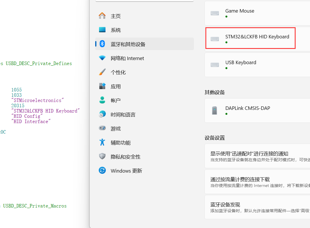
. 2. To complete the PPT page turning on the PC, the STM32 F407's built-in USB peripheral needs to communicate with the PC via a USB data cable. During the communication process, the corresponding USB protocol analysis tool can be used to parse the communication data. Correct test data parsing indicates that the USB communication is normal.
Project parameters:
This design uses the PAJ7620 gesture recognition sensor, which has accurate gesture recognition capabilities;
This design uses the STM3F407 series main control MCU, which has a USB communication interface and also has high-speed bus communication and high-speed data processing capabilities;
This design uses a 0.96-inch OLED module, and the screen driver IC is the SSD1306, a common single-chip microcontroller screen module with advantages such as simple driving and small image array data volume.
Principle analysis (hardware description):
PAJ7620 IC internal structure diagram.
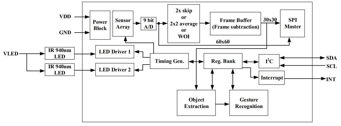
Sensor introduction:
PAJ7620U2 The chip is an optical array sensor from PixArt, integrating an LED with a built-in light source and ambient light suppression filter, a lens, and a gesture recognition sensor. It can operate in dark or low-light environments and features gesture recognition and object proximity detection supporting nine gestures. The gesture recognition module uses an III2C interface and can be programmed and controlled using corresponding library functions. The signals returned by the gesture recognition module can be used as control signals for the robot, enabling robot control. The built-in recognition algorithm is quite intelligent, freeing hands from cumbersome button presses. The gesture recognition sensor can be used in non-contact control scenarios such as non-contact mice, smart homes, automotive click device control, and robot interaction. The types of
recognizable gestures are shown in the following figure:

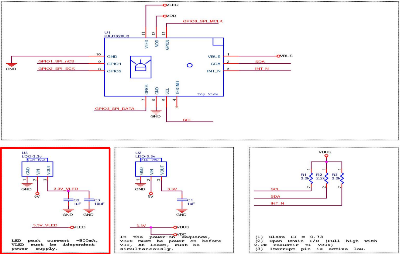
Example Figure 1 – PAJ7620 Reference Design Circuit:
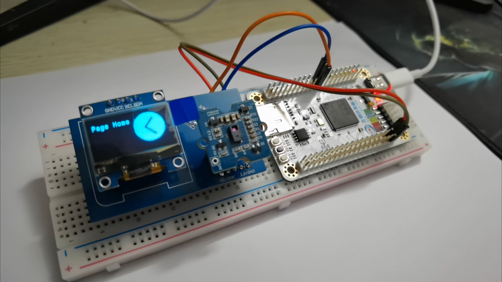
The software program adopts both hardware IIC and software IIC driving methods. Software IIC allows flexible switching of drive pins, but the screen refresh rate is not as fast as hardware IIC. The above two driving methods can be switched with a single key using a macro definition flag in the main.h header file.
Hardware IIC connection pins:
VCC<->V33
GND<->GND
SCL<->PB8
SDA<->PB7
Software IIC connection pins:
VCC<->V33
GND<->GND
SCL<->PD10
SDA<->PD12
Devices and programming tools used:
STM32CubeMX version 6.12.0,
MDK Keil version 5.38.0,
LCSC Skystar development board main controller model STM32F407VGT6,
gesture recognition module IC model PAJ7620,
OLED screen IC model SSD1306,
DapLink debugger version daplink_V1.0
Software code
example code:
enum keycode{ //keyboard function code enumeration
pageUp=0x4B, //page up
pageDown=0x4E, //page down
pageHome=0x4A, //jump to home page
pageEnd=0x4D //jump to end page
};
void keyboard_code(uint8_t kc){ // Keyboard HID report descriptor
uint8_t HID_Buffer[8] = {0}; // Keyboard send data buffer size is 8, mouse is 4
uint8_t HID_Buffer_clean[8] = {0};
HID_Buffer[0] = 0x00;
HID_Buffer[1] = 0x00;
HID_Buffer[2] = kc;
USBD_HID_SendReport(&hUsbDeviceFS, HID_Buffer, sizeof(HID_Buffer));
HAL_Delay(200);
USBD_HID_SendReport(&hUsbDeviceFS, HID_Buffer_clean, sizeof(HID_Buffer_clean));
HAL_Delay(200);
paj_update_flag=0;
}
if(Gesture_Data !=0)
{
paj_update_flag=1;
switch (Gesture_Data)
{
case PAJ_UP:
printf("Up
"); //Note that the USB is connected to the PC
//k_code=pageUp;
keyboard_code(0x4B);
ssd1306_SetCursor(2, 8);
screenClear();
drawPicture(image_c,0);
ssd1306_WriteString("Page Up", Font_7x10, White);
break;
case PAJ_DOWN:
printf("Down
");
//k_code=pageDown;
keyboard_code(0x4E);
ssd1306_SetCursor(2, 8);
screenClear();
drawPicture(image_d,0);
ssd1306_WriteString("Page Down", Font_7x10, White);
break;
case PAJ_LEFT:
printf("Left
");
k_code=pageHome;
keyboard_code(0x4A);
ssd1306_SetCursor(2, 8);
screenClear();
drawPicture(image_aaa,0);
ssd1306_WriteString("Page Home", This project has been open-sourced and uploaded to Gitee, link below (https://gitee.com/quansirx/gesture-for-page-flip).
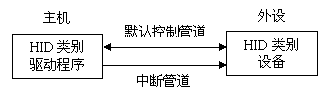
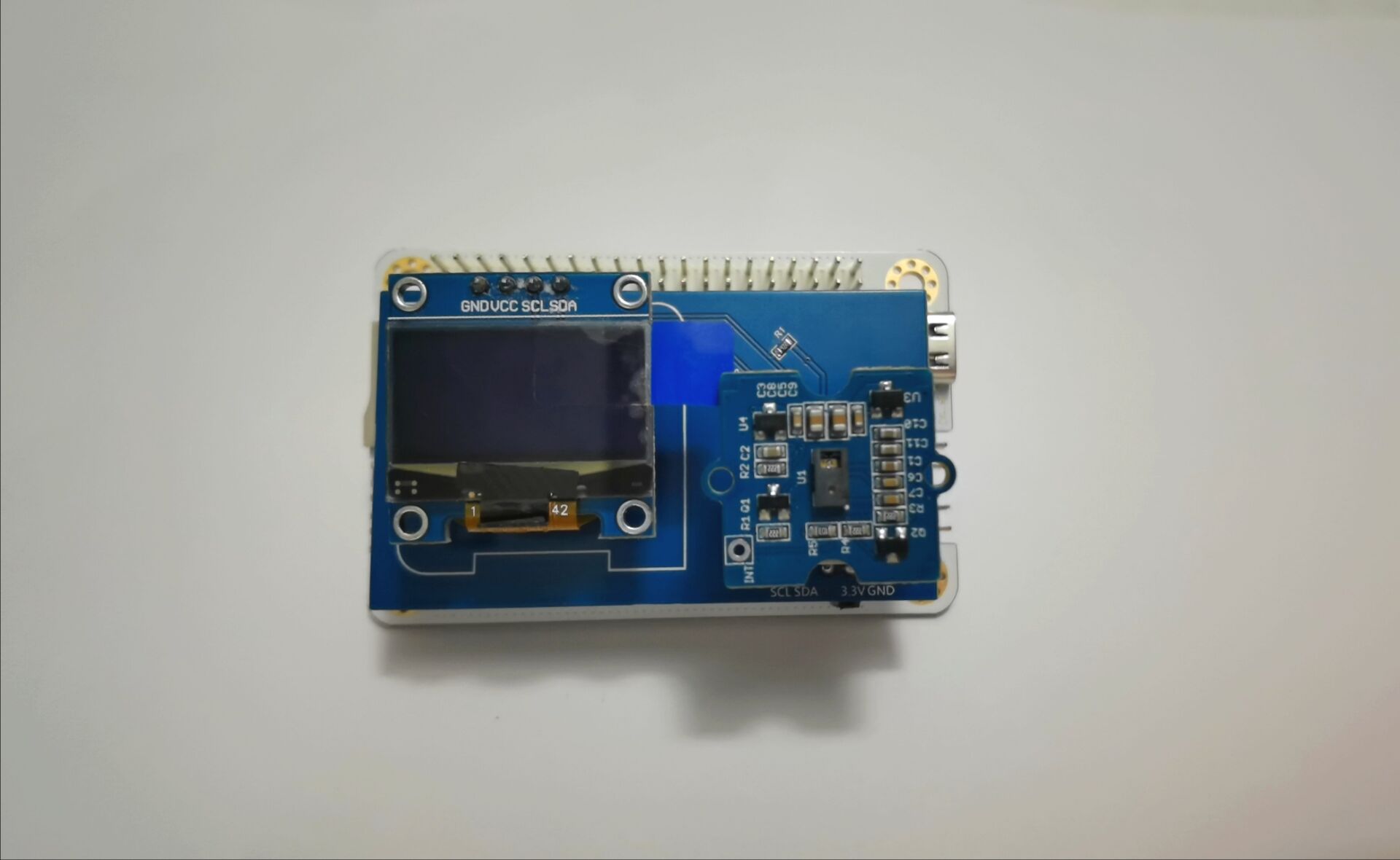
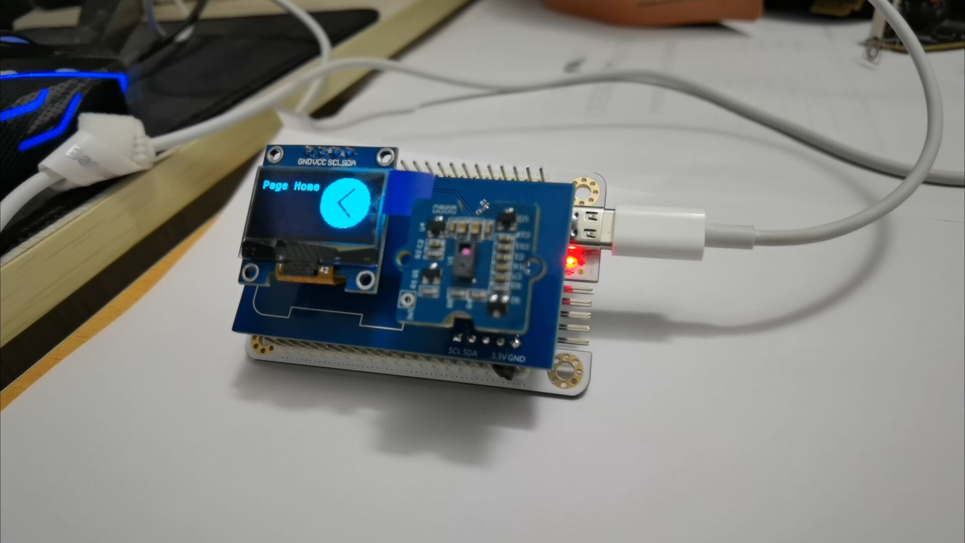
Introduction to USB HID Protocol: HID (Human Interface Device) is a common device type in USB devices, directly interacting with humans, such as keyboards , mice, and joysticks. HID devices are relatively inexpensive compared to other USB devices. Furthermore, HID devices do not necessarily require human-computer interaction; any device conforming to the HID category specification is an HID device. Windows operating systems were the first to support HID devices. Windows 98 and later versions have built-in drivers for HID devices, which applications can directly use to communicate with the devices. When designing a USB computer peripheral, if an HID type device meets the requirements, it can be designed as an HID type device. This avoids the complex writing of USB drivers and directly utilizes Windows operating system's support for standard HID type USB devices. HID devices are characterized by storing exchanged data in a structure called a report, and the device firmware must support the HID report format. The host transmits and receives data by controlling and interrupting transmissions and requesting reports. The report format is very flexible. Each transaction can carry small or medium amounts of data. Low-speed devices have a maximum of 8 bytes per transaction, and a report can use multiple transactions. Full-speed devices have a maximum of 64 bytes per transaction , and high-speed devices have a maximum of 1024 bytes per transaction. In addition to transmitting data to the host, an HID device also receives data from the host. Any device that conforms to the HID category specification can be an HID device. Besides the HID interface, the device may also include other USB interfaces. For example, a video display device might use an HID interface for software control of brightness and contrast, while using a traditional video interface to transmit the data to be displayed. A USB speaker might use real-time transmission to play audio while using an HID interface to control volume, bass, etc. Important Notes: The following are key points or common mistakes to pay attention to during design and production. When driving the USB HID to establish communication with the computer, pay attention to the HID report descriptor settings; during circuit board design, pay attention to the pull-up IIC bus, because the IIC device output is open-drain; when driving the OLED screen, remember to clear the screen first, and then draw the text and image content. Assembly Process Physical Framework Diagram : Figure 1: Physical Assembly Diagram; Figure 2: Running Effect Diagram (Software IIC) ; Figure 3: Running Effect Diagram (Hardware IIC) ; Figure 4: Running Effect Diagram; Figure 5: Running Effect Diagram. Finally, to summarize briefly, considering that the PAJ7620 has an SPI interface, it is feasible to redesign the PAJ7620 circuit using JLCPCB EDA and bring out the SPI communication interface. Due to a shortage of PAJ7620 components, only the expansion circuit board was prototyped. The VCC and GND pins on the expansion board did not align with the development board's pin headers. Therefore, a "flying wire" method was used: a small copper-clad area was cut out of the expansion board, and a row of female GND pins was soldered onto it. Finally, the female pins were connected to the development board's GND, resolving the misalignment issue between the expansion board and the development board's slots. The drawback was that the large copper-clad area on GND made it difficult to apply solder to the scraped copper area. Eventually, the solder adhered after continuous heating of the scraped copper area with a soldering iron. The circuit design is open-source on the JLCPCB open-source hardware platform, and the source code has been uploaded to the Gitee repository. Interested electronics enthusiasts can check it out.


 京公网安备 11010802033920号

 240-032-2-21PCF6J7-18S


