1. Can solder various IC chips [UIDCUIDFUIDUFUIDM1].
2. LEDs and chips are connected in parallel; both LEDs and current-limiting resistors are 0805 packages.
3. Positive and negative terminals for chips and LEDs can be ignored; soldering is fine.
4. LED color is arbitrary; current-limiting resistors from 50-100Ω are acceptable.
5. Reference and inspiration ; thanks to predecessors.
6. Step-by-step tutorial on drawing arbitrary graphic outlines.


=== ...
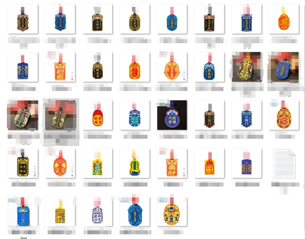
Gerber_Commander of the Embroidered Uniform Guard_2024-02-07.zip
PDF_Year of the Dragon Chinese Style Dragon Head NFC Card [Jinyiwei] - IC Card 13.56MHz.zip
Altium_Year of the Dragon Chinese Style Dragon Head NFC Card [Jinyiwei] - IC Card 13.56MHz.zip
PADS_Year of the Dragon Chinese Style Dragon Head NFC Card [Jinyiwei] - IC Card 13.56MHz.zip
BOM_Year of the Dragon Chinese Style Dragon Head NFC Card [Jinyiwei] - IC Card 13.56MHz.xlsx
91681
TPA3116D2 amplifier board supports LDAC and USB sound cards
The Qualcomm QCC3084 Bluetooth 5.4 + TPA3116D2 solution, USB PD power supply, the entire board supports a maximum of 20V operation, a maximum dual 40W, and can operate without heat dissipation when paired with dual 10W Harman Kardon full-range mini speakers.
Note: The original design was for Altium Designer 24. Considering the target audience, it was manually ported (re-drawn) to JLCPCB EDA, discarding some unnecessary components.
There are some differences from the original AD24 project.
Production process and introduction video: https://www.bilibili.com/video/BV1fCxqebEiP/
AD24 open source files can be found in the video introduction section
. I. Basic Parameters
Power Supply: USB PD 2.0/3.0, 9-20V (can directly use a USB-C connector without data to input DC power, maximum 24V)
Output Power: 40W/20W*2 (20V power supply, 4 ohms/8 ohms), 15W/7.5W*2 (12V power supply, 4 ohms/8 ohms), please refer to Fig. 13 and Fig. 14 in the TPA3116D2 datasheet for details.
Input Signal: USB: UAC1.0 maximum 96KHz/24bit, driverless for win10/win11/Android/iOS/MacOS/Linux Bluetooth: Bluetooth 5.4, LDAC/aptX/aptX-HD/aptX adaptive (Bluetooth priority)
PCB size: 65.8x30 (mm), height depends on the actual height of the electrolytic capacitors and the height of the heatsink.
II. Circuit Description
2.1 The Bluetooth module is Tianjiarun's SJR-BTM384 (QCC3084). The original AD24 project used Anlang Technology's AL3084. The two are incompatible in pins and sizes and cannot be used interchangeably. Because Anlang Technology's AL3084 module has slightly poor USB compatibility (there is a chance of prompting insufficient USB resources when connecting to a USB HUB), it was replaced with Tianjiarun. The price difference between the two is not significant. Bluetooth priority means that when both USB and Bluetooth are connected simultaneously, the Bluetooth audio stream will be played.
2.2 The USB PD spoofing is CH224K, available at LCSC online store. It uses a single resistor configuration mode, and the default circuit diagram requests 12V (R8=24K). If 20V operation is required, simply unsolder R8. Please refer to page 3 of the CH224 datasheet for details. If you don't want to buy a GaN charger, you can directly buy a Type-C cable, cut it, connect the red wire to the positive terminal of the power supply, and the black wire to the negative terminal. DC power can also be used. There is no additional identification circuit designed here; 9-24V is acceptable. Just make sure the positive and negative terminals are not reversed.
2.3 The amplifier circuit is a TPA3116D2. A heatsink can be added as needed. If using a 12V power supply to drive speakers no more than dual 15W, theoretically, a heatsink is not needed (in practice, it doesn't get hot to the touch). A recommended heatsink size is 22*13*11MM (available at Youxin Electronics, https://item.taobao.com/item.htm?id=535408058590). For gain and power limiting settings, please refer to the TPA3116D2 datasheet. If you are unsure of the purpose of these functions, it is recommended not to modify them. The gain is 26dB (20x), which matches the output signal level of the QCC3084. Since I don't use LCSC EDA much, I'm not sure how to represent NC, so R8 is set to request 12V. For a gain of 26dB, it's recommended to use a 20V power supply (i.e., don't solder R8), otherwise the 26dB gain + 12V power supply will cause distortion after the volume exceeds halfway.
2.4 The power switch is a P-channel MOSFET. Shorting the PWR pin on the front of the PCB will start the power supply. If you need automatic startup, short the MOSFET DS or directly solder PWR together using a jumper wire.
2.5 The power indicator is constantly lit (near the power input USB-C port; it will light up as long as the PD receives voltage, regardless of whether PWR is shorted). The Bluetooth indicator (near the data input USB-C port) is dual-color: blue indicates Bluetooth is connected, slow blue flashing indicates not connected, fast blue flashing indicates entering pairing mode, and green indicates USB is connected.
2.6 No volume potentiometer is provided. Please adjust the volume using a computer or mobile phone (because potentiometers consume a lot of PCB space, this design prioritizes small size, and potentiometers have poor durability; over time, the slider may become unresponsive).
2.7 The terminal block is KF250-3.5-4P-1, which can accommodate wires with a maximum outer diameter of 3mm. A conductor cross-sectional area of 1.5mm² or less is recommended.
2.8 The PCB has 4 layers; layer stack-up and impedance are not critical. USB 1.1 12Mbps does not require impedance considerations; if it connects, it works.
2.9 USB-C does not support mixed use; that is, signal and power inputs are separated. The port marked "Power" on the back is for power input and does not support signal input. The port marked "DATA" on the back is for signal input and does not support power input, but it includes a UFP identification resistor. It can directly connect to a laptop or mobile phone using a dual-C cable to transmit UAC protocol audio data. Because there is no physical power supply, it will not steal power from the computer or mobile phone. (
Too long, don't read version):
If you are using 20V power, do not solder R8 (see the USB_PD diagram, default is 24K). Maximum power is 40W (4 ohms) for both, and 20W (8 ohms) for both.
If you are using 12V power, please modify the resistors as follows: R25 = do not solder, R26 = 5.6K, R24 = 24K (R24 is recommended to be changed, but not changing it is not a big problem). Maximum power is 15W (4 ohms) for both, and 7.5W (8 ohms) for both.
Some parts of the explanation may not be clear; please refer to video P2 for circuit explanation. If you still have questions, please leave a comment or send a private message. I don't check JLCPCB messages frequently.
PDF_TPA3116D2 Amplifier Board Supporting LDAC and USB Sound Cards.zip
Altium TPA3116D2 amplifier board supporting LDAC and USB sound cards.zip
PADS_TPA3116D2 amplifier board supporting LDAC and USB sound cards.zip
BOM_TPA3116D2 Amplifier Board Supporting LDAC and USB Sound Cards.xlsx
91682
Guangdong University of Technology NFC Card (Campus Map Version)
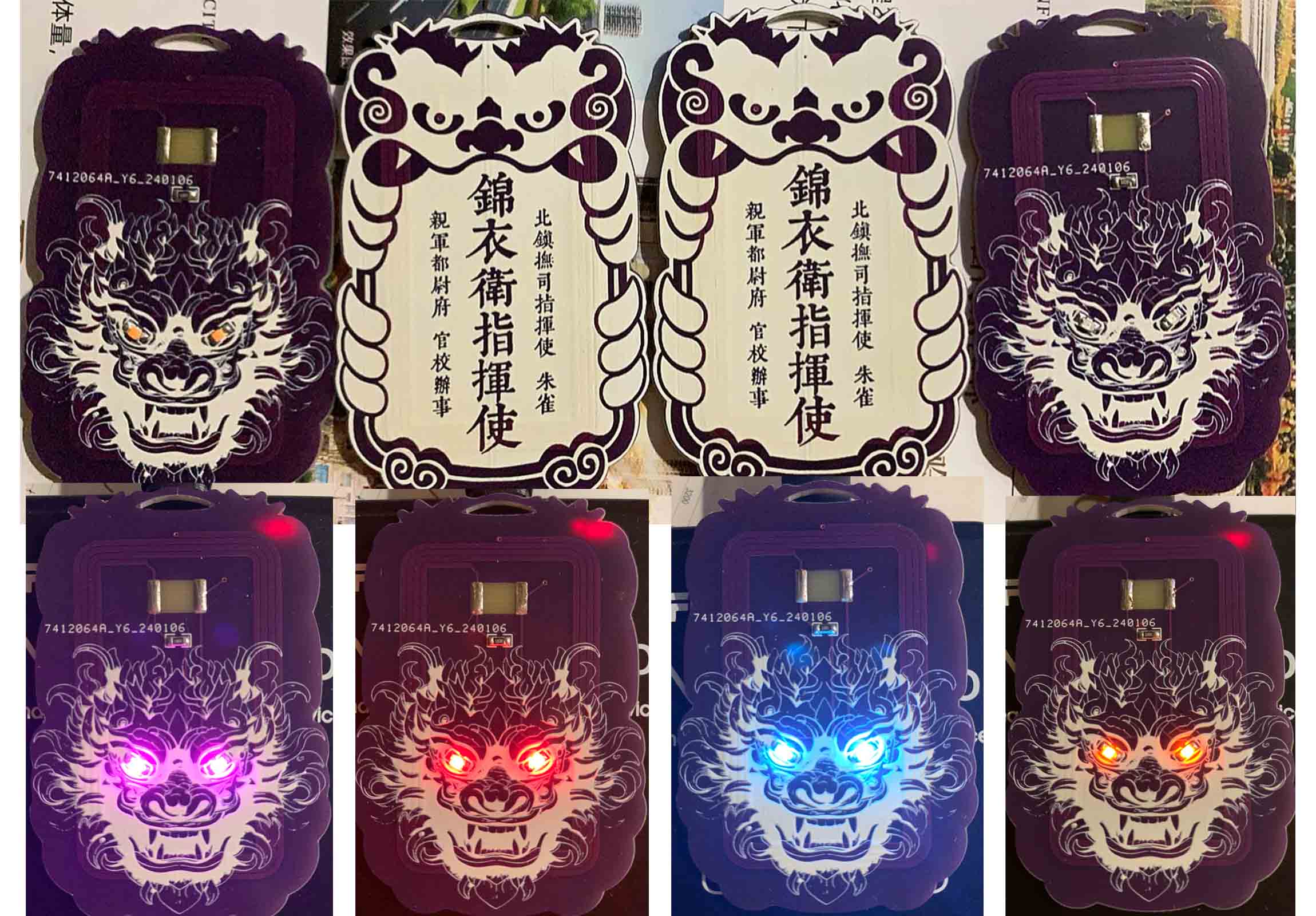
Creative onboard antennas for PCBs that meet national standard dimensions and have actual NFC functionality; UID or NFC chips can be soldered on to use NFC functionality.
This schematic design describes
an NFC card with actual circuit functionality. It can be used with other NFC cards such as UID cards to function as public transport cards, Yangcheng Tong cards, Lingnan Tong cards, and access control cards. For details, please search "UID card" on Baidu (UID cards cost an average of 0.2-0.6 yuan each on Taobao). It
can also be used with NXP chips to function as an NFC business card, enabling operations such as scanning to connect to WiFi, add WeChat, and open websites. The chip model is NT3H1101W0FHKH (average price on Taobao: 3-5 RMB/chip).
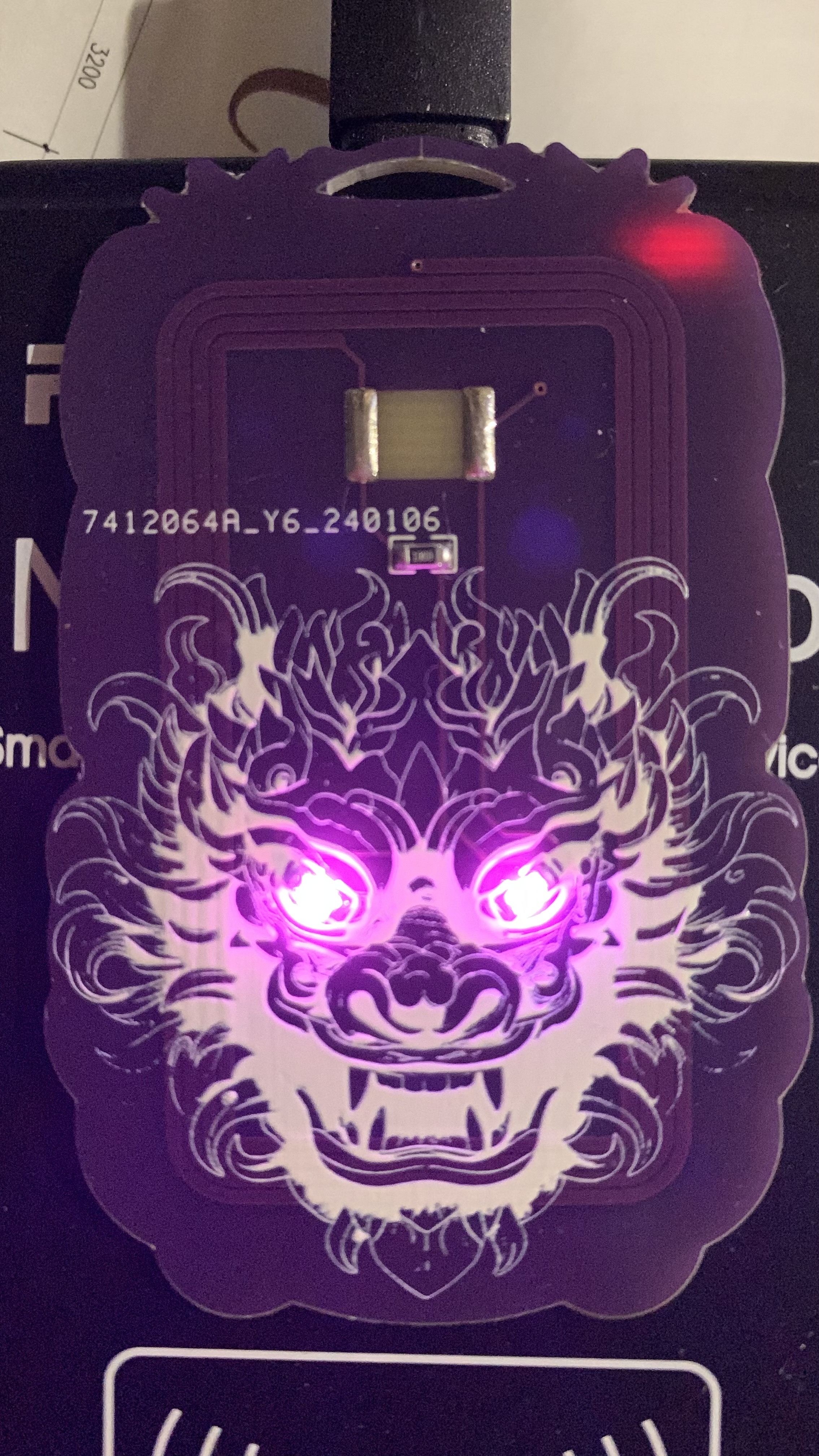
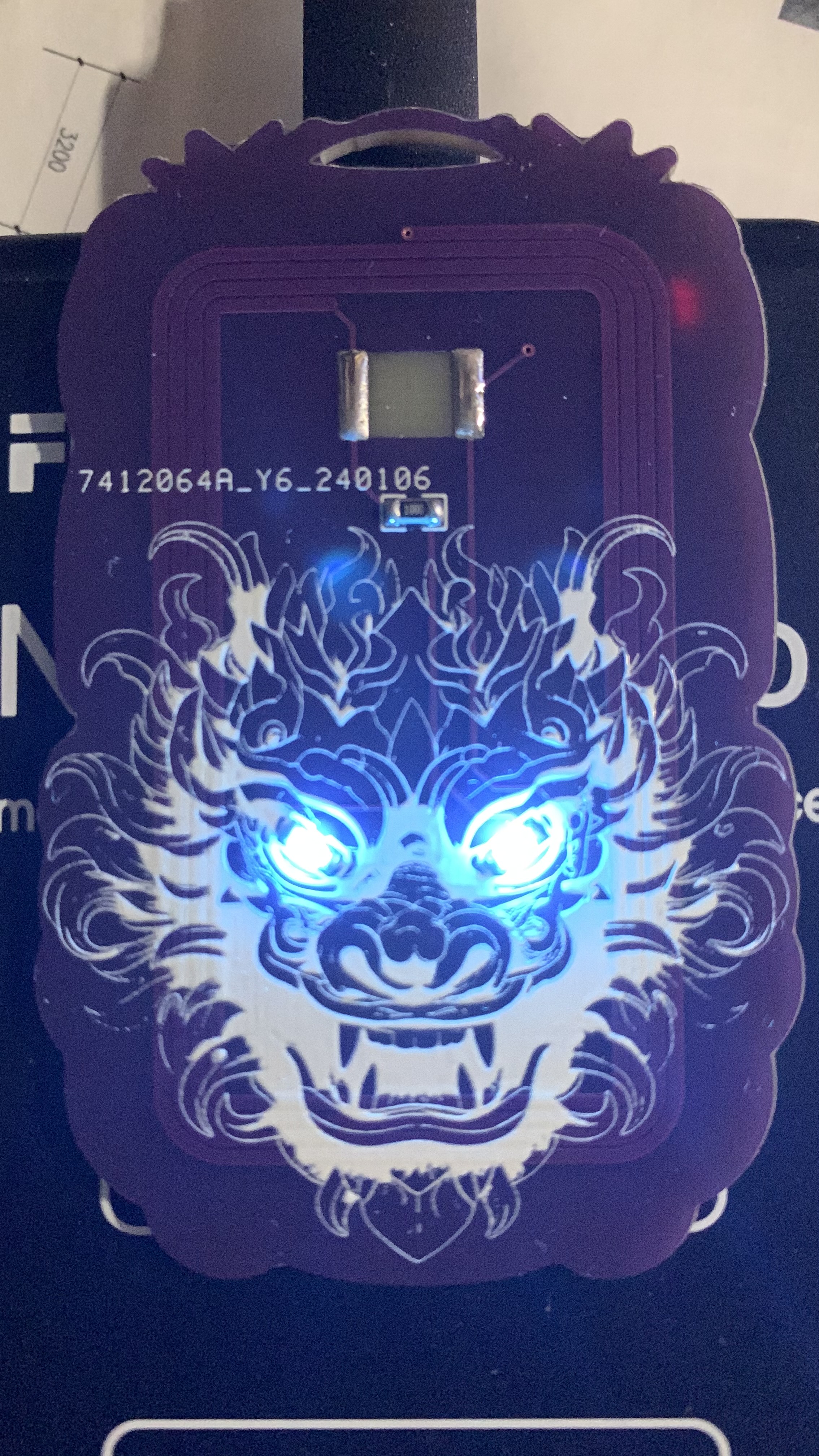
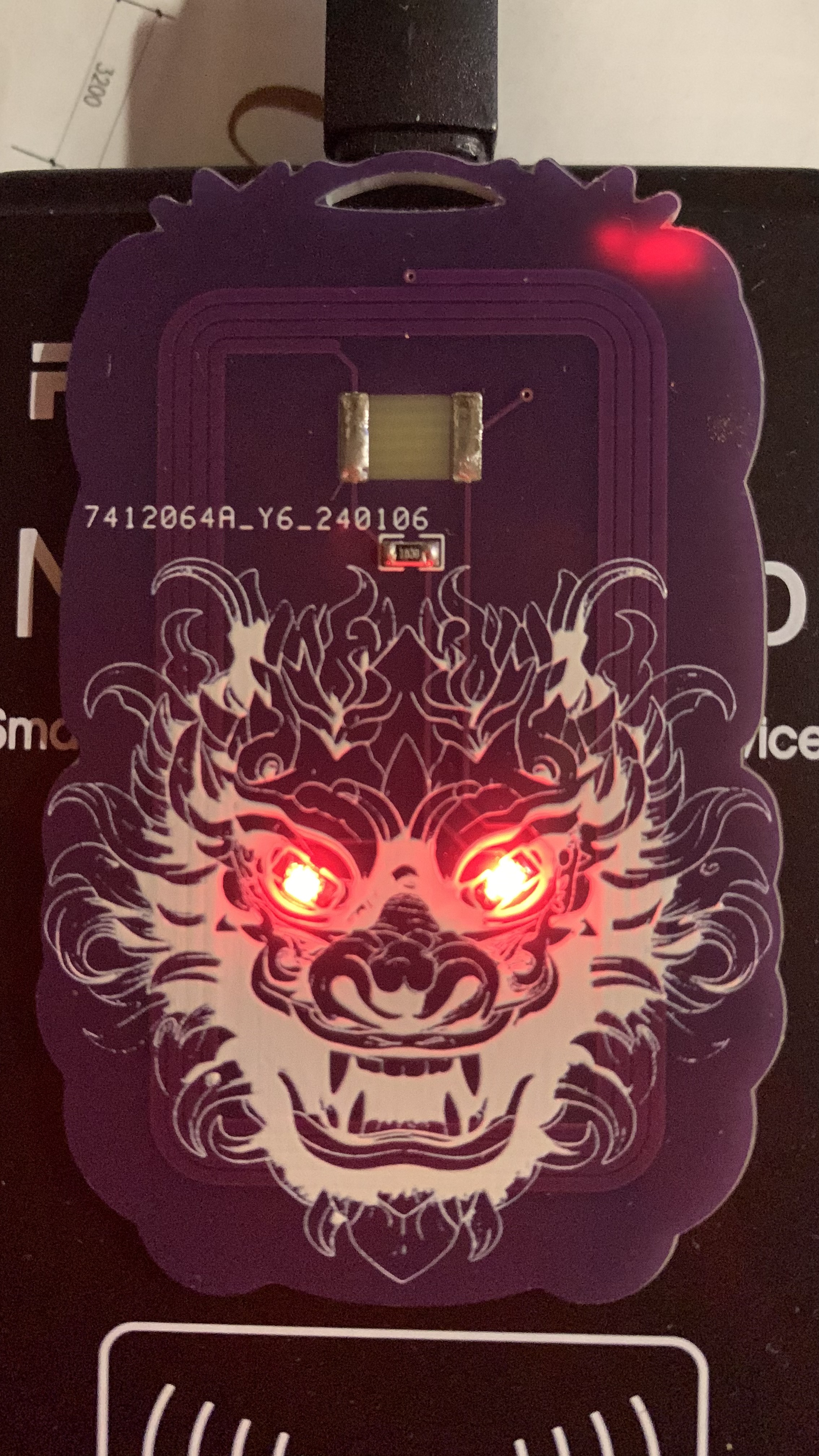
LED lighting circuitry has been added; the building information is represented by LEDs, which can be soldered on to work with card readers or wireless charging modules, allowing the LEDs representing the building to flash or remain constantly lit.
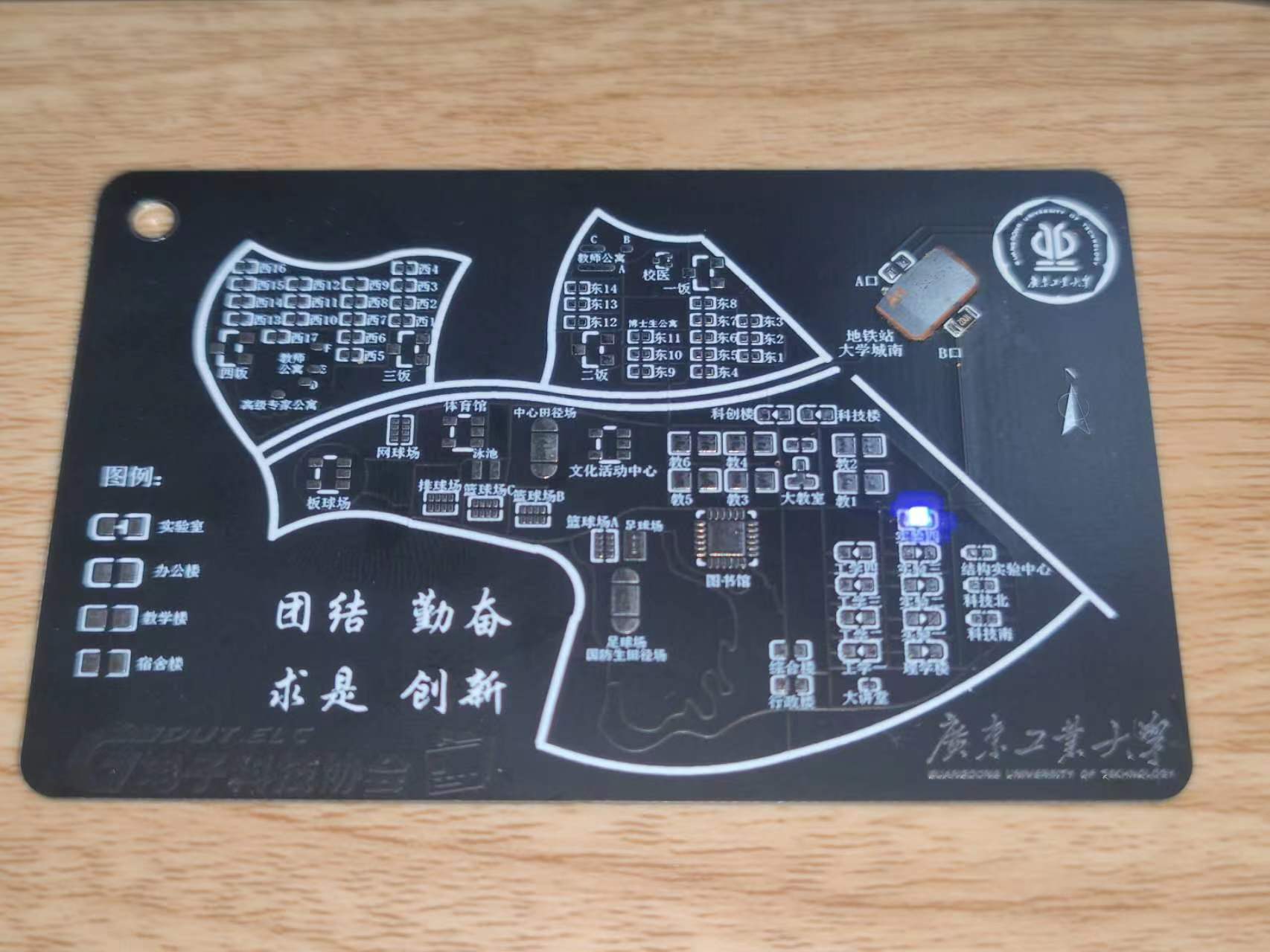
The PCB design conforms
to the People's Republic of China National Standard GB/T14916-2006 (ISO 7813) "Identification Cards - Physical Characteristics," specifying an integrated circuit card size of 85.60 × 53.98 mm (3.370 × 2.125 inches). Its aspect ratio is close to the golden ratio (1.618:1), and the corner radius is 3.18 mm. Therefore, this card can easily fit in a wallet, similar in size to a bank card or public transport card. It is recommended to choose a 0.8mm thickness (close to the ISO bank card standard of 0.76mm) for the PCB design
, along with standard M3 holes for easy use as a keychain.
The silkscreen and wiring on the front are designed according to the map of Guangdong University of Technology's University Town campus, and can be used with LEDs to illuminate the buildings when a card is swiped. The back features a 6cm ruler and decorative silkscreen printing. The overall design balances practicality and aesthetics.
Software instructions:
Any NFC function involves programming. There are two types of NFC: business card cards and function cards (see the notes below for details). Without programming, the phone can only read the card but cannot perform any operations (actually, it's more accurate to call it rewriting chip information, but for ease of understanding, we'll refer to it as programming). This is a design issue related to the NFC principle. Therefore, after soldering, you can test the circuit by touching it with an NFC-enabled phone (make sure to turn off the phone's Do Not Disturb function in the NFC settings). If the NFC is recognized, the circuit is successful.
The business card function can be done with a regular Android phone with NFC. The installation package is in the attachment; it's the .apk compressed file. You can directly use this mobile app to write the NFC card information onto the pre-soldered circuit board. The operation is very simple: after downloading and opening the app, you should understand how to use it. Just edit the information, place the card against the phone, and the writing process is complete.
For functional cards, a writer is required, or you can cut the physical card and remove the chip for soldering. Blank UID cards can be used with PN532 to write programs. Specific methods are widely available online; a quick search will yield results.
Physical demonstration
photos of the 2024v2
(due to the use of color silkscreen printing, the board thickness could not be 0.8mm, and was 1.6mm)
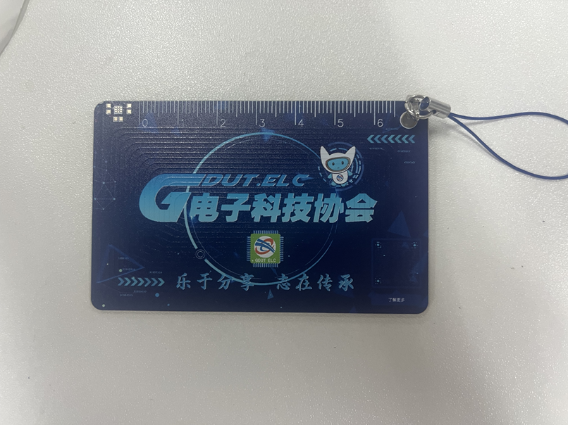
and photos of the v1
(due to manufacturing defects at the time, the silkscreen printing on the board used for the photos has slight flaws)
are provided. For v1 board fabrication, a 0.8mm board thickness is recommended. Add customer-defined characters at the designated location (the location is in the Doraemon business card and does not affect the appearance).
Notes on
LED function: When soldering, solder the LEDs to the functional buildings advertised. For example, if the Guangdong University of Technology Electrical Engineering Association headquarters is in Experiment 4, solder to Experiment 4. Do not solder elsewhere. It is recommended to solder only one LED. In the actual circuit, LEDs are connected in parallel, so multiple LEDs can be soldered. The soldering direction is irrelevant. When there are two or more LEDs, one can be soldered in the forward direction and the other in the reverse direction to achieve alternating LED blinking. Only the Experiment Building, Engineering Building, College Building, and Science and Technology Innovation Building have this LED illumination function. When using LEDs, in addition to soldering LEDs for the corresponding building, you also need to solder current-limiting resistors R1 and R3. The resistance value affects the LED brightness; a 4.7KΩ resistor is recommended. You can adjust the resistance value to adjust the LED brightness according to the actual situation. Normally, the LED blinks with the power supply frequency.
However, when soldering U2, the LED also has a constant-on mode. In this mode, solder R2 and R4 with the same resistance values as R1 and
R3 above. The LED is soldered according to its orientation; be sure to solder it in the correct orientation according to the silkscreen markings. (Note that R1 and R3 cannot be soldered in this mode; R2, R4, and U2 must be soldered). Note: R1 and R3 are one group, and R2 and R4 are another group. Only one group can be soldered! The other group should not be soldered! That is, when soldering R1 and R3, R2 and R4 must be unsoldered and not soldered!
NFC function: When using an NFC card (UID card), only solder U1, soldering a blank UID card, a cut-off card, or other types of functional card chips. Do not solder anything else. When using the NFC business card function, only solder C2 and U2. Solder NT3H1101W0FHKH to U2, and solder a small capacitor to C2. Do not solder anything else.
Before using the NFC function, learn to distinguish between different cards! For cards like Yangcheng Tong, Lingnan Tong, campus cards, transportation cards, and access cards, you generally need to solder a UID card (or cut a chip from a physical card and solder it on). The business card function allows your phone to scan and read information, such as connecting to Wi-Fi, opening a website, or adding WeChat friends. It's an operation command; use your imagination to figure out how to use it. Pay attention to the differences between the two functions.
If you are cutting a card to solder, be careful not to damage your original campus card or transportation card. Don't blame me if you have to replace it! Common cards on the market include UID cards, M1 cards, CUID cards, IC cards, FUID cards, etc. They have different characteristics, and some even have different operating frequencies. I have only tested UID cards and found them to work. Before using the relevant functions, it's recommended to first learn about the differences between UID, IC, and ID cards on Baidu to determine which type of card you have. Not all cards can be emulated; encrypted cards cannot be emulated, and even those small, round, blue key-shaped cards may not be emulated. Learn the relevant knowledge first.
The NFC and LED functions are independent and can be used separately or together. However, to make the LED constantly lit instead of flashing, R2 and U2 must be soldered first, and R1 must not be soldered .
A known bug exists:
the NFC coil winding on the PCB has a problem, resulting in a poor resonant frequency. Currently, UID cards are usable, but the effect is mediocre and needs improvement. This is mainly because the author is not very familiar with RF simulation and doesn't know how to draw an NFC coil; they can only guarantee it works, not that it's correct, haha. They will try to improve it next year.
NT3H1101W0FHKH Write Information Android Phone Installation Package.apk
Guangdong University of Technology NFC Card LED Function Demonstration.mp4
PDF_Guangdong University of Technology NFC Card (Guangdong University of Technology Campus Map Version).zip
Altium_Guangdong University of Technology NFC Card (Guangdong University of Technology Campus Map Version).zip
PADS_Guangdong University of Technology NFC Card (Guangdong University of Technology Campus Map Version).zip
BOM_Guangdong University of Technology NFC Card (Guangdong University of Technology Campus Map Version).xlsx
91683
GD32F407VETE Learning Extension Board
SkyStar Learning Extension Board
: 1. OLED Display
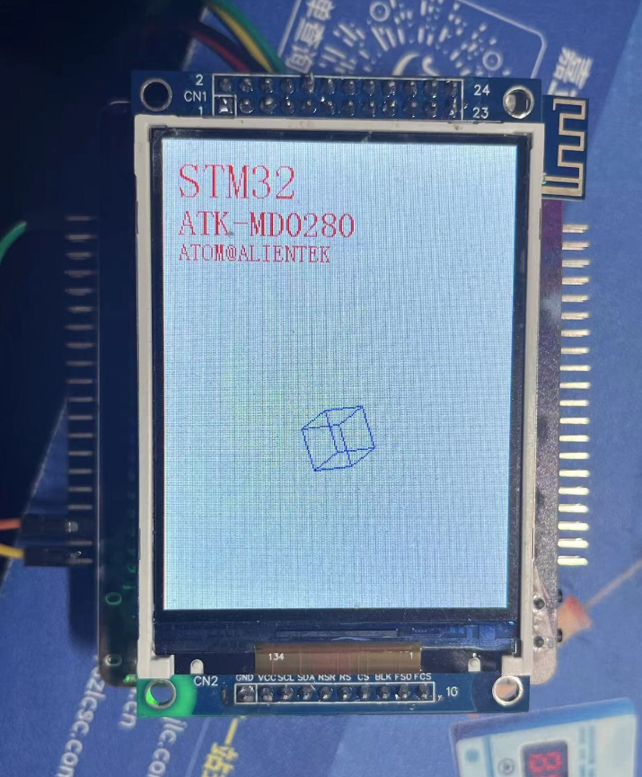
2. LCD
3. WIFI ESP01S
4. EEPROM
5. Bluetooth
6. Buzzer
7. Type-C-CH340N
8.
ADC 9. Buttons
Video Link:
Bilibili Video -- Function Demonstration and
Project Introduction
This expansion board is a learning expansion board based on the GD32F407VET6. It can be used by beginners to learn GD32 and master the use of related peripherals, laying the foundation for building projects. The source code implements the usage of onboard peripheral resources, controlled by macro definitions. Enabling different macro definitions allows you to see the specific phenomena.
The board has a variety of rich resources, including:
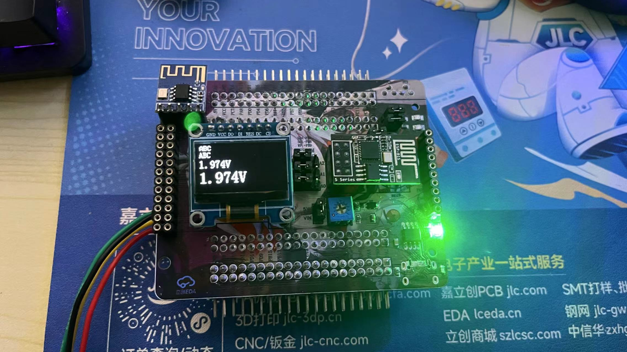
(1) SPI OLED
(2) 2.8-inch LCD
(3) ESP01-S
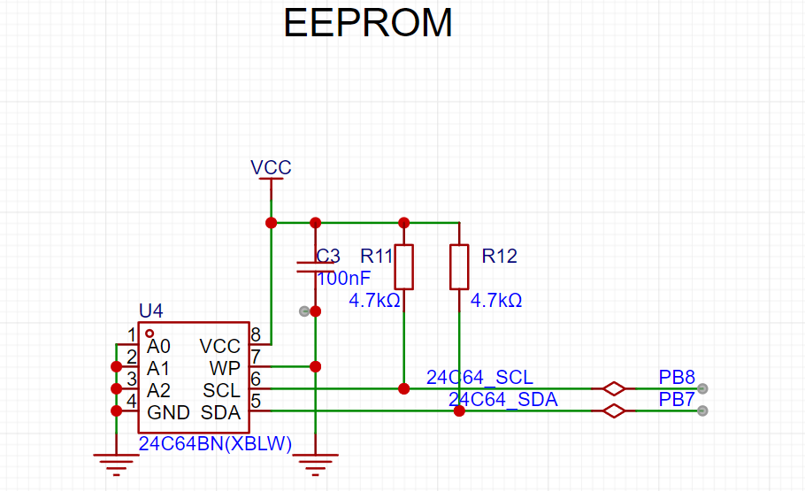
(4) EEPROM 24C64
(5) Bluetooth module
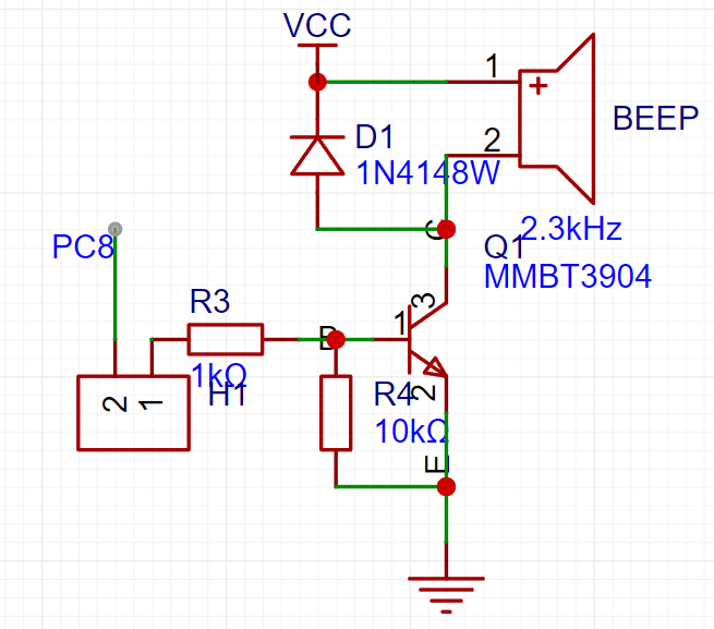
(6) Buzzer
(7) Type-C serial port
(8) ADC potentiometer
(9) Buttons
.
Onboard peripheral module usage:
(1) SPI OLED
software: SPI basic display
(2) 2.8-inch LCD
software: Simulate 8080 LCD display
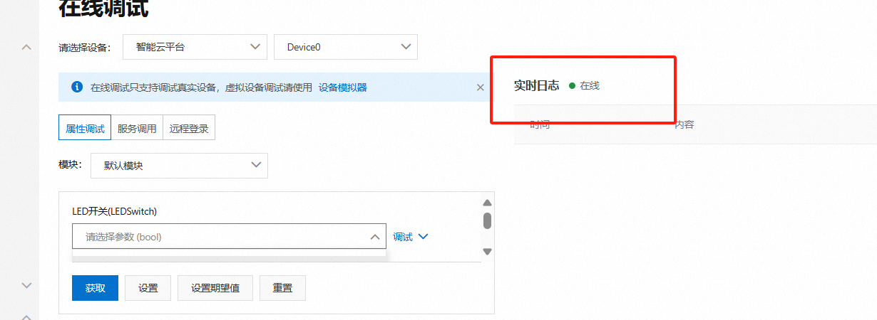
(3) ESP01-S:
AP mode and STA mode .
AP mode: Send data to the microcontroller via mobile phone connection.
STA mode: Connect to Alibaba Cloud, and Alibaba Cloud can issue commands to control the LED
(4) EEPROM 24C64
: Read data
(5) Bluetooth module:
Control LED via Bluetooth.
(6) Buzzer
: The buzzer sounds a prompt.
(7) Type-C Serial Port
: Data can be sent and received with the host computer via a Type-C data cable.
(8) ADC Potentiometer
: The input voltage can be adjusted by adjusting the potentiometer.
(9) Button:
Used to control custom functions.
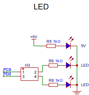
(10) LED Indicator:
Two-way LED indicator
principle analysis (hardware description)
1. Expansion Pin Header:
All pins are brought out through the pin header for easy expansion

. 2. SPI OLED: The
OLED is connected to the hardware SPI pin for easy use of software/hardware SPI driver

. 3.
LCD: CN1 of the LCD is connected to the FMC interface, and CN2 is connected to the SPI. The display can be driven by 8080 or SPI through FMC.

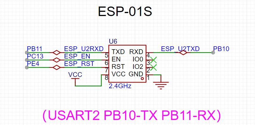
4. ESP01S
Communication Connection: Serial port PB10/PB11.
5. EEPROM:
SCL and SDA are pulled up to VCC for easy use of hardware IIC and configuration of open-drain output.
6. Bluetooth Module :
The Bluetooth module is connected to the serial port.

7. BEEP
Buzzer: Connect the buzzer to PC8 through a jumper cap, or connect it to other pins through a curved jumper cap. PC8 has PWM
. 8. Type-C CH340N
connects to Type-C, allowing direct connection to a computer using a Type-C cable. CH340N is also compatible with the best soldering .

9. Potentiometer:
The potentiometer is connected to 5V via a jumper cap for voltage input measurement.

10. Buttons: The board
has four buttons. Since there is no hardware pull-up, a pull-up input needs to be configured.

11. LEDs:
Two LED indicators are connected to fixed pins via jumper caps, or DuPont wires can be used.
Software code
enables different experiments through macro definitions.
#include "board.h"
#include "demo.h"
AP_PARAMETER ap_parameter={0};
uint8_t test_ret = 0;
uint16_t value = 0;
unsigned char dat1 = 0;
unsigned char dat2 = 0;
float valueVet = 0;
char str[40] = {0};
#define WIFI_AP_TEST 0
#define WIFI_STA_TEST 0
#define ADC_TEST 1
#define EEPROM_TEST 0
#define LCD_TEST 1
#define OLED_TEST 0
int main(void)
{
board_init();
bsp_led_init();
bsp_uart_init();
WIFI_ESP01S_Init();
printf("start
");
#if OLED_TEST
OLED_Init(); //Initialize OLED
OLED_Clear();
#endif /* OLED_TEST */
#if WIFI_AP_TEST
bsp_gpio_on(WIFI_EN);
bsp_gpio_off(WIFI_RST);
delay_ms(100);
bsp_gpio_on(WIFI_RST);
WIFI_MODE_AP_Init();
#endif /* WIFI_AP_TEST */
#if WIFI_STA_TEST
bsp_gpio_on(WIFI_EN);
bsp_gpio_off(WIFI_RST);
delay_ms(100);
bsp_gpio_on(WIFI_RST);
WIFI_MODE_STA_Aliyun_Init();
#endif /* WIFI_STA_TEST */
#if ADC_TEST
bsp_adc_init();
#endif /* ADC_TEST */
#if EEPROM_TEST
i2c_test();//There is a problem
#endif /* EEPROM_TEST */
#if LCD_TEST
/* LCD display */
demo_run(); /* Run the example program */
#endif /* LCD_TEST */
while(1)
{
memset(str,0,sizeof(str)); // Clear the 0 array for later use
value = Get_ADC_Value(CHANNEL_ADC);
printf("value = %d
", value );
valueVet = (value * 3300 >> 12) * (R2 + R1)/R1/1000.0;
sprintf(str, "%.3fV ", valueVet);
printf("voltage = %f V
", valueVet );
OLED_ShowString(0,0,(uint8_t *)"ABC",8,1);//6*8 “ABC”
OLED_ShowString(0,8,(uint8_t *)"ABC",12,1);//6*12 “ABC”
//OLED_ShowString(0,20,(uint8_t *)str,16,1);//8*16 “ABC”
OLED_ShowString(0,36,(uint8_t *)str,24,1);//12*24 “ABC”
OLED_Refresh();
#if WIFI_AP_TEST
//Check if there is a device connected
Get_Device_connection_status();
//delay_ms(500);
bsp_led_toggle(LED1);
//bsp_gpio_toggle(BEEP);
bsp_led_toggle(LED2);
//If the current device is connected to the server (mobile APP is connected to the hotspot)
if( wifi_link_flag == 2 )
{
if( Get_WIFI_AP_Data(&ap_parameter) == 1 )//If data is received
{
//Output the received data
// printf("ID = %d
", ap_parameter.device_id );//Device ID
// printf("data len = %d
", ap_parameter.device_datalen );//Length of the data sent
// printf("data = %s
", ap_parameter.device_data );//Data sent
sprintf(str, "%s", ap_parameter.device_data);
OLED_ShowString(0,20,(uint8_t *)str,16,1);//8*16 “ABC”
memset(str,0,sizeof(str)); // Clear the array to 0 for later use
//delay_ms(500);
}
}
#endif /* WIFI_AP_TEST */
delay_ms(500);
}
}
Notes:
This section can be used to fill in points that require special attention during design and production, or areas prone to errors. Examples:
1. The color silkscreen printing was unclear; this has been corrected in the project
. 2. It is recommended to solder the four fixing pins of the Type-C port on both sides. I accidentally removed mine, damaging the circuit board and causing communication errors. Actual
product images :
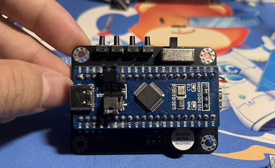
1. Front view of the actual product
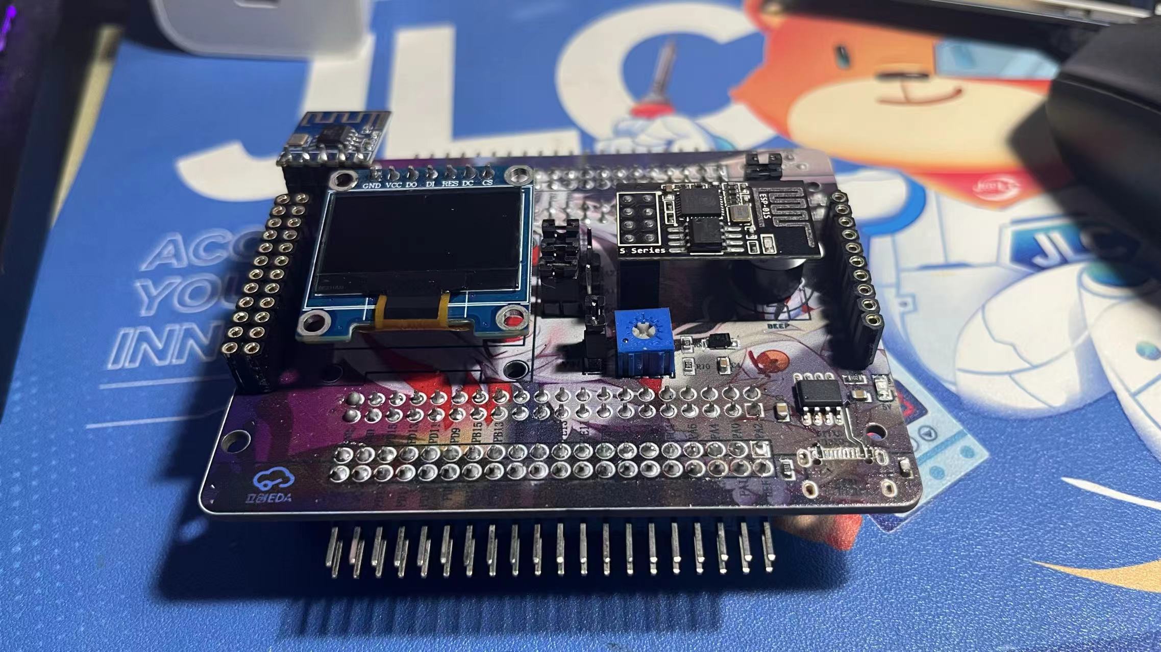
2. Back view of the actual product

3. LCD
4. ADC
5. Type-C serial port output

6. Alibaba Cloud connection
WIFIAP.mp4
ADC.mp4
gd32_TEST.rar
PDF_GD32F407VETE Learning Extension Board.zip
Altium_GD32F407VETE Learning and Extension Board.zip
PADS_GD32F407VETE Learning and Extension Board.zip
BOM_GD32F407VETE Learning and Extension Board.xlsx
91684
Desktop Ornament - Network Clock
This design is a network clock desktop ornament based on the LCSC STM32F103C8T6 development board.
It has four independent buttons, each with the following function: it can adjust the alarm timer, and when the timer reaches the set time, it will sound an alarm.
Video Link:
[Bilibili Video - Function Demonstration and Introduction](【Desktop Ornament - Network Clock - STM32 - ESP01S】 https://www.bilibili.com/video/BV1vpmLYFEbE/?share_source=copy_web&vd_source=9018d111288e591392312c7d0a656c8a)
Project Introduction:
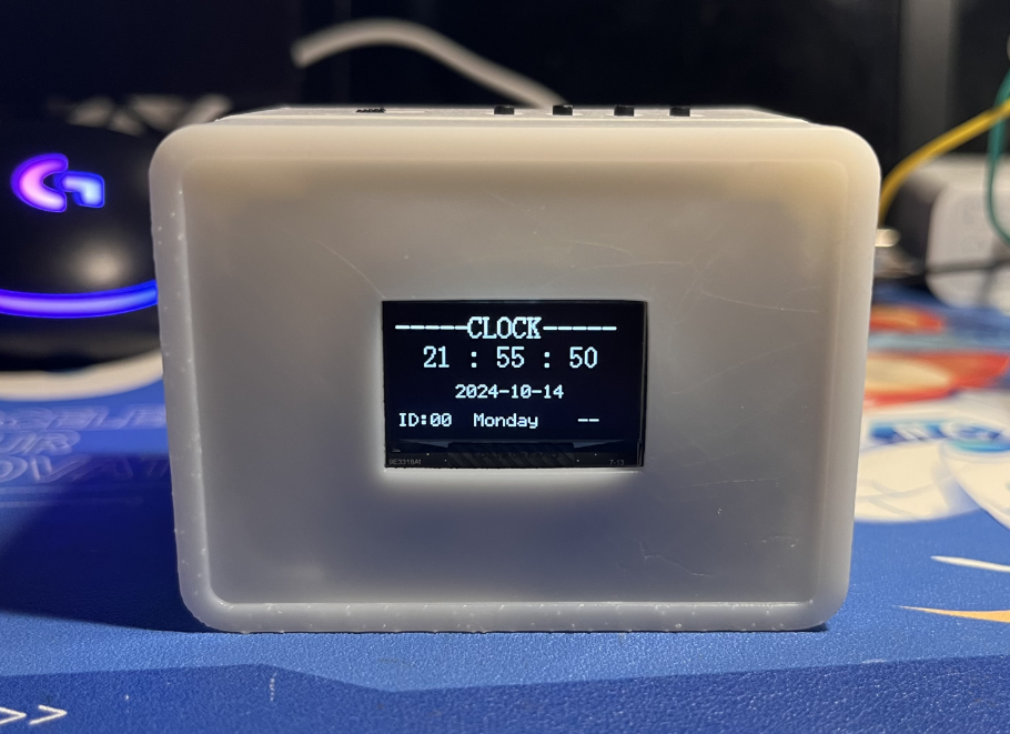
This project is a network clock based on the LCSC development board DiKuoXing STM32F103C8T6, using the RTX real-time operating system. It displays the time on a 4-pin IIC OLED, obtains the time from the network via the EPS01S, is powered by a lithium battery, and charges via a Type-C port. An alarm clock function is included, with the number of alarms controllable via macros and having no upper limit. An alarm is activated via a buzzer.
Project Functionality
This design is based on the network clock of the LCSC development board Dikuoxing STM32F103C8T6;
it has four independent buttons, and the function of each button is defined as follows: it can realize the adjustment of the alarm clock timer, and when the time reaches the set time, it will sound a buzzer to remind.
Clock interface button definition:
K1: View alarm clock 1~N (5)
K2: Turn on/off buzzer
K3: Turn on/off heartbeat light
K4: Undefined
K1K2: Undefined
K1K4: Restart
K3K4: Switch alarm clock interface
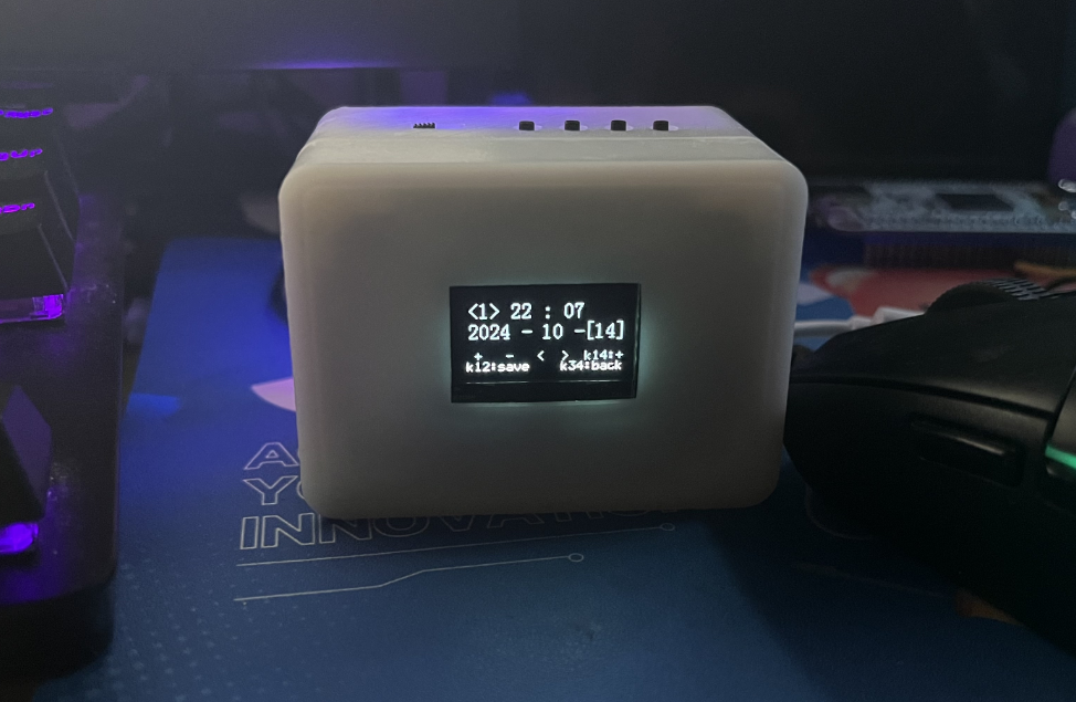
Alarm clock interface button definition:
K1: Add
K2: Subtract
K3: Move left to select
K4: Move right to select
K1K2: Save alarm clock
K1K4: Switch saved alarm clock
K3K4: Switch clock interface
Project Parameters
This design uses STM32F103C8T6 as the main controller;
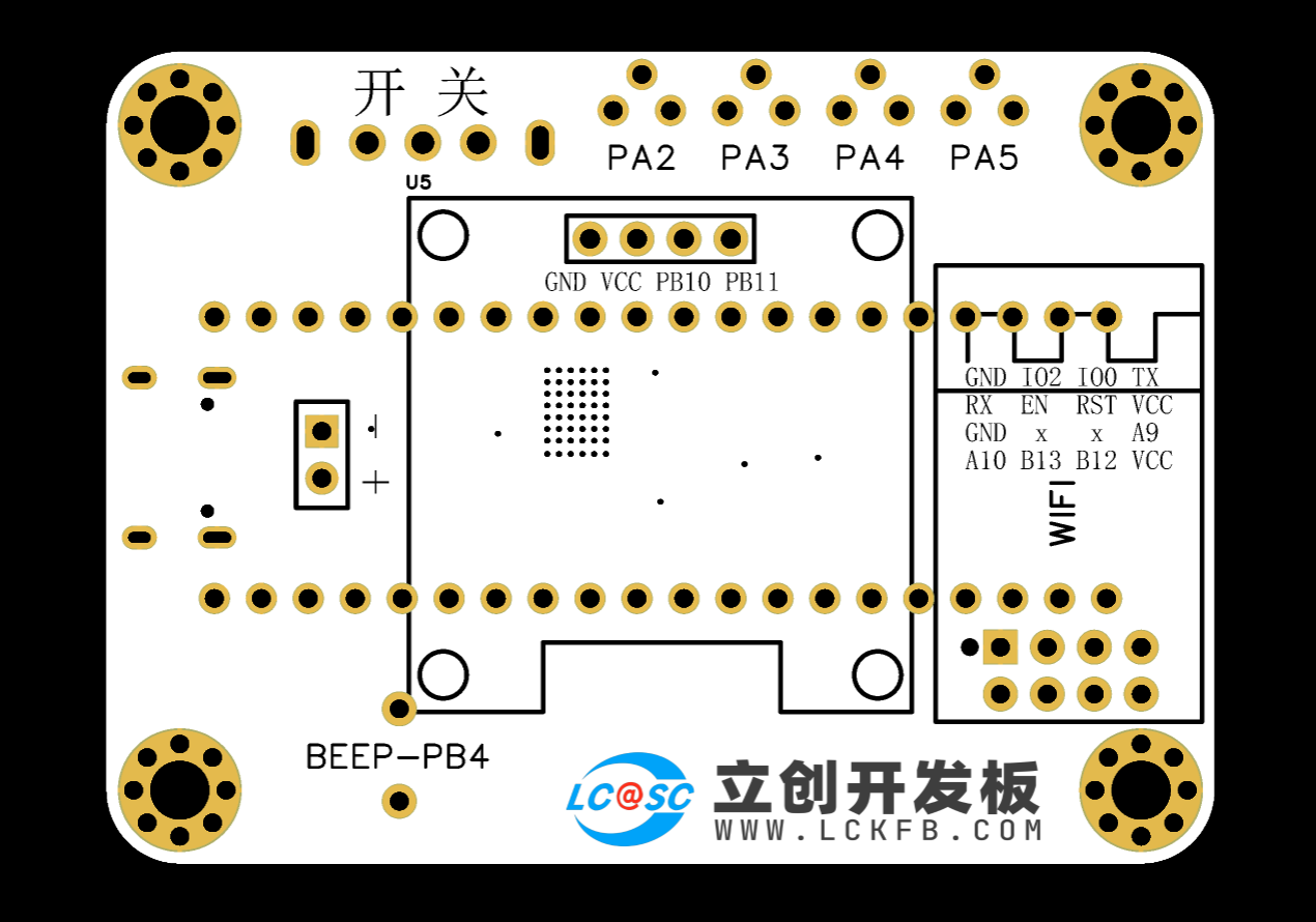
this design uses 4-pin IIC The OLED display shows the current time, date, and day of the week;
a buzzer is used for alarm clock notification;
the wireless module is EPS-01S;
it features four buttons, with various functions achieved through different button combinations;
an onboard LED serves as a heartbeat indicator, which can be turned off by a button.
Hardware Explanation:

Main Control and Power Supply:
Utilizes an STM32F103C8T6 microcontroller with a TYPE-C-16P power

supply. Charging/Discharging Circuit:
Uses a TYPE-C-16P interface as the power supply interface, simultaneously charging the lithium battery. A switch controls whether to use lithium battery power. The circuit automatically switches to lithium battery power when the external power supply is disconnected, ensuring stable power supply.
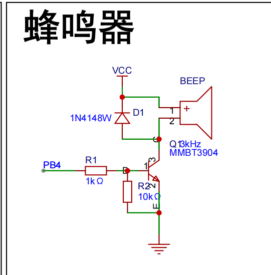
Buzzer Circuit:
The buzzer is controlled by the high and low levels of PB4.
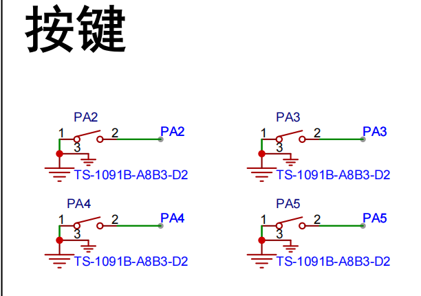
Button circuit:
Configured with four buttons, configured as pull-up input.
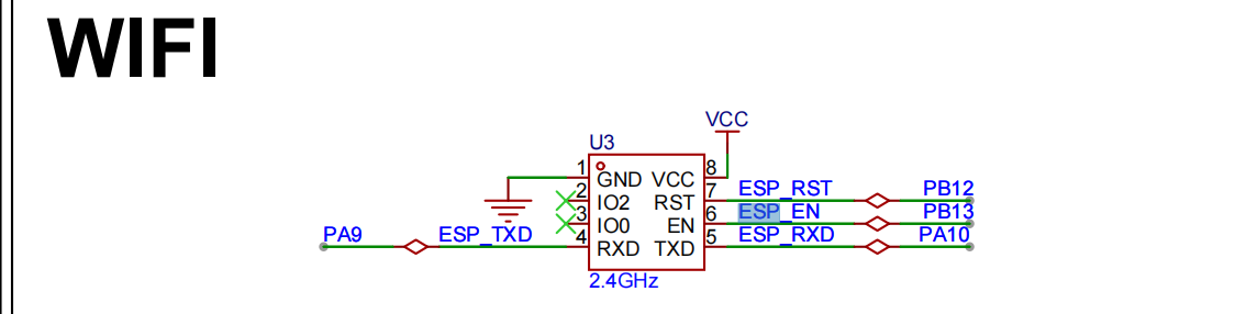
Wireless module circuit:
Connects to serial port 1, PA9, PA10.

Display circuit:
SDA connects to PB11, SCL connects to PB10, using hardware IIC driver
software code
. /**************************** STA mode ****************************/
//In STA mode, the hotspot the WIFI module needs to connect to (you need to modify it to your own parameters)
#define WIFISSID "ChinaNet-nkY6" //Wi-Fi hotspot name
#define WIFIPASS "97spky4v" //Wi-Fi hotspot password
Assembly process:
Flowchart of actual assembly
1. All modules
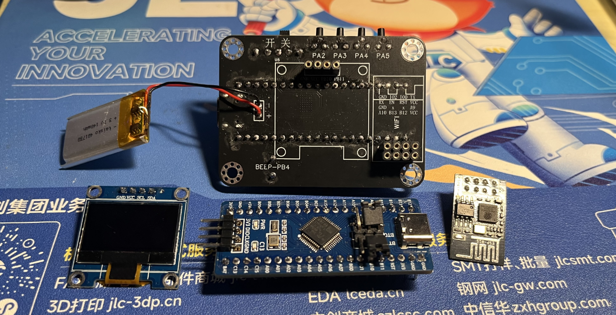
2. Install main controller
3. Packaging and battery protection

4. Install OLED and WIFI module

5. Power on and light up the chip

6. Install into the shell and screw in the screws Actual picture: Complete

actual
picture. For better aesthetics later, a panel can be added, with a pre-reserved groove.

V4-402_RTX_Network Clock.rar
PDF_Desktop Ornaments - Online Clock.zip
Altium Desktop Decor - Network Clock.zip
PADS_Desktop Ornaments - Network Clock.zip
BOM_Desktop Decor - Network Clock.xlsx
91685
electronic


 京公网安备 11010802033920号

 DM74AS2623N


