This schematic design describes
an NFC card with actual circuit functionality. It can be used with other NFC cards such as UID cards to function as public transport cards, Yangcheng Tong cards, Lingnan Tong cards, and access control cards. For details, please search "UID card" on Baidu (UID cards cost an average of 0.2-0.6 yuan each on Taobao). It
can also be used with NXP chips to function as an NFC business card, enabling operations such as scanning to connect to WiFi, add WeChat, and open websites. The chip model is NT3H1101W0FHKH (average price on Taobao: 3-5 RMB/chip).
LED lighting circuitry has been added; the building information is represented by LEDs, which can be soldered on to work with card readers or wireless charging modules, allowing the LEDs representing the building to flash or remain constantly lit.
The PCB design conforms
to the People's Republic of China National Standard GB/T14916-2006 (ISO 7813) "Identification Cards - Physical Characteristics," specifying an integrated circuit card size of 85.60 × 53.98 mm (3.370 × 2.125 inches). Its aspect ratio is close to the golden ratio (1.618:1), and the corner radius is 3.18 mm. Therefore, this card can easily fit in a wallet, similar in size to a bank card or public transport card. It is recommended to choose a 0.8mm thickness (close to the ISO bank card standard of 0.76mm) for the PCB design
, along with standard M3 holes for easy use as a keychain.
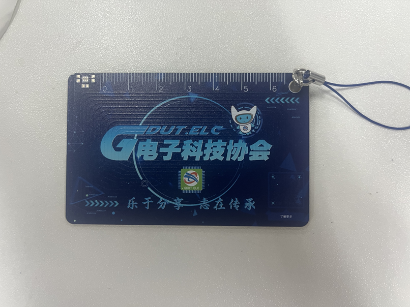
The silkscreen and wiring on the front are designed according to the map of Guangdong University of Technology's University Town campus, and can be used with LEDs to illuminate the buildings when a card is swiped. The back features a 6cm ruler and decorative silkscreen printing. The overall design balances practicality and aesthetics.
Software instructions:
Any NFC function involves programming. There are two types of NFC: business card cards and function cards (see the notes below for details). Without programming, the phone can only read the card but cannot perform any operations (actually, it's more accurate to call it rewriting chip information, but for ease of understanding, we'll refer to it as programming). This is a design issue related to the NFC principle. Therefore, after soldering, you can test the circuit by touching it with an NFC-enabled phone (make sure to turn off the phone's Do Not Disturb function in the NFC settings). If the NFC is recognized, the circuit is successful.
The business card function can be done with a regular Android phone with NFC. The installation package is in the attachment; it's the .apk compressed file. You can directly use this mobile app to write the NFC card information onto the pre-soldered circuit board. The operation is very simple: after downloading and opening the app, you should understand how to use it. Just edit the information, place the card against the phone, and the writing process is complete.
For functional cards, a writer is required, or you can cut the physical card and remove the chip for soldering. Blank UID cards can be used with PN532 to write programs. Specific methods are widely available online; a quick search will yield results.
Physical demonstration
photos of the 2024v2
(due to the use of color silkscreen printing, the board thickness could not be 0.8mm, and was 1.6mm)
and photos of the v1
(due to manufacturing defects at the time, the silkscreen printing on the board used for the photos has slight flaws)
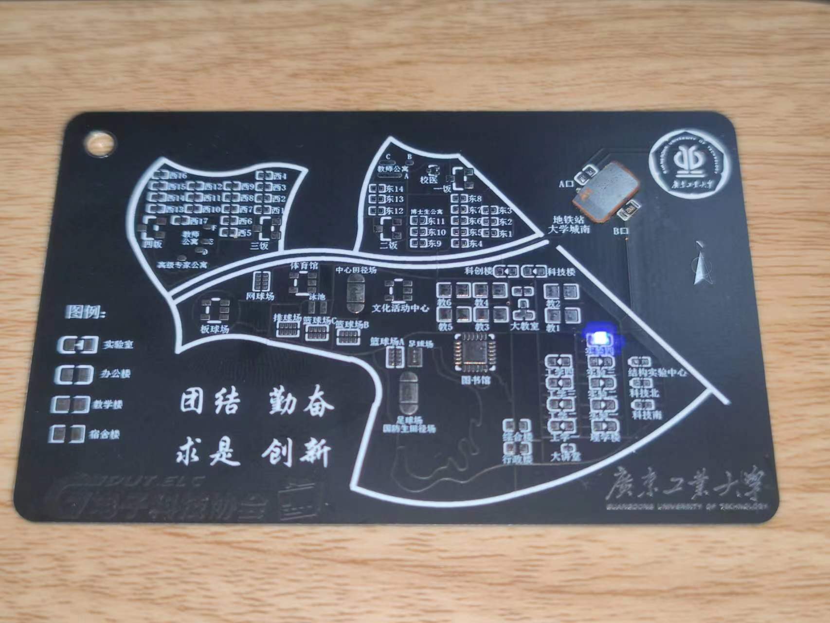
are provided. For v1 board fabrication, a 0.8mm board thickness is recommended. Add customer-defined characters at the designated location (the location is in the Doraemon business card and does not affect the appearance).
Notes on
LED function: When soldering, solder the LEDs to the functional buildings advertised. For example, if the Guangdong University of Technology Electrical Engineering Association headquarters is in Experiment 4, solder to Experiment 4. Do not solder elsewhere. It is recommended to solder only one LED. In the actual circuit, LEDs are connected in parallel, so multiple LEDs can be soldered. The soldering direction is irrelevant. When there are two or more LEDs, one can be soldered in the forward direction and the other in the reverse direction to achieve alternating LED blinking. Only the Experiment Building, Engineering Building, College Building, and Science and Technology Innovation Building have this LED illumination function. When using LEDs, in addition to soldering LEDs for the corresponding building, you also need to solder current-limiting resistors R1 and R3. The resistance value affects the LED brightness; a 4.7KΩ resistor is recommended. You can adjust the resistance value to adjust the LED brightness according to the actual situation. Normally, the LED blinks with the power supply frequency.
However, when soldering U2, the LED also has a constant-on mode. In this mode, solder R2 and R4 with the same resistance values as R1 and
R3 above. The LED is soldered according to its orientation; be sure to solder it in the correct orientation according to the silkscreen markings. (Note that R1 and R3 cannot be soldered in this mode; R2, R4, and U2 must be soldered). Note: R1 and R3 are one group, and R2 and R4 are another group. Only one group can be soldered! The other group should not be soldered! That is, when soldering R1 and R3, R2 and R4 must be unsoldered and not soldered!
NFC function: When using an NFC card (UID card), only solder U1, soldering a blank UID card, a cut-off card, or other types of functional card chips. Do not solder anything else. When using the NFC business card function, only solder C2 and U2. Solder NT3H1101W0FHKH to U2, and solder a small capacitor to C2. Do not solder anything else.
Before using the NFC function, learn to distinguish between different cards! For cards like Yangcheng Tong, Lingnan Tong, campus cards, transportation cards, and access cards, you generally need to solder a UID card (or cut a chip from a physical card and solder it on). The business card function allows your phone to scan and read information, such as connecting to Wi-Fi, opening a website, or adding WeChat friends. It's an operation command; use your imagination to figure out how to use it. Pay attention to the differences between the two functions.
If you are cutting a card to solder, be careful not to damage your original campus card or transportation card. Don't blame me if you have to replace it! Common cards on the market include UID cards, M1 cards, CUID cards, IC cards, FUID cards, etc. They have different characteristics, and some even have different operating frequencies. I have only tested UID cards and found them to work. Before using the relevant functions, it's recommended to first learn about the differences between UID, IC, and ID cards on Baidu to determine which type of card you have. Not all cards can be emulated; encrypted cards cannot be emulated, and even those small, round, blue key-shaped cards may not be emulated. Learn the relevant knowledge first.
The NFC and LED functions are independent and can be used separately or together. However, to make the LED constantly lit instead of flashing, R2 and U2 must be soldered first, and R1 must not be soldered .
A known bug exists:
the NFC coil winding on the PCB has a problem, resulting in a poor resonant frequency. Currently, UID cards are usable, but the effect is mediocre and needs improvement. This is mainly because the author is not very familiar with RF simulation and doesn't know how to draw an NFC coil; they can only guarantee it works, not that it's correct, haha. They will try to improve it next year.


 京公网安备 11010802033920号

 STK401-100


