This 7-channel infrared transistor sensor is designed for club training, guiding students to understand common steps in electronic design, learn about voltage comparators and transistors, master the ability to design and build electronic devices using EDA, develop the ability to independently research and analyze circuits, and learn about the design and fabrication of 4-layer circuit boards.
Circuit schematic: (Only a small portion is shown for explanation; the rest can be found on the schematic page.)
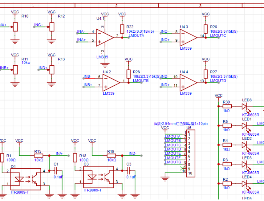
Selection introduction: The LM339 is a single-channel IC containing four independent voltage comparators. It is less sensitive than the LM324 and can directly output VDD or VSS, making it better suited for digital logic gates, logic switches, and other fields. It also eliminates the need to consider the characteristics of operational amplifiers, making it suitable for introductory learning of voltage comparator applications using operational amplifiers. The simple circuit principle allows for the creation of suitable modules for preparation for an in-school interest-based intelligent car competition, aligning with motivating learning methods and a normal growth path.
ITR9909: An infrared phototransistor pair, consisting of an infrared emitting diode (LED) and an infrared receiving diode (NPN phototransistor). Its principle is relatively simple and can guide learning about analog-to-digital conversion concepts and the detection principle of optical sensors.
Circuit principle:
Regarding comparator A:
The ITR9909 is an infrared phototransistor pair. The left side emits infrared light, and the right side is an NPN phototransistor.
The left infrared emitting diode emits infrared light. If there is black tape on the ground, it will absorb the infrared light, resulting in a low light reception by the transistor. At this time, the NPN phototransistor on the right has a low current, which can basically ensure a high voltage of INA+, close to +3.3V.
An LM339, a four-channel operational amplifier, is used here as a voltage comparator. In the A op-amp section, INA+ is connected to a potentiometer with a total resistance of 10KΩ. Adjusting the positioner can change the reference voltage of INA+, thereby controlling the sensitivity.
After power-on, the ITR9909 continuously emits infrared light. Under normal control conditions, the infrared phototransistors will be on both sides of the black line. There is no black tape on the ground, so part of the emitted infrared light can be received by the NPN phototransistor. At this point, the NPN phototransistor can handle a large current, pulling the INA+ voltage low. The voltage comparator in the LM339 compares the voltage and determines that because INA-, OUTA outputs a high level, resulting in a high-level GND signal for the pin header. Simultaneously, the voltage difference across the LED is insufficient to light the surface-mount LED, meaning the LED is off under the default state (with light reception).
If the ITR9909 comes into contact with black tape, the emitted infrared light cannot be effectively reflected to the phototransistor, resulting in a smaller current flow. In this case, INA- will have a larger voltage. The comparator finds that INA- is greater than INA+ (the voltage across INA+ can be adjusted using a potentiometer; during sensitivity adjustment, the voltage of INA+ is kept below 3.3V). At this point, a low-level signal is output, and the pin header outputs a low-level VCC signal. Simultaneously, the voltage difference across the LED is large, lighting the surface-mount LED, and the port outputs a low level.
This process achieves line-following detection, visual communication to the user, and I/O output to the interface.
Experimental phenomena: (Here, 32 is only powered by 3V3)
After soldering the finished product and adjusting the potentiometer appropriately, if the tube can receive reflected light (i.e., the non-black line area), the corresponding channel LED will not light up, and the corresponding pin header interface will output a high level (with the Vcc port connected at 3.3V, the measured voltage difference between the signal port and GND is approximately 3.1V).
If the reflected light cannot be received (black line area), the corresponding channel LED will light up, and the pin header interface will output a low level.
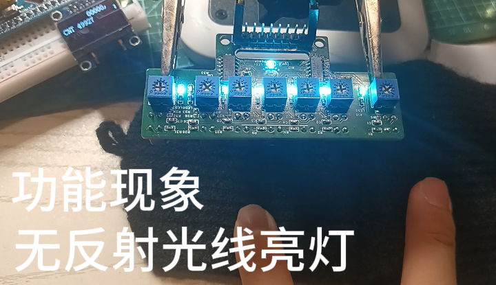
1: Ineffective reflection, LED lights up;
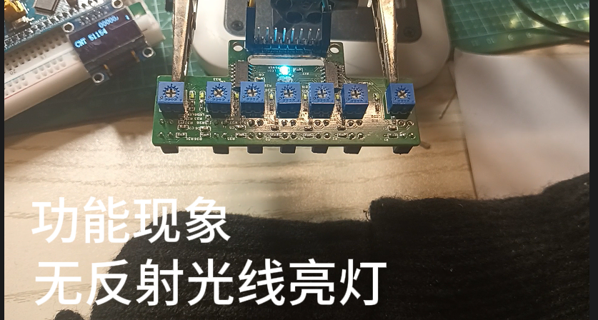
effective reflection, LED turns off.
Debugging steps:

Adjusting the potentiometer multiple times can achieve a precise response to the port voltage corresponding to the threshold reflected light intensity.
Cost Report:
Default channel is Taobao; other channels will be specified separately. Organized in groups of 8:
10K potentiometer: 3.36/5 pieces, free shipping;
1TR9909 infrared transistor pair: 0.64/each, 1 yuan shipping;
10KΩ resistor: 0.8/50 pieces, 2 yuan shipping; 100Ω resistor:
same as above;
1KΩ resistor: same as above;
0.1uF capacitor: 2/200 pieces, 2 yuan shipping;
0603 LED: 20/0.5 yuan, 2 yuan shipping;
LM339 voltage comparator (original): 0.78/each, 0.5 yuan shipping.
1*10 Pin 254 female connector: 1.98/10 rows
including shipping. Calculated for a group of 8 people, with each person having one piece, the flat cost = {12*3.36+0.64*56+(1.6+2)+(1.6+2)+(1.6+2)+(2+2)+(3*0.5+2)+(0.78*16+0.5)+1.98}=109.42/8=13.7 yuan, which is within the reasonable expenditure range for students' interest-based learning.
Reference documents: Everlight ITR9909 Technical Manual, LM339 Technical Manual, LM324 Technical Manual.
Existing sensor configuration designs available online.
A step-by-step guide to building a grayscale sensor from scratch (complete) - Bilibili - Directions and ideas provided by Rongyang Electronics.
LM339 Working Principle + LM339 Function + LM339 Pin Diagram and Function Description, helping you understand LM339 - Zhihu (zhihu.com).
LM339 Chip Working Principle and Pin Diagram Reference - LM339 Pin Diagram and Function - CSDN Blog.
Welcome to exchange and discuss in the comments section. My technical skills are not very strong, and I may have problems in circuit analysis, component selection, PCB layout, etc. I hope you will kindly offer your guidance.


 京公网安备 11010802033920号

 1SMB5341B


