This project is a dedicated DC-DC controller designed specifically for boost switching power supplies.
Input Voltage 12V, Output Voltage 24V, Output Current 5A, Maximum Supported Output 180W, Automatic Overcurrent Protection, Overtemperature Protection, and Built-in Soft Start.
: 1. This circuit adds a totem-pole circuit to increase the driving capability of the MOSFET.
2. This module integrates a TX4221 chip
. 3. The output voltage is adjustable, as shown in the formula below.
4. The input current-limiting resistor value is adjustable, as shown in the formula below.
5. The switching frequency is adjustable, as shown in the formula below.
The FT232USB to serial port module can be used for programming and debugging.
It can be used for communication between host and slave computers (this chip can convert RS232 and EEPROM). This project only developed the most basic functions of this chip.
PADS_FT232USB to serial port module, can be used for programming and debugging.zip
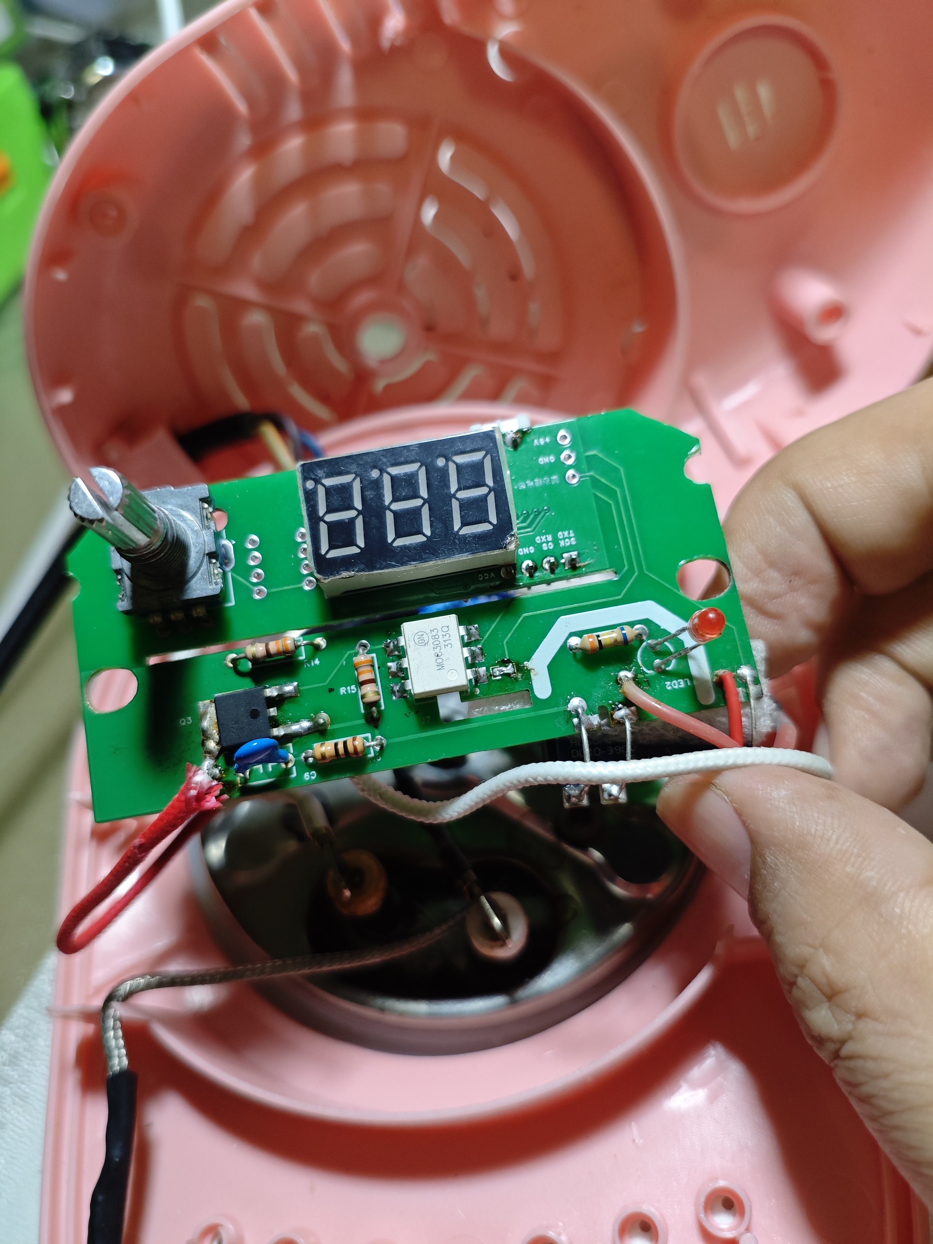
Based on https://oshwhub.com/lilinkai/jian-dan-jia-re-tai, this is a slightly modified version
of a children's cooking toy that they no longer use, with the circuit board replaced.
Instructions for use: (This is the original instruction manual; I've removed the fan hardware, but I don't know how to modify the software. Could someone please help me modify it?)
1. Long press to enter the temperature setting interface, then click the knob once, and then rotate it left or right to adjust the temperature range from 30-250 degrees Celsius! Long press again to exit the setting interface!
2. Double-click to turn on the fan for cooling. Note: Manually turning on the fan will not heat the room!
3. Single-click to wake from sleep mode. Automatic sleep mode lasts approximately 30 minutes! Automatic sleep mode: If no click is made within 30 minutes of operation, it will enter standby mode at 100 degrees Celsius!
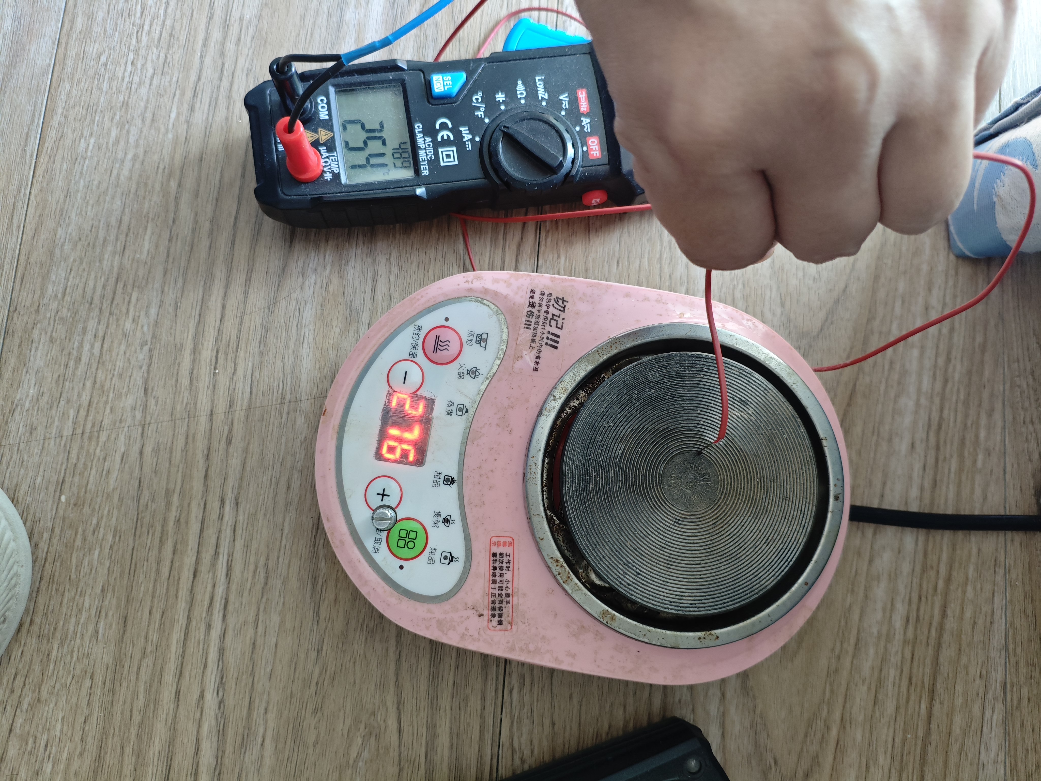
Currently, the program is not entirely satisfactory (I don't know how to modify the program): 1. The maximum temperature can only be set to 255 degrees Celsius, but my small electric stove can probably reach 400 degrees Celsius. 2. The initial surge upon startup is quite strong. I set it to 255 degrees Celsius, but it actually reaches 280 degrees Celsius. It takes quite a while to cool down to 255 degrees Celsius, after which it becomes very stable.

templs.hex
Heating platform PID control program.zip
PDF_Low-cost heating table control board.zip
Altium_Low-Cost Heating Table Control Board.zip
PADS_Low-Cost Heating Table Control Board.zip
BOM_Low-cost heating table control board.xlsx
91763
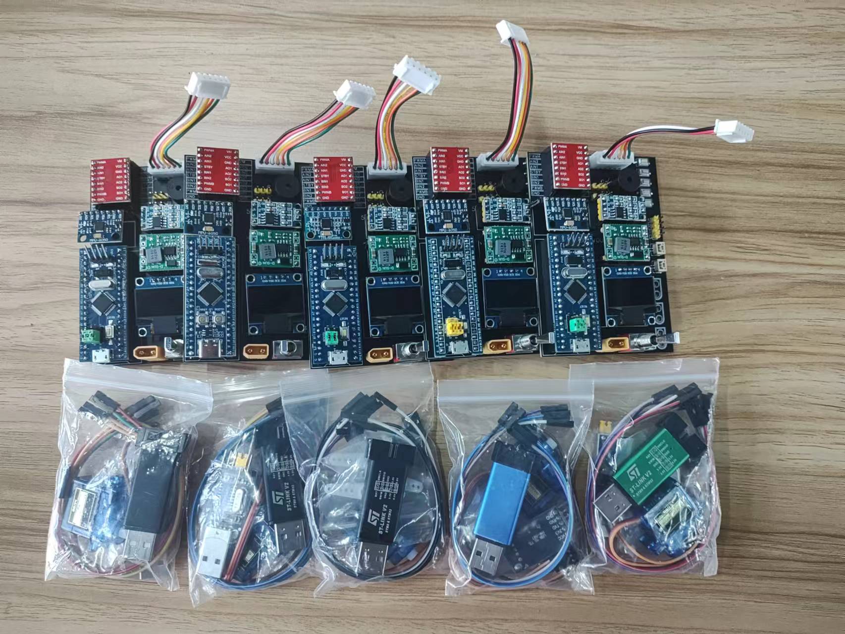
SkyStar LVGL Learning Extension Board
GD32F407/STM32F407 Skystar LCSC Development Board LVGL Verification Board
I. This SkyStar development board expansion board is mainly used for learning and developing LVGL. For the core board, I used two SkyStar core boards: the GD32 version and the STM32 version, and ported LVGL 8.3 to both. The GD32 version uses hardware SPI to drive the screen display and LVGL 8.3, resulting in somewhat choppy display; the STM32 version uses FMSC to drive the screen and LVGL 8.3, resulting in a smoother display.
II. This design includes three boards: the first is a SkyStar GD32 series board; the second is a SkyStar STM32 series board; and the third is a 4.2-inch touchscreen bare screen 40Pfpc adapter board.
III. Because the core board has an onboard TF card slot and FLASH memory, there is no need to worry about future space expansion. It mainly features CH340 serial communication and two user buttons. The board includes a key and two user LEDs, along with an onboard XPT2046 touch circuit, a 40PFPC bare screen interface, a TYPEC power supply, and a 5V to 3.3V converter. The 3.3V output is enhanced, eliminating power supply concerns. It also features expanded power strips, allowing it to be used as a development board.

IV. Function Introduction
1. The expansion board provides screen female connectors and FPC sockets (the STM32 version's FPC socket is unverified; others work normally). The GD32 uses a 3.5-inch ILI9488 resistive touchscreen; purchase link (http://e.tb.cn/h.gr3Gz31EGs8WosG?tk=c4gK3iXWxeo); the STM32 uses a 2.8-inch ILI9341 resistive touchscreen (compatible with Zhengdian Atom 2.8-inch screens); purchase link (...). (http://e.tb.cn/h.gJu9GcuMnMdWKMa?tk=q9MX3iX2QeG) This link provides a cheap screen that can replace the 2.8-inch screen from Zhengdian Atom, offering good value for money. The software primarily follows the STM32 introduction; the GD32 version mainly verifies the stuttering issue when using LVGL to drive the screen via SPI.
2. Use serial port or buttons to calibrate the resistive touch screen position.
Serial port calibration: Connect the board to the computer via a Type-C cable and open the serial communication software (the software will be included in the attachment)
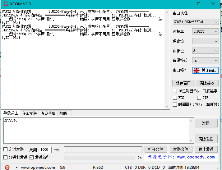
. After powering on, the board will print data to the serial port software to check the hardware status. Normally, the screen model and FLASH model will appear. At this time, send XPT2046 via the serial port software, and the board will enter calibration mode. Follow the prompts to click the calibration

button around the board. Calibration is done by pressing the key silkscreen button on the core board, etc. This can also be done... Calibration
3. To port LVGL 8.3
, the following requirements must be met. The SkyStar development board fully meets these requirements

. First, the development board needs to be able to drive a TFT screen to light up and for the touch function to work properly. At this point, following the instructions in this blog post will allow for a successful port of LVGL 8.3. My
blog post on successfully porting LVGL is available here: https://blog.csdn.net/qq_49053936/article/details/136696700?fromshare=blogdetail&sharetype=blogdetail&sharerId=136696700&sharerefer=PC&sharesource=2301_76769471&sharefrom=from_link
However, the blogger did not demonstrate the five test demos included with the LVGL library. Essentially, it involves porting the .c and .h files from the LVGL folder into the program. For details on the porting method, please refer to the LCSC development board technical documentation, which provides a very detailed
explanation: https://wiki.lckfb.com/zh-hans/tkx/tkx-stm32f407vxt6/module/screen/3-5-ili9488-color-screen.html
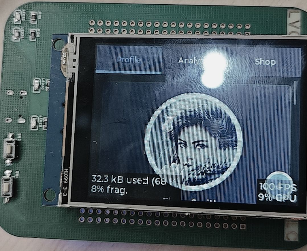
I have already ported the five demo test programs into the program. Simply uncomment the corresponding demo to run it. The demo

programs will be uploaded in a compressed package. The demonstration images are shown below.
4. Video Demonstration:
This section demonstrates the process. For more details, you can experience it yourself. Videos include demonstrations of porting the LVGL8.3 demo to GD32 and STM32 respectively.
5. Bug Fixes:
The issue of PA4 being reused by user buttons, causing the program to malfunction, has been resolved. Thank you for pointing it out.
stm32f407.mp4
gd32f407.mp4
XCOM V2.0.rar
GD32F407LVGL8.3.rar
STM32F407LVGL8.3.rar
PDF_SkyStar LVGL Learning Extension Board.zip
Altium_SkyStar LVGL Learning Extension Board.zip
PADS_SkyStar LVGL Learning Extension Board.zip
BOM_SkyStar LVGL Learning Extension Board.xlsx
91764
MPS Low Cost - FFOC - MP6539GV
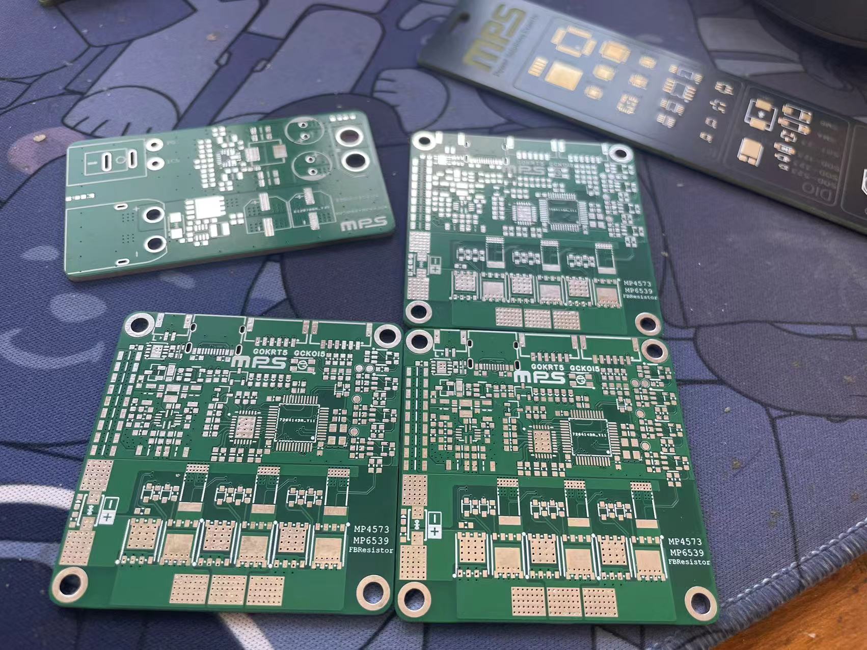
The MPS-MP4573+MP6539GV solution is a brushless motor driver suitable for learning, robot chassis motor driving, robot friction launcher driving, and has a mini size of 50*50mm. It supports SPI encoder input, CAN communication, RC, RM, and smart cars!
MPS Campus Program
Participation Link: MPS Campus Program (Recommended by: Zhao Bin)
Acknowledgements
This driver design wouldn't have been possible without the strong support of MPS, who not only provided the driver and DC ICs but also offered extensive design guidance and Q&A.
Thanks to JLCPCB for the free prototyping and component vouchers for this project. Thank you JLCPCB, support JLCPCB, choose JLCPCB!
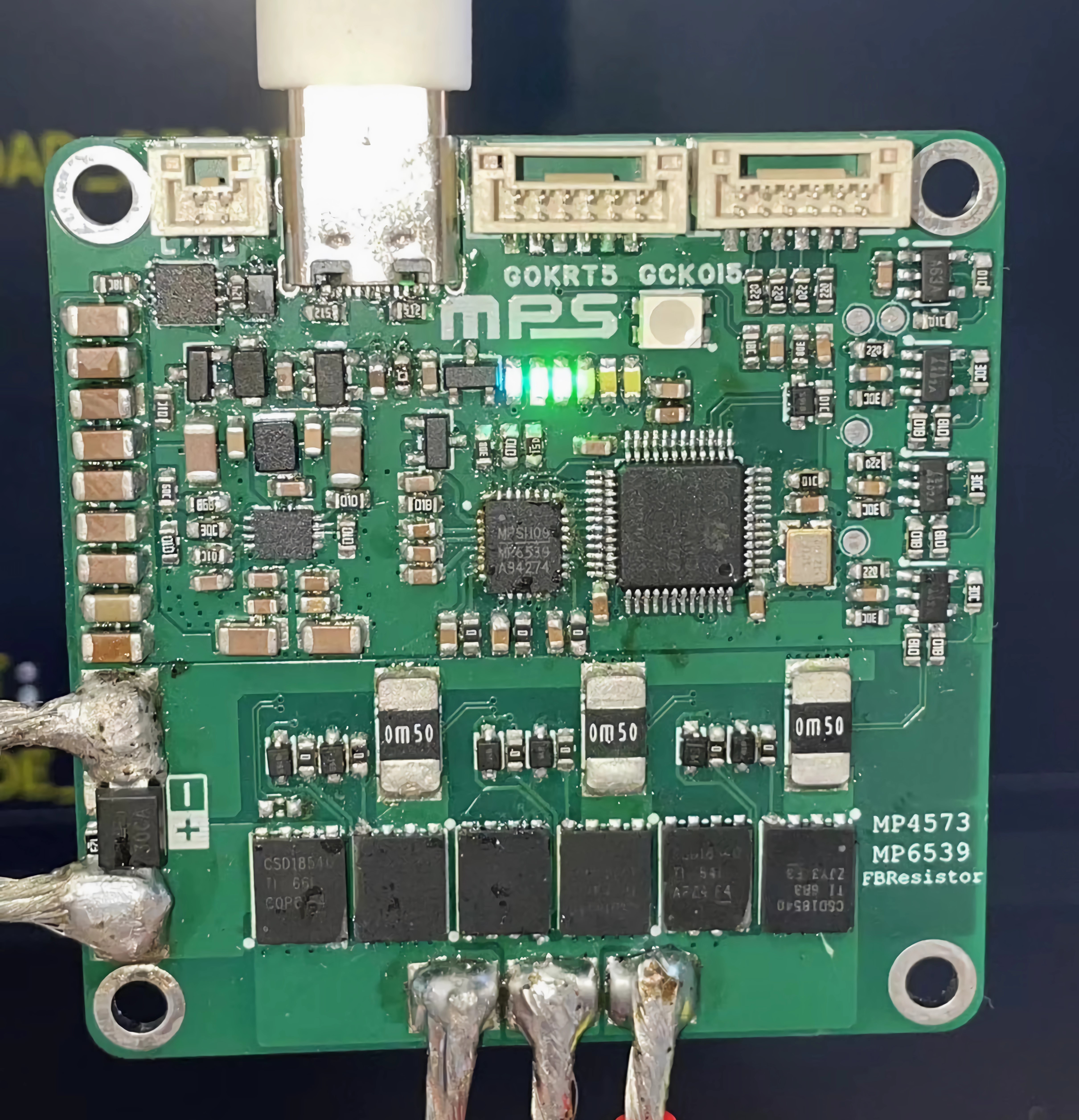
This driver uses MPS chips, including the MP4573 and MP6539GV.
University students can apply for free samples through the MPS Campus Program, including but not limited to the above chips.
If this is helpful to you, please include "Recommended by: Zhao Bin" in your application; your support will be greatly appreciated!
For any questions, assistance, evaluation help, or technical guidance, please contact me. (RC, RM, intelligent vehicles, innovation, any competition)
Personal contact information: z103075

Driver Introduction:
This driver mainly uses STM32G431CXX/STM32G474CXX + MP4573(DC) + MP6539GV (gate driver), and adopts a three-resistor low-side sampling scheme.
Features
: High power output exceeding 1KW (actually measured)
; Mini size (50*50mm); M3 positioning holes at four corners;
USB and DC voltage selectable; strong and weak current switching via PMOS for computer protection;
MP6539GV internal LDO supports driving external NPN for higher drive current selection;
MP6539GV supports error detection (OCP, UVLO), integrated current amplifier, and MOSFET overcurrent protection; Electrical specifications:
Maximum input voltage 60V (DC-limited); Maximum drive voltage 120V (high voltage may require alternative MPS specifications);
Phase current 50A continuous (requires heatsink + active fan cooling);
Recommended operating parameters: 4~6S battery;
Project log
(September 23, 2024); First open-source release
(September 30, 2024); Corrected some component labeling errors in the schematic (R13, R14: 5 milliohms -> 0.5). (milliohms), increased component standardization
(October 11, 2024) Modified the PCB layout of the ADC sampling return path in the sampling section.
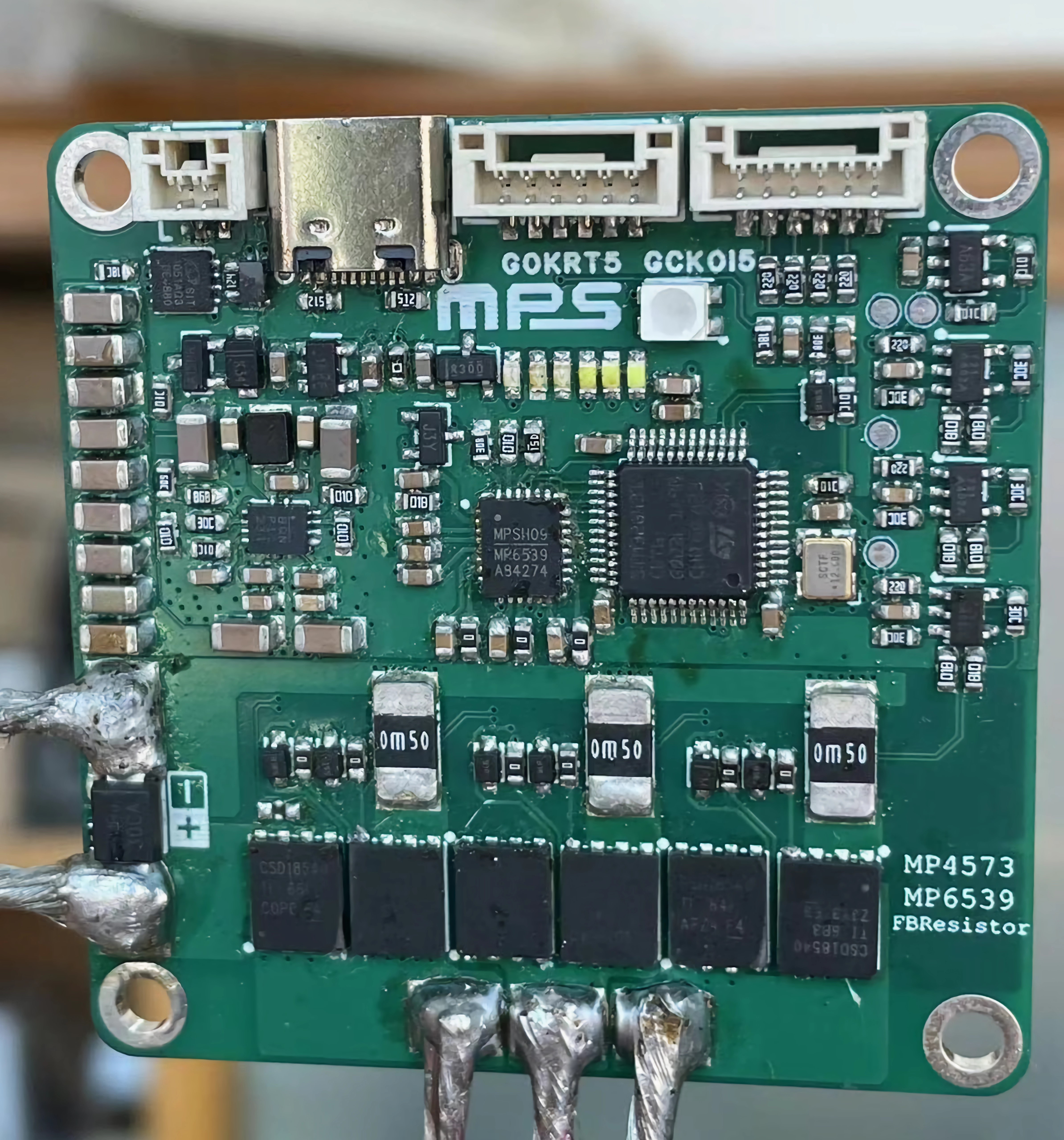
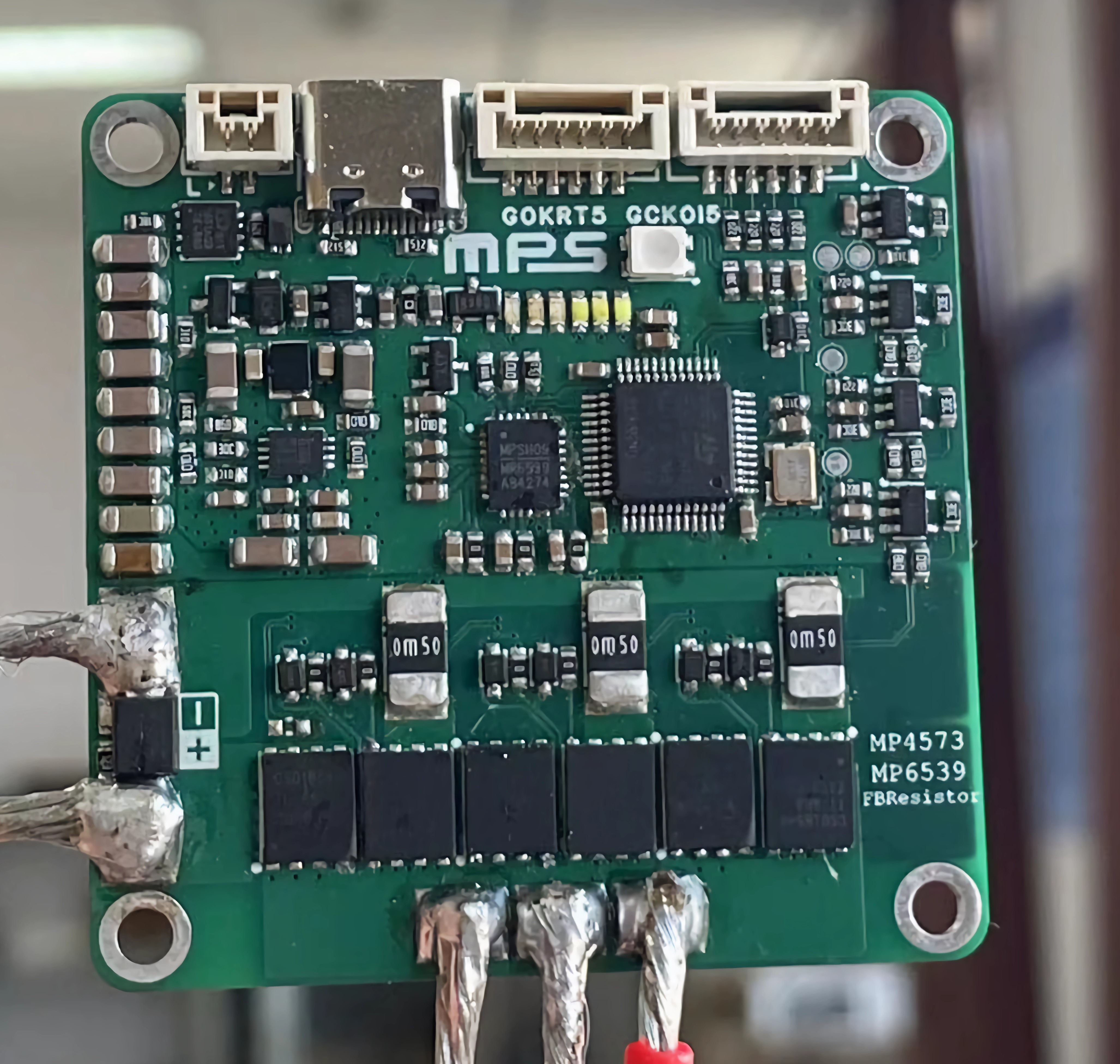
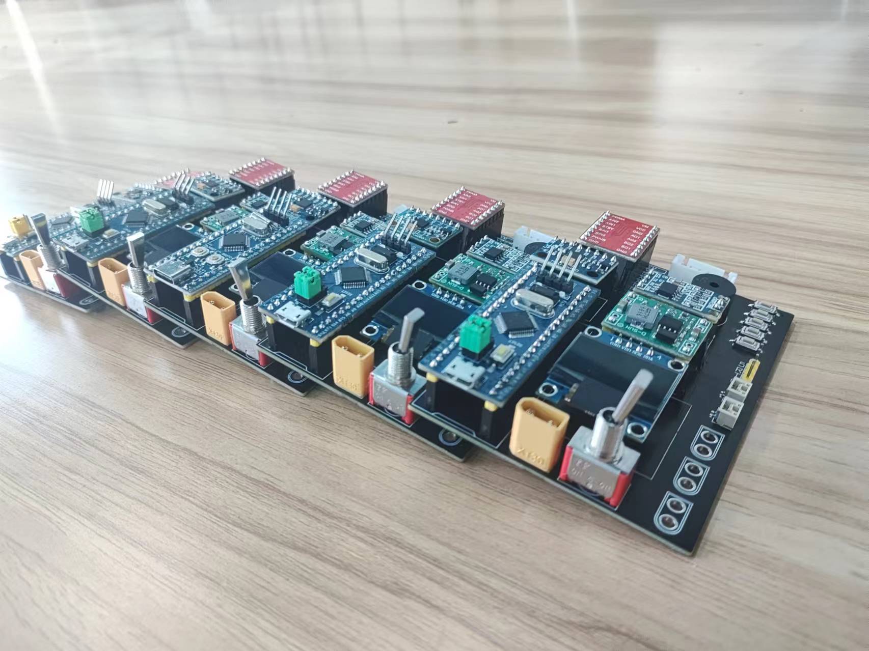
The actual photos
are original, without board cleaning fluid, and quite dirty!
Principle Analysis (Hardware Description)
The hardware principle is clearly explained in the schematic diagram, so it will not be repeated here!
Software Code
The complete code and host computer are still being organized, please look forward to it.
The code I wrote myself is still inadequate and I am ashamed to show it. You can send me a copy of the test code.
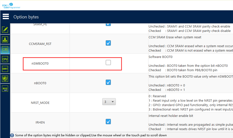
Notes
Since the STM32 G4 series is used, pin PB8 is the CAN pin and also the BOOT0 pin, also known as soft BOOT. Because the CAN function is enabled, it is not pulled down to ground in hardware, so it needs to be pulled down in software. Use STM32CubeProgrammer to pull down, as shown in the figure.
Purchase
three-pin CSD18540
NTMFSC0D9N04CL
PDF_MPS Low Cost-FFOC-MP6539GV.zip
Altium_MPS Low Cost-FFOC-MP6539GV.zip
PADS_MPS Low Cost-FFOC-MP6539GV.zip
BOM_MPS Low Cost-FFOC-MP6539GV.xlsx
91767
electronic
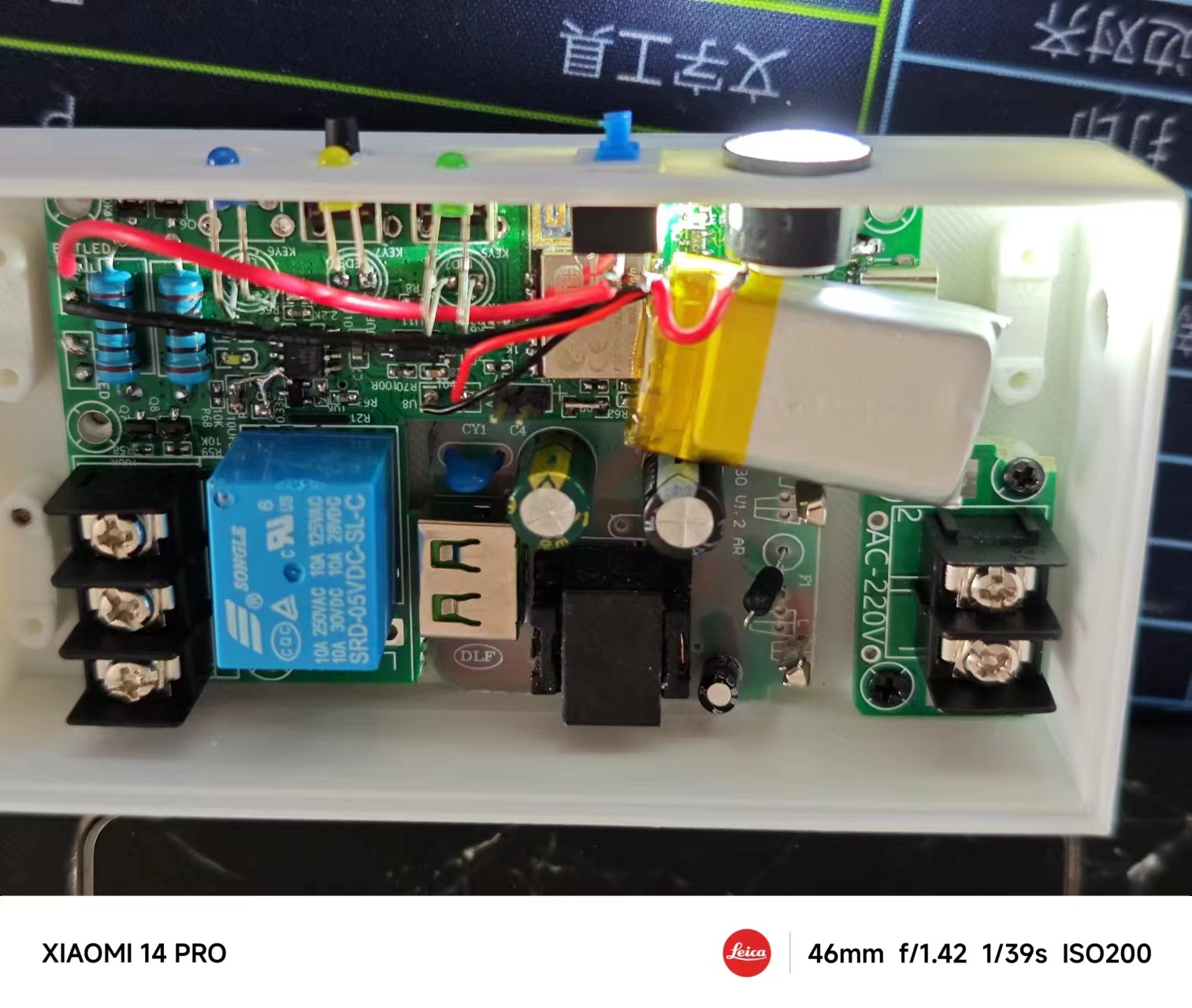
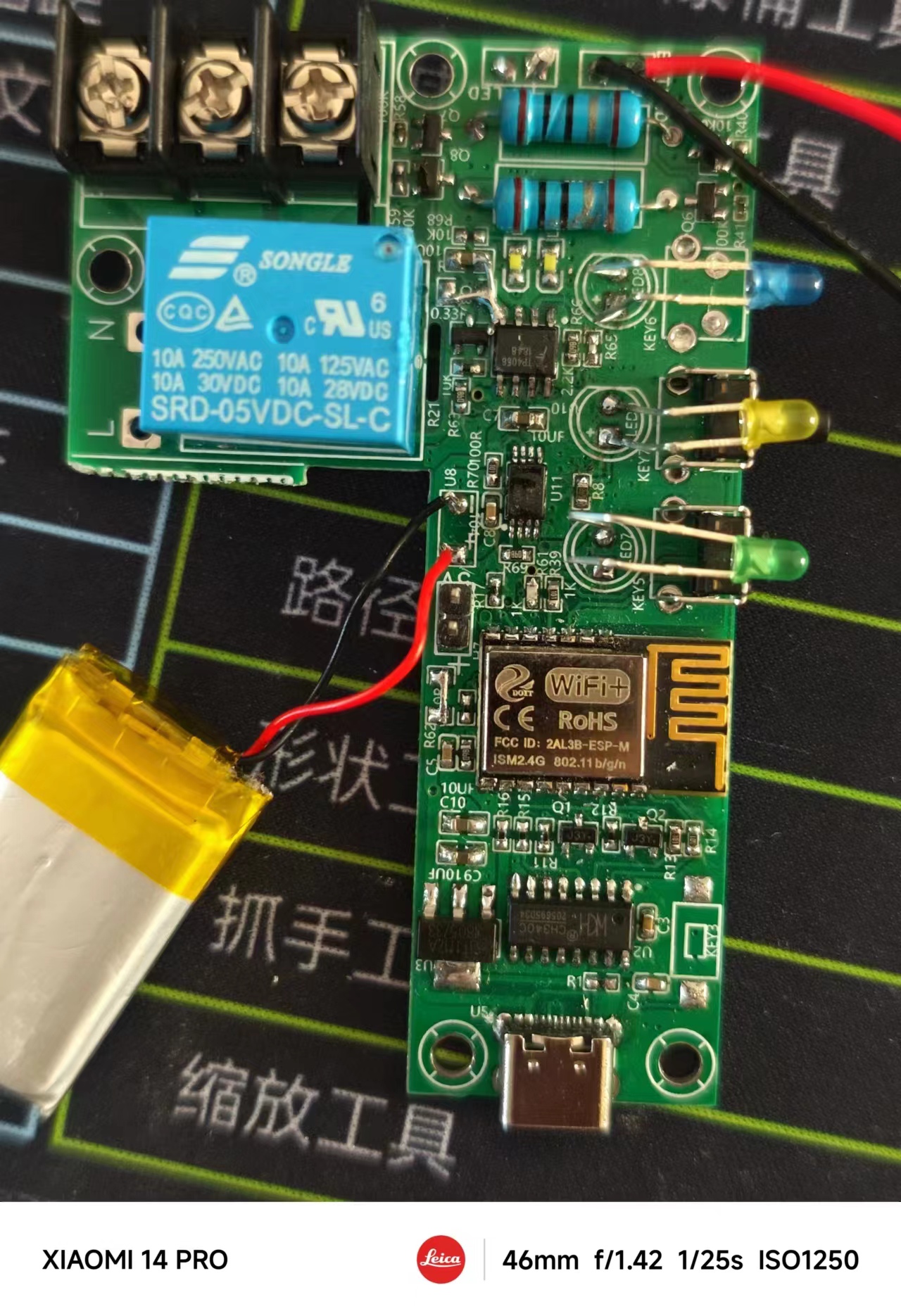


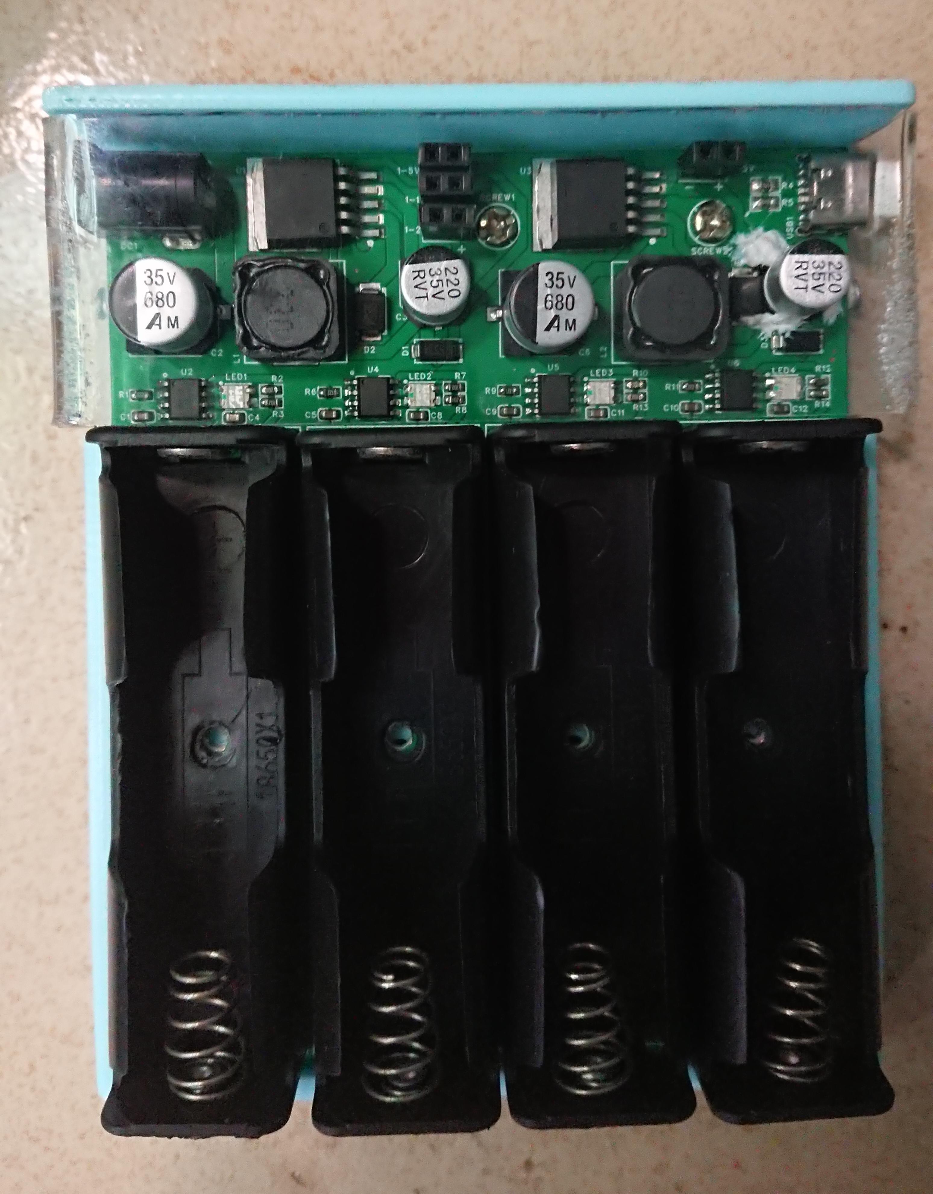
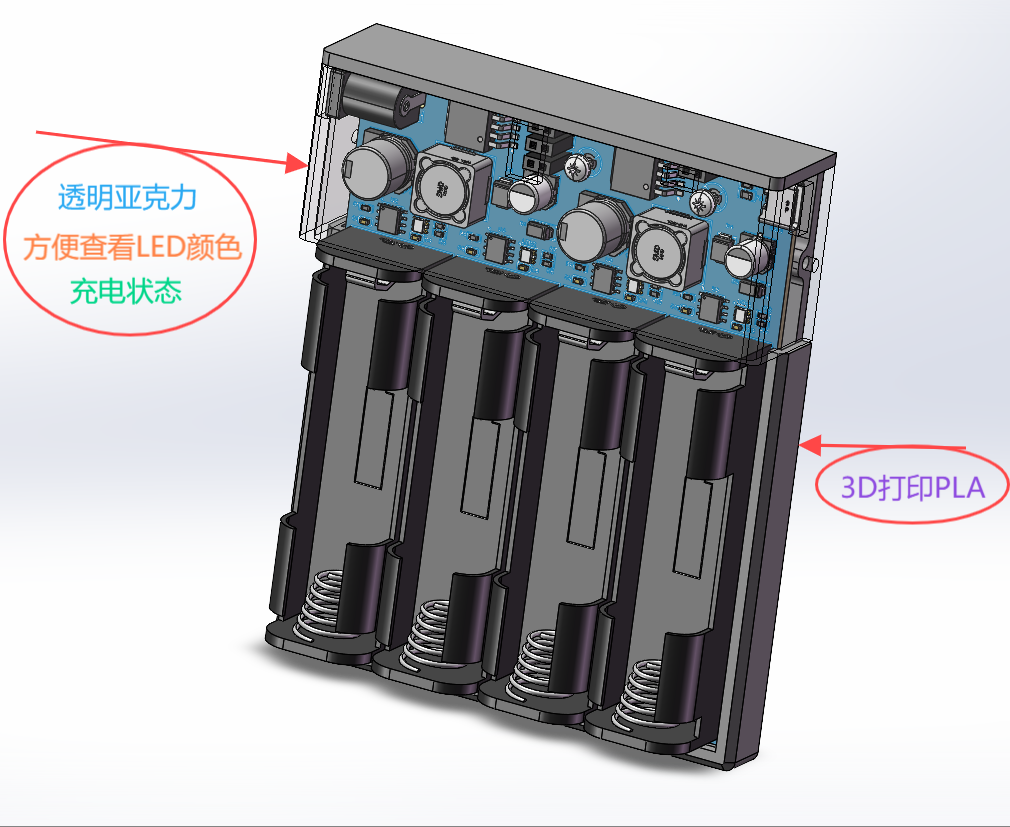 [Image of the actual product:] Because I folded the acrylic by hand, and placed it on the soldering iron at 450°C without experience, it bubbled! The four output ports on the top are not open, making it too difficult to work with without the right tools. Please bear with it. The four screw holes in the battery compartment at the bottom were added later because the JLCPCB 3D model didn't have them. The PCB has been roughly positioned. If there are any discrepancies in the hole placement during the prototyping process, I will provide the STL and SW files for modification. The actual product uses 35V capacitors because that's all I had on hand.


 4. The input current-limiting resistor value is adjustable, as shown in the formula below.
  5. The switching frequency is adjustable, as shown in the formula below.
 This is the datasheet for this chip.
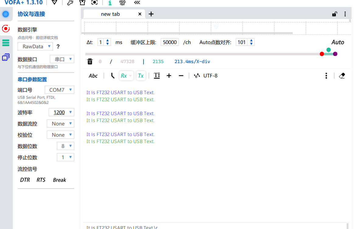


 京公网安备 11010802033920号

 AP1186T515LA


