 : The above power supply circuit can receive 5-12V DC power. A diode is added to prevent reverse connection of the power supply. Afterwards, the input DC power undergoes multiple filtering (high frequency and low frequency) through capacitors. Then, an LDO linear regulator converts the input 5-12V power supply into a stable 5V output, providing the power foundation for the other circuits.
 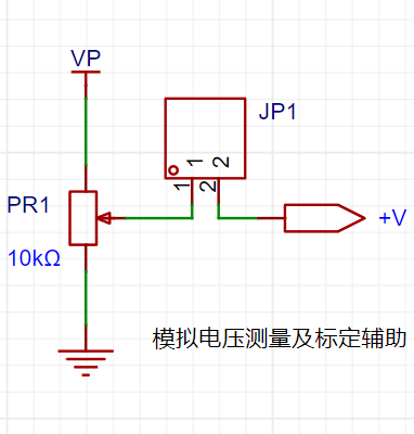 measurement circuit. The voltage measurement circuit
  Current Measurement Circuit
 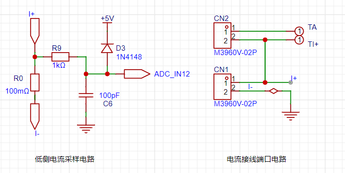 Design Analysis:
 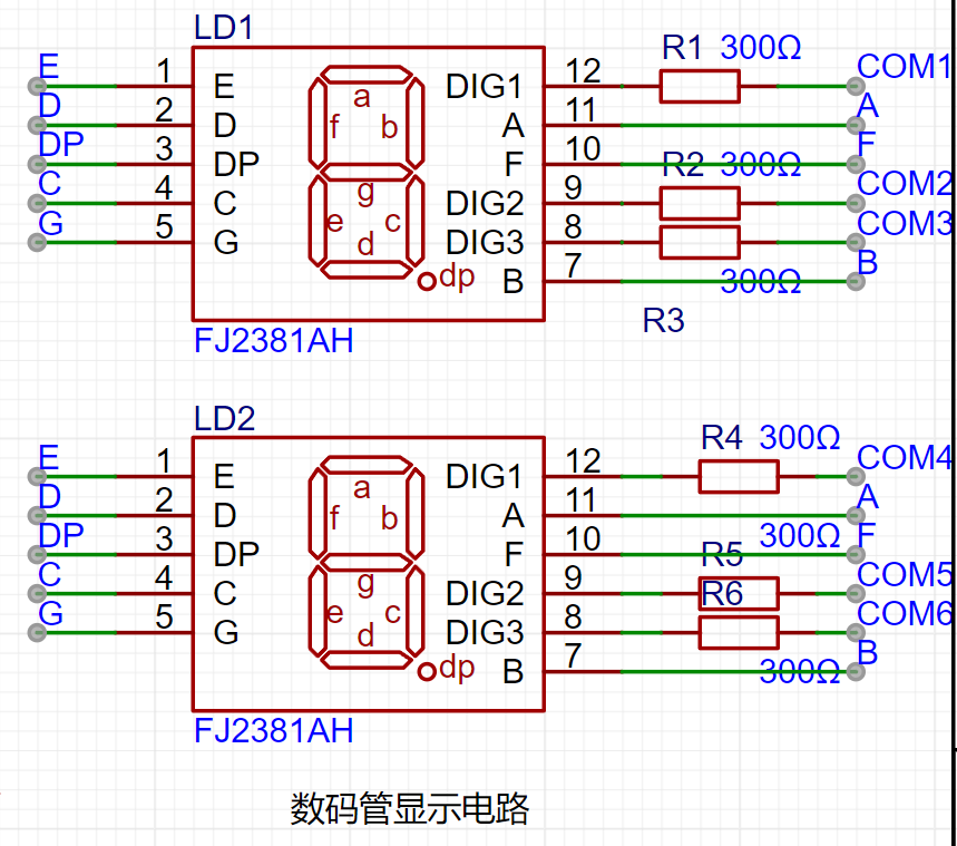 . After reading the ADC data, it is displayed on the digital tube, allowing the user to intuitively see the test results. I accidentally broke a CW32 pad, causing the A segment of the digital tube to malfunction. However, this does not actually affect usage. If a new CW32 is replaced, it will work normally.
All reference designs on this site are sourced from major semiconductor manufacturers or collected online for learning and research. The copyright belongs to the semiconductor manufacturer or the original author. If you believe that the reference design of this site infringes upon your relevant rights and interests, please send us a rights notice. As a neutral platform service provider, we will take measures to delete the relevant content in accordance with relevant laws after receiving the relevant notice from the rights holder. Please send relevant notifications to email: bbs_service@eeworld.com.cn.
It is your responsibility to test the circuit yourself and determine its suitability for you. EEWorld will not be liable for direct, indirect, special, incidental, consequential or punitive damages arising from any cause or anything connected to any reference design used.
Supported by EEWorld Datasheet
EEWorld
subscription
account

EEWorld
service
account

Automotive
development
community

Robot
development
community

About Us Customer Service Contact Information Datasheet Sitemap LatestNews


Room 1530, 15th Floor, Building B,
No.18 Zhongguancun Street,
Haidian District,
Beijing, Postal Code: 100190
China
Telephone: 008610 8235 0740
 京公网安备 11010802033920号

 UPC78L12J


