This open-source circuit adds an audio toggle switch to the EGDETX system PL18 remote control.
The PL18 system's modified open-source address is https://github.com/EdgeTX/edgetx/wiki/Flysky-PL18-%26-PL18EV-Hardware-Mod-for-Complete-EdgeTX-Support.
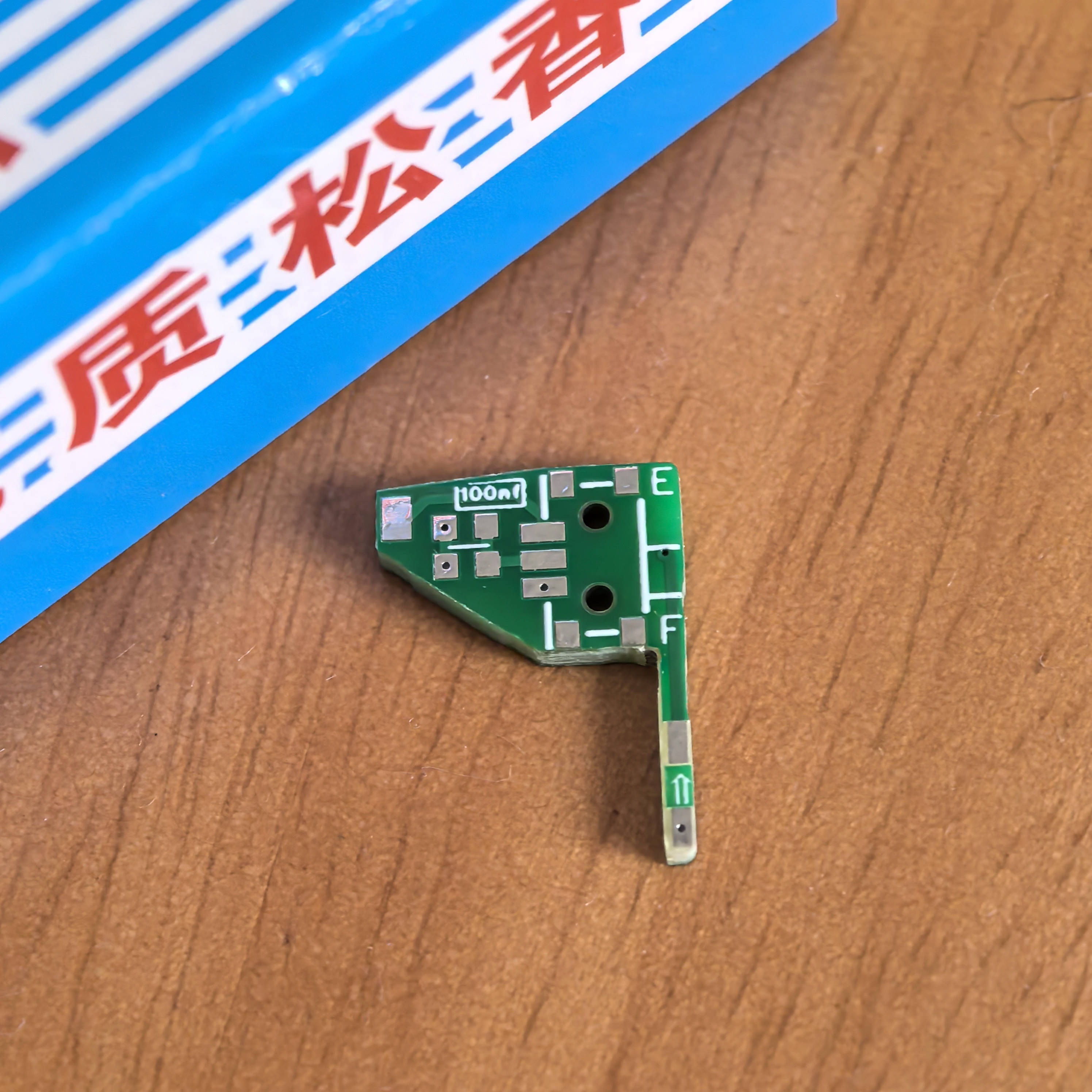
The original project's modification example image is shown below .
. Note: The 100BF capacitor design uses two sets of pads, one for soldering and one as a spare
. The following image shows an example of the flying wire in this project.
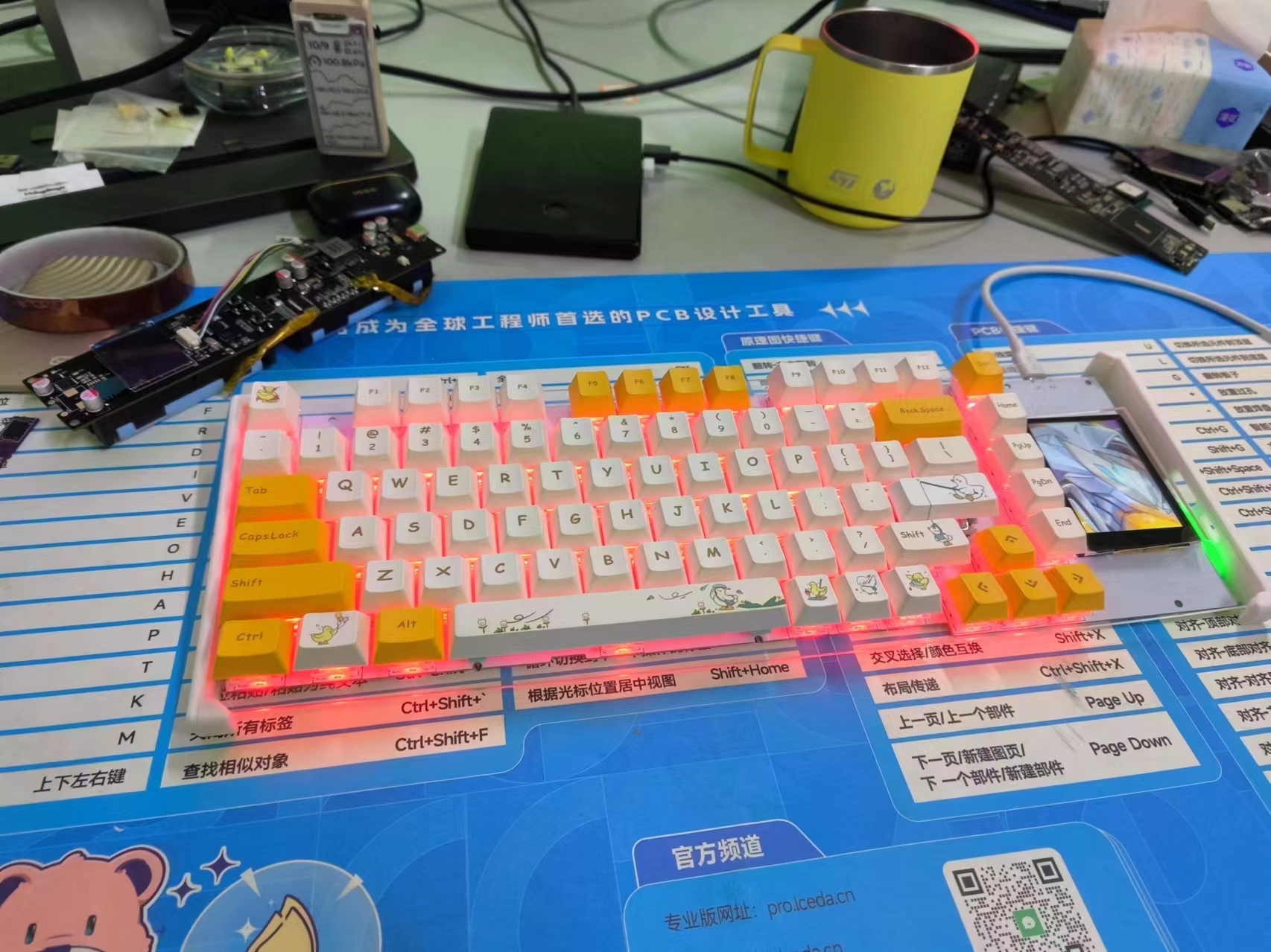
Plus, the OLED screen is both beautiful and fun.
The ESP32S3-based self-balancing scooter project is an integrated project using multiple sensors and PID control algorithms, making it ideal for electronics enthusiasts.
Project Name: ESP32S3 Balance Car Project Objectives: Design and implement a balance car that can automatically maintain its balance. Learn ESP32S3 programming and application. Master PID control algorithms and sensor usage. Project Features: Self-balancing: The car can automatically detect and adjust its posture to maintain balance. Flexibility: By adjusting PID parameters, it can adapt to different environments and ground surfaces. Programmable: Programmed using the ESP32S3, it has powerful processing capabilities and rich peripheral interfaces. Expandability: More sensors and functions can be added as needed, such as Bluetooth control, obstacle detection, etc. Core Components: 1. ESP32S3: As the main controller, responsible for processing sensor data and controlling the motors. 2. MPU6050: Accelerometer and gyroscope, used to detect changes in the car's posture. 3. Motor driver: Such as TB6612, used to control the motor's speed and direction. 4. Motor: N20 DC geared motor with encoder, used to drive the car. 5. Power supply: Lithium battery, providing power to the car. Technical Highlights: 1. Sensor Data Reading: Read data from the MPU6050 via the I2C interface. 2. Motor Control: Control the motor speed and direction via PWM signals. 3. PID Control Algorithm: Achieve balance control of the vehicle. 4. Program Debugging: Debug the program via serial port or Bluetooth to optimize PID parameters. Development Tools: ESP-IDF: Espressif's official development framework for programming the ESP32S3. Arduino IDE: Also used for ESP32S3 programming, with rich library support. Implementation Steps: 1. Hardware Assembly: Solder and assemble the various parts of the vehicle. 2. Software Programming: Write code to implement data reading, motor control, and PID control. 3. Debugging and Optimization: Adjust PID parameters using debugging tools to optimize the vehicle's balance performance. Expected Outcome: An ESP32S3 balancing vehicle that can automatically maintain balance. In-depth understanding of ESP32S3 programming and sensor usage. Mastery of PID control algorithm implementation and application. Through this project, you will be able to combine theoretical knowledge with practice, improving your electronic design and programming skills.
The high performance and low power consumption of the ESP32-S3 chip make it an ideal choice for greenhouse management systems. It can not only process sensor data but also communicate with external devices via Wi-Fi or Bluetooth for remote monitoring and control.
The LCSC ESP32-S3 Greenhouse Management System is an intelligent agricultural management device based on the ESP32-S3 series chip. The ESP32-S3, developed by Espressif Systems, is a low-power MCU system-on-a-chip (SoC) with a dual-core processor, supporting 2.4 GHz Wi-Fi and Bluetooth Low Energy (Bluetooth LE) wireless communication, making it ideal for Internet of Things (IoT) devices.
This greenhouse management system can monitor and control environmental parameters within the greenhouse in real time, including temperature, humidity, and light intensity. It can automatically adjust the environment according to preset conditions to ensure optimal plant growth. The system typically includes various sensors, such as temperature and humidity sensors, and light sensors, as well as actuators for controlling greenhouse shading and irrigation systems.
The high performance and low power consumption of the ESP32-S3 chip make it an ideal choice for greenhouse management systems. It can not only process sensor data but also communicate with external devices via Wi-Fi or Bluetooth for remote monitoring and control. Furthermore, the ESP32-S3's rich peripheral interfaces and GPIO pins facilitate the connection of various sensors and actuators.
The LCSC ESP32-S3 greenhouse management system development board boasts rich interfaces and expandability, supporting multiple programming languages, especially C and C++, enabling developers to easily develop and customize the system. Furthermore, support for the Arduino IDE makes hardware programming simple and easy even for beginners.
Overall, the LCSC ESP32-S3 greenhouse management system is an efficient, intelligent, and easy-to-develop agricultural management solution that helps improve crop yield and quality while reducing the cost and labor intensity of manual management.
DPAD-9-key keypad: A small pad with only 9 keys and no knob.
Project Introduction
Keywords: Single-mode PAD, Single-mode Keyboard, Numeric Keypad
Name: DPAD-9-key Numeric Keypad
Introduction: A numeric keypad using the CH582F, containing 9 keys. Key and knob values can be modified online via a host computer. The keypad also supports 20 macros and 16 customizable lighting effects.


Usage Tutorial
Use WCH-ISPTOOL to flash the firmware. [Refer to the tutorial in another project on the homepage]
Open the DPAD host computer software for configuration.
a. Configure Pins: Write the following pin configuration in the configuration:
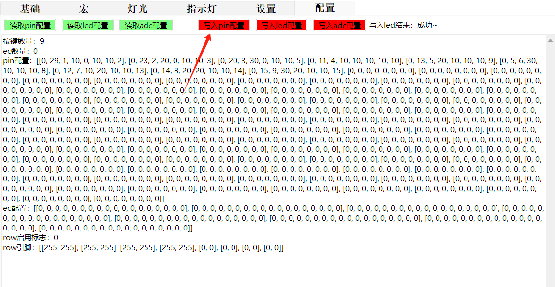
Number of Keys: 9
Number of ECs: 0
PIN configuration: [[0, 29, 1, 10, 0, 10, 10, 2], [0, 23, 2, 20, 0, 10, 10, 3], [0, 20, 3, 30, 0, 10, 10, 5], [0, 11, 4, 10, 10, 10, 10, 10], [0, 13, 5, 20, 10, 10, 10, 9], [0, 5, 6, 30, 10, 10, 10, 8], [0, 12, 7, 10, 20, 10, 10, 13], [0, 14, 8, 20, 20, 10, 10, 14], [0, 15, 9, 30, 20, 10, 10, 15], [0, 0, 0, 0, 0, 0, 0, 0], [0, 0, 0, 0, 0, 0, 0, 0], [0, 0, 0, 0, 0, 0, 0, 0], [0, 0, 0, 0, 0, 0, 0, 0], [0, 0, 0, 0, 0, 0, 0, 0], [0, 0, 0, 0, 0, 0, 0, 0], [0, 0, 0, 0, 0, 0, 0], [0, 0, 0, 0, 0, 0, 0], [0, 0, 0, 0, 0, 0, 0] 0, 0], [0, 0, 0, 0, 0, 0, 0, 0], [0, 0, 0, 0, 0, 0, 0, 0], [0, 0, 0, 0, 0, 0, 0, 0], [0, 0, 0, 0, 0, 0, 0, 0], [0, 0, 0, 0, 0, 0, 0, 0], [0, 0, 0, 0, 0, 0, 0, 0], [0, 0, 0, 0, 0, 0, 0, 0], [0, 0, 0, 0, 0, 0, 0], [0, 0, 0, 0, 0, 0, 0], [0, 0, 0, 0, 0, 0, 0] 0, 0, 0, 0], [0, 0, 0, 0, 0, 0, 0, 0], [0, 0, 0, 0, 0, 0, 0, 0], [0, 0, 0, 0, 0, 0, 0, 0], [0, 0, 0, 0, 0, 0, 0, 0], [0, 0, 0, 0, 0, 0, 0, 0], [0, 0, 0, 0, 0, 0, 0, 0], [0, 0, 0, 0, 0, 0, 0, 0], [0, 0, 0, 0, 0, 0, 0, 0], [0, 0, 0, 0, 0, 0, 0, 0], [0, 0, 0, 0, 0, 0, 0, 0], [0, 0, 0, 0, 0, 0, 0, 0], [0, 0, 0, 0, 0, 0, 0, 0], [0, 0, 0, 0, 0, 0, 0, 0], [0, 0, 0, 0, 0, 0, 0, 0], [0, 0, 0, 0, 0, 0, 0, 0], [0, 0, 0, 0, 0, 0, 0, 0], [0, 0, 0, 0, 0, 0, 0, 0], [0, 0, 0, 0, 0, 0, 0, 0], [0, 0, 0, 0, 0, 0, 0], [0, 0, 0, 0, 0, 0, 0, 0], [0, 0, 0, 0, 0, 0, 0, 0], [0, 0, 0, 0, 0, 0, 0, 0], [0, 0, 0, 0, 0, 0, 0, 0], [0, 0, 0, 0, 0, 0, 0, 0], [0, 0, 0, 0, 0, 0, 0, 0], [0, 0, 0, 0, 0, 0, 0, 0], [0, 0, 0, 0, 0, 0, 0, 0], [0, 0, 0, 0, 0, 0, 0, 0], [0, 0, 0, 0, 0, 0, 0, 0], [0, 0, 0, 0, 0, 0, 0, 0], [0, 0, 0, 0, 0, 0, 0, 0], [0, 0, 0, 0, 0, 0, 0, 0], [0, 0, 0, 0, 0, 0, 0, 0], [0, 0, 0, 0, 0, 0, 0, 0], [0, 0, 0, 0, 0, 0, 0, 0], [0, 0, 0, 0, 0, 0, 0, 0], [0, 0, 0, 0, 0, 0, 0], [0, 0, 0, 0, 0, 0, 0], [0, 0, 0, 0, 0, 0, 0] 0, 0, 0], [0, 0, 0, 0, 0, 0, 0, 0], [0, 0, 0, 0, 0, 0, 0, 0], [0, 0, 0, 0, 0, 0, 0, 0], [0, 0, 0, 0, 0, 0, 0, 0], [0, 0, 0, 0, 0, 0, 0, 0], [0, 0, 0, 0, 0, 0, 0, 0], [0, 0, 0, 0, 0, 0, 0, 0], [0, 0, 0, 0, 0, 0, 0, 0], [0, 0, 0, 0, 0, 0, 0], [0, 0, 0, 0, 0, 0, 0] 0, 0, 0, 0, 0], [0, 0, 0, 0, 0, 0, 0, 0], [0, 0, 0, 0, 0, 0, 0, 0], [0, 0, 0, 0, 0, 0, 0, 0], [0, 0, 0, 0, 0, 0, 0, 0], [0, 0, 0, 0, 0, 0, 0, 0], [0, 0, 0, 0, 0, 0, 0, 0], [0, 0, 0, 0, 0, 0, 0, 0], [0, 0, 0, 0, 0, 0, 0, 0], [0, 0, 0, 0, 0, 0, 0, 0], [0, 0, 0, 0, 0, 0, 0, 0], [0, 0, 0, 0, 0, 0, 0, 0], [0, 0, 0, 0, 0, 0, 0, 0], [0, 0, 0, 0, 0, 0, 0, 0], [0, 0, 0, 0, 0, 0, 0, 0], [0, 0, 0, 0, 0, 0, 0, 0], [0, 0, 0, 0, 0, 0, 0, 0], [0, 0, 0, 0, 0, 0, 0, 0], [0, 0, 0, 0, 0, 0, 0, 0], [0, 0, 0, 0, 0, 0, 0, 0], [0, 0, 0, 0, 0, 0, 0, 0], [0, 0, 0, 0, 0, 0, 0, 0], [0, 0, 0, 0, 0, 0, 0, 0], [0, 0, 0, 0, 0, 0, 0, 0], [0, 0, 0, 0, 0, 0, 0, 0], [0, 0, 0, 0, 0, 0, 0, 0], [0, 0, 0, 0, 0, 0, 0, 0], [0, 0, 0, 0, 0, 0, 0, 0]]
EC configuration: [[0, 0, 0, 0, 0, 0, 0, 0, 0, 0, 0, 0, 0, 0, 0, 0, 0], [0, 0, 0, 0, 0, 0, 0, 0, 0, 0, 0, 0, 0, 0, 0, 0, 0], [0, 0, 0, 0, 0, 0, 0, 0, 0, 0, 0, 0, 0, 0, 0, 0, 0], [0, 0, 0, 0, 0, 0, 0, 0, 0, 0, 0, 0, 0, 0, 0, 0, 0, 0], [0, 0, 0, 0, 0, 0, 0, 0, 0, 0, 0, 0, 0, 0, 0, 0, 0], [0, 0, 0, 0, 0, 0, 0, 0, 0, 0, 0, 0, 0, 0, 0, 0, 0, 0, 0, 0, 0], [0, 0, 0, 0, 0, 0, 0, 0, 0, 0, 0, 0, 0, 0, 0, 0, 0, 0, 0, 0, 0, 0, 0, 0, 0, 0, 0, 0, 0, 0, 0, 0, 0, 0, 0, 0, 0, 0, 0, 0, 0, 0, 0, 0, 0, 0, 0, 0, 0, 0, 0, 0, 0, 0, 0, 0, 0, 0, 0, 0, 0, 0, 0, 0, 0, 0, 0, 0, 0, 0, 0], [0, 0, 0, 0, 0, 0, 0, 0, 0, 0, 0, 0, 0, 0, 0, 0, 0, 0, 0], [0, 0, 0, 0, 0, 0, 0, 0, 0, 0, 0, 0, 0, 0, 0, 0, 0], [0, 0, 0, 0, 0, 0, 0, 0, 0, 0, 0, 0, 0, 0, 0, 0, 0, 0]]
row enable flag: 0
row pin: [[255, 255], [255, 255], [255, 255], [255,
b. Configure LEDs: Write the following LED configuration in the configuration
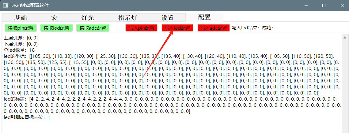
: Upper layer pin: [0, 0]
Lower layer pin: [0, 0]
Total number of LEDs: 18
LED coordinates: [[105, 30], [110, 30], [120, 30], [125, 30], [130, 30], [135, 30], [135, 40], [130, 40], [120, 40], [110, 40], [105, 40], [105, 50], [110, 50], [120, 50], [130, 50], [135, 50], [125, 55], [115, 55], [0, 0], [0, 0], [0, 0], [0, 0], [0, 0], [0, 0], [0, 0], [0, 0], [0, 0], [0, 0], [0, 0], [0, 0], [0, 0], [0, 0], [0, 0], [0, 0], [0, 0], [0, 0], [0, 0], [0, 0], [0, 0], [0, 0], [0, 0], [0, 0], [0, 0], [0, 0], [0, 0], [0, 0], [0, 0], [0, 0], [0, 0], [0, 0], [0, 0], [0, 0], [0, 0], [0, 0], [0, 0], [0, 0], [0, 0], [0, 0], [0, 0], [0, 0], [0, 0], [0, 0], [0, 0], [0, 0], [0, 0], [0, 0], [0, 0], [0, 0], [0, 0], [0, 0], [0, 0], [0, 0], [0, 0], [0, 0], [0, 0], [0, 0], [0, 0], [0, 0], [0, 0], [0, 0], [0, 0], [0, 0], [0, 0], [0, 0], [0, 0], [0, 0], [0, 0], [0, 0], [0, 0], [0, 0], [0, 0], [0, 0], [0, 0], [0, 0], [0, 0], [0, 0], [0, 0], [0, 0], [0, 0], [0, 0], [0, 0], [0, 0], [0, 0], [0, 0], [0, 0], [0, 0], [0, 0], [0, 0], [0, 0], [0, 0], [0, 0], [0, 0], [0, 0], [0, 0], [0, 0], [0, 0], [0, 0], [0, 0], [0, 0], [0, 0], [0, 0], [0, 0], [0, 0], [0, 0], [0, 0], [0, 0], [0, 0], [0, 0], [0, 0], [0, 0], [0, 0], [0, 0], [0, 0], [0, 0], [0, 0], [0, 0], [0, 0], [0, 0], [0, 0], [0, 0], [0, 0], [0, 0], [0, 0], [0, 0], [0, 0], [0, 0], [0, 0], [0, 0], [0, 0], [0, 0], [0, 0], [0, 0], [0, 0], [0, 0], [0, 0], [0, 0], [0, 0], [0, 0], [0, 0], [0, 0]]
LED markings: [4, 2, 2, 4, 2, 4, 4, 2, 2, 2, 4, 4, 2, 2, 2, 4, 4, 4, 0 ... 0, 0, 0, 0, 0, 0, 0, 0, 0, 0, 0, 0, 0, 0, 0, 0, 0, 0, 0, 0, 0, 0, 0, 0, 0, 0, 0, 0, 0, 0, 0, 0, 0, 0, 0, 0, 0, 0, 0, 0, 0, 0, 0, 0, 0, 0, 0, 0, 0, 0, 0, 0, 0, 0, 0, 0, 0, 0, 0, 0, 0, 0, 0, 0, 0, 0, 0, 0, 0, 0, 0, 0, 0, 0, 0, 0, 0, 0, 0, 0, 0, 0, [0, 0, 0, 0, 0, 0, 0, 0]
LED pin transpose flag: 1
c. Write ADC configuration: No operation is required since Bluetooth and ADC pins are not used.
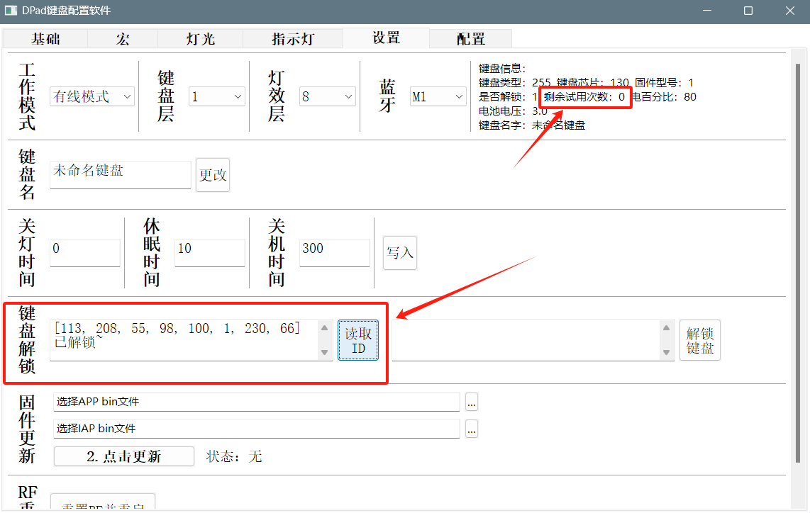
d. Keyboard unlock: The keyboard has 10 trial uses before unlocking; unlocking is required for long-term use. [For DIY enthusiasts, unlock codes are provided free of charge; please include them in the comments.]
III. Firmware and Host Computer
The firmware and host computer are in the attachments. [The host computer exceeds the limit, so it has been split into two compressed files; download and extract them together.]

 . Note: The 100BF capacitor design uses two sets of pads, one for soldering and one as a spare
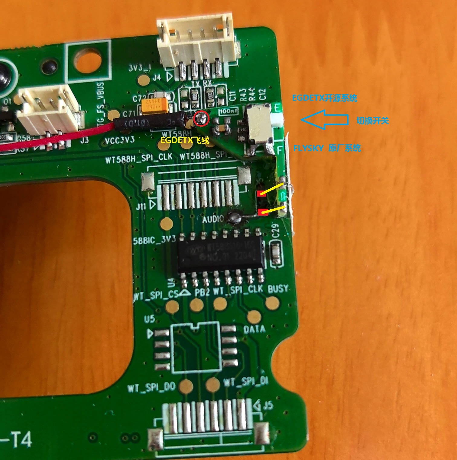
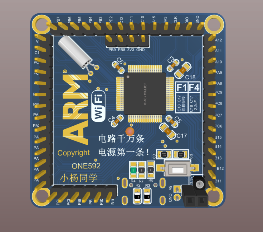
 has been batch tested and used in self-made remote controls, computer design competition main controllers, and electronic design competition main controllers (around 2021).
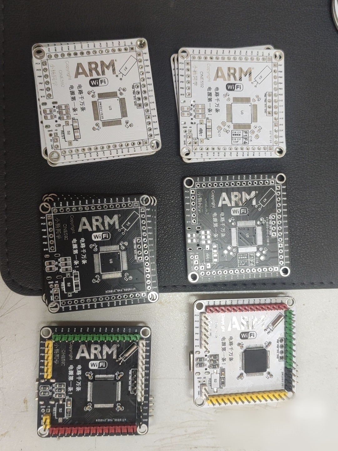
 Purchase Link: https://m.tb.cn/h.5Ud93HJ?tk=G1Z7dAgNJQf CZ0001
  The price is still very affordable at 68 cents each, and importantly, shipping is free. No problems have been found after using it for a while.
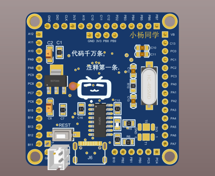
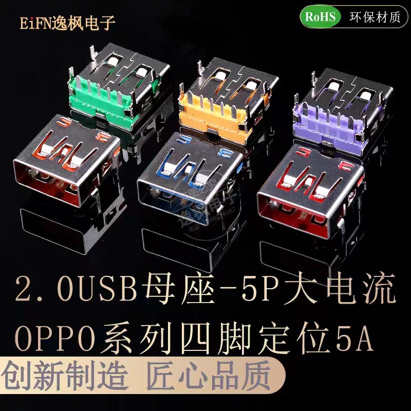
  Purchase Link: https://m.tb.cn/h.5fP9TYE?tk=21XgdAgLRp5 CZ0001
 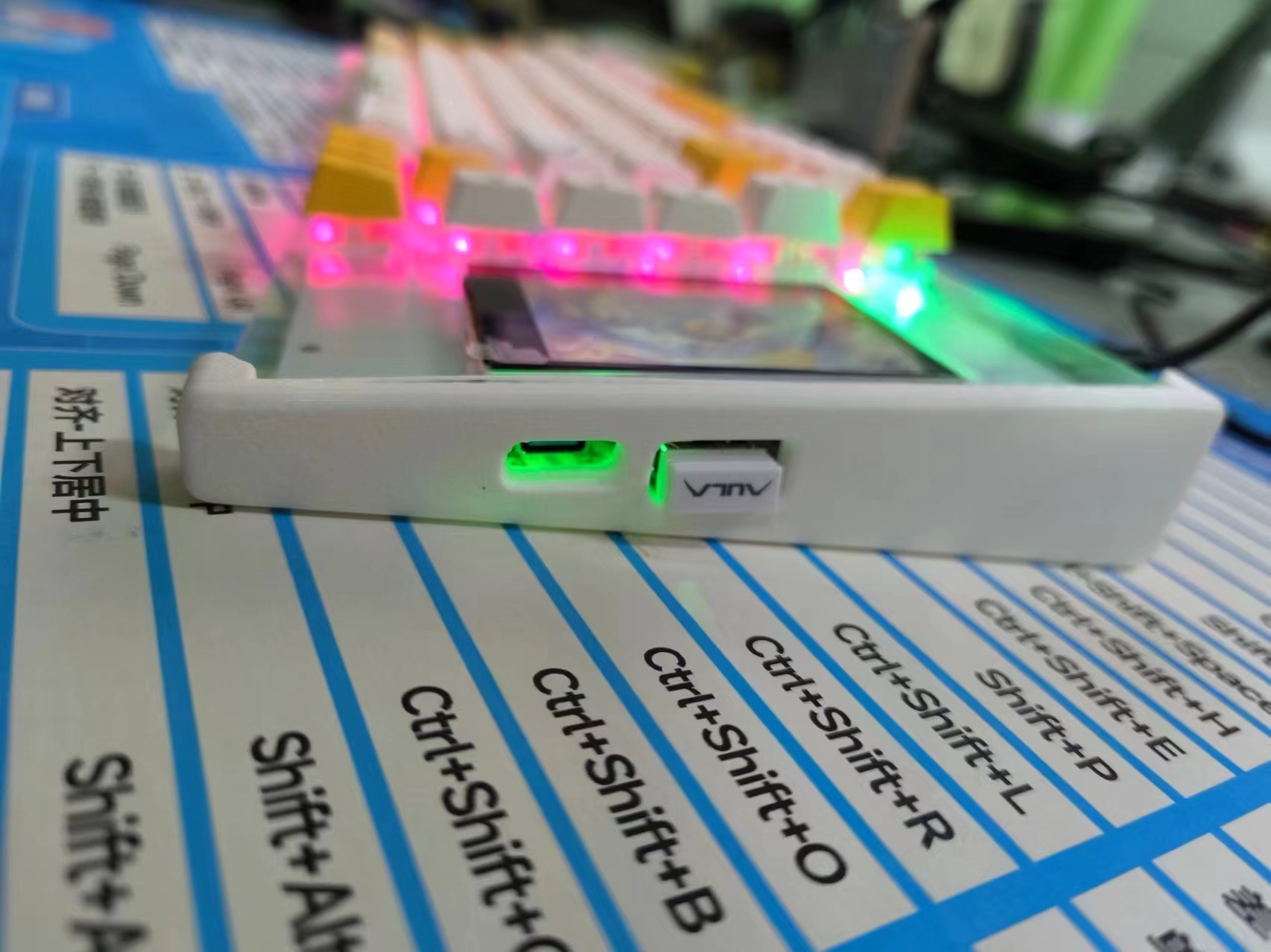 Bottom
 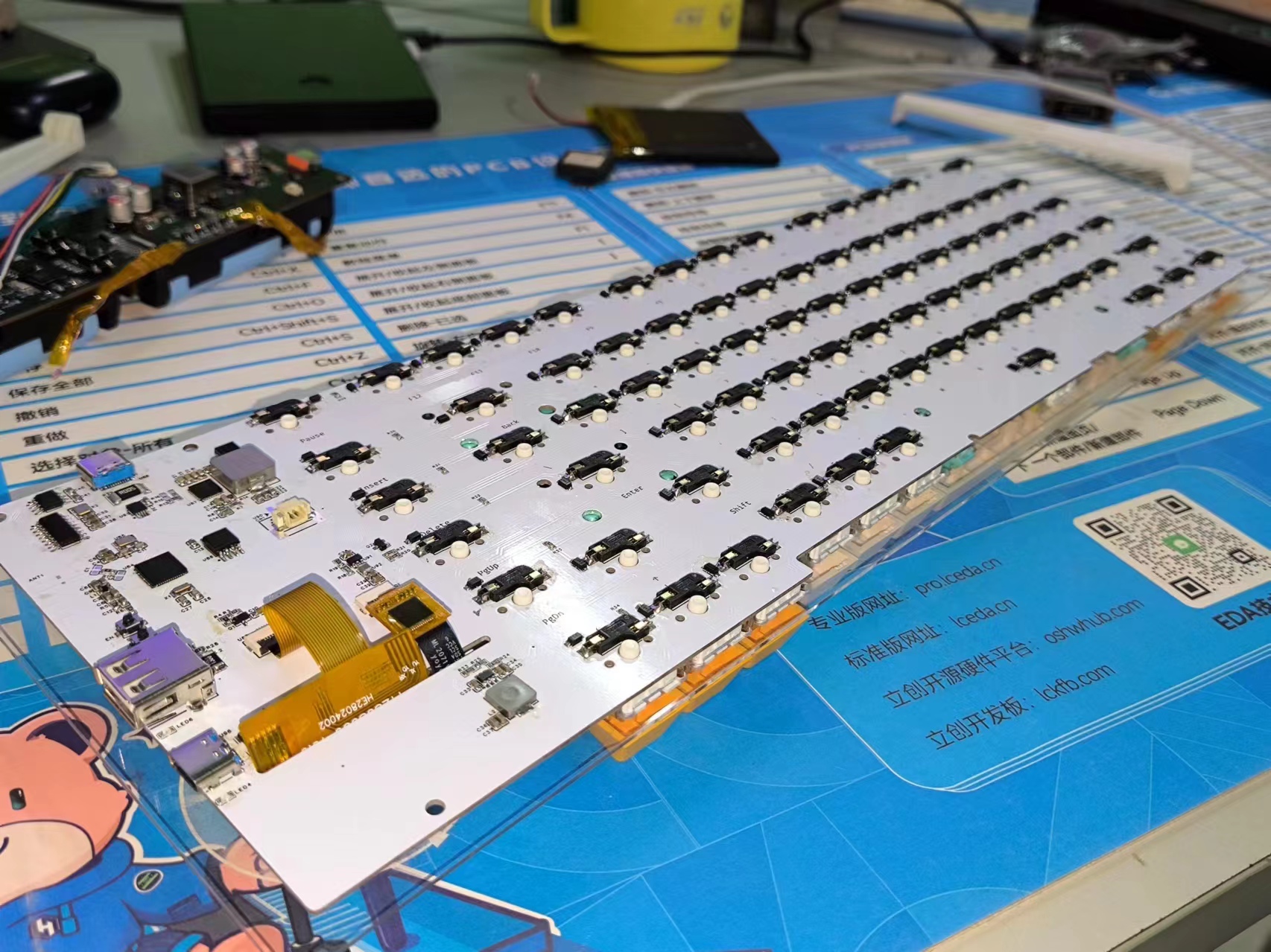 and front:
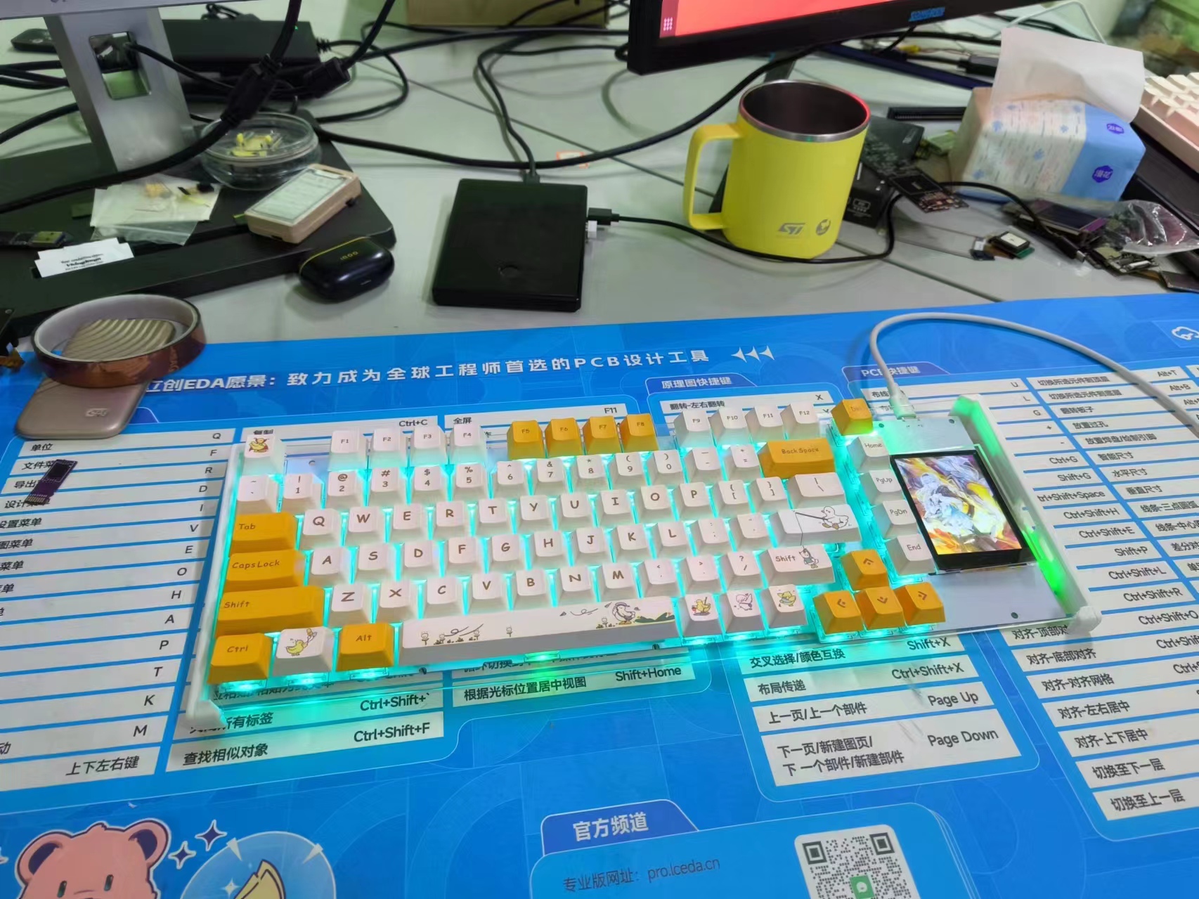
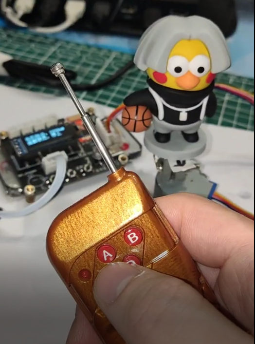
 See the video preview (HDR seems to have problems, please bear with it for now).


 京公网安备 11010802033920号

 VI-242MX


