Chameleon Ultra Replica RFID
Detection Card 1:1 Full-Function Replica Multifunctional RFID Access Control Tool Multifunctional Access Control Card Simulator Reader/Writer Chameleon Ultra Ultra Latest Version ID Card Signal Sensitivity 345UH, nearly double the official 175UH. This device can simulate RFID cards (13.65MHz M1 series IC cards and 125kHz low-frequency EM41XX/T5577 ID cards). It has 8 card slots, each capable of simulating one IC card and one ID card. It can simultaneously simulate 16 cards (8 IC cards + 8 ID cards). It can read IC cards and ID cards, write cards, and simulate cards
. It can also execute Nested, Darkside, StaticNested, Hardnested, and MFKEY32 commands. The v2 attack can directly decrypt the M1 semi-encrypted card. The detection function can crack third-generation, vulnerability-free encryption cards.
This device comes with Bluetooth 5.0 and a USB-C port. Android phones can connect via Bluetooth and OTG. PCs and Macs can connect directly using a Type-C data cable. Apple phones can only connect via Bluetooth. The device uses
a built-in 100mAh rechargeable lithium battery, not the older button battery. According to official data, a single charge and 8 card swipes per day can last up to 6 months.
The surface is covered with transparent epoxy resin, which effectively protects the components and improves aesthetics.
English name: Chameleon Ultra. Chinese name: 变色龙Ultra. Body size: 4cm*2.4cm*0.8cm.
The original HF and LF corresponding 6-layer boards have all been changed to 4-layer boards, making it easy for anyone to replicate, only sacrificing half the signal strength of the ID card. There is no significant impact on the IC card signal. Immersion gold processing is used as much as possible.
The functionality is the same as the original,
and the firmware and APP are the same.
The finished product has been verified; the functionality is the same as the original except for the poor LF signal.
You can add your own patterns to the LF backplate, remember to include windows.
Note: This project strictly follows the original open-source license GPL3.0.
Replica exchange group: 573274730. The mid-frame file is in the group files. Protective cases are available at the seafood market; the link has been updated. A new white horizontal version has been added to the seafood market
>>>>>
DM me for the seafood market link. The one on Xianyu is a black 0.8mm thick board with the same process as the original 6-layer board: immersion gold, resin-filled vias, hollow tray, and electroplated cap. The 0.8mm thickness greatly reduces the impact of board thickness on signal strength.
The error of insufficient LF line spacing of less than 5mil has been corrected.
The battery uses 302020
screws. Screws should be M1.6 * (5-7). For a board thickness of 0.8mm, use 5mm; for 1.2mm, use 6mm; for 1.6mm, use 7mm.
SMT nuts should have a diameter of 3mm * M1.6 * 0.5mm (height) * diameter of 2.1mm * 0.8mm (height ).
The LF backplate must have a magnetic shielding sticker; otherwise, high and low frequency interference will cause low frequency to malfunction.
Important note: The resonant capacitor needs to be changed to 8.76NF. Precision is not required, just close to 8.76NF is fine. The values that need to be changed are C10, C33, and C34. The sum of these three values should be close to 8.76NF.

ultra.hex
JLink_Windows_V632b.exe
RRG original 6-layer file.zip
Gerber_4-layer LF board production files.zip
Gerber_4-layer HF board fabrication files.zip
PDF_Chameleon Ultra Reissue.zip
Altium_Chameleon Ultra Reissue.zip
PADS_Chameleon Ultra Reissue.zip
BOM_Chameleon Ultra Reissue.xlsx
91829
CH571F/CH573F/CH582F/CH583F Module
A CH57XF and CH58XF module, designed according to the form factor of the ESP32C3 module, has been verified to be programmable.
The chip can be replaced with CH57X or CH58X, a module designed according to the ESP32C3 module shape. However, only 3V3, GND, TX, and RX are compatible with the ESP32C3. You can modify D+ and D- to match the ESP32C3 yourself; I was too lazy to do so. The buttons don't need to be soldered. The inductor can be replaced with a 0R resistor (if you don't want to enable DC-DC). The 32k crystal oscillator doesn't need to be soldered (if you don't want to use a Bluetooth host).
IMG_0324.HEIC
IMG_0323.HEIC
IMG_0322.HEIC
PDF_CH571F-CH573F-CH582F-CH583F module.zip
Altium_CH571F_CH573F_CH582F_CH583F module.zip
PADS_CH571F_CH573F_CH582F_CH583F module.zip
PDF_CH571F-CH573F-CH582F-CH583F module.zip
Altium_CH571F_CH573F_CH582F_CH583F module.zip
PADS_CH571F_CH573F_CH582F_CH583F module.zip
BOM_CH571F_CH573F_CH582F_CH583F module.xlsx
91831
Mini Thermometer and Hygrometer
Type C Mini Portable Thermometer and Hygrometer
Type-C mini portable thermometer and hygrometer; microcontroller source code is attached.


07.TypeCWenShiDu.zip
PDF_Mini Thermometer and Hygrometer.zip
Altium Mini Thermometer and Hygrometer.zip
PADS Mini Thermometer and Hygrometer.zip
BOM_Mini Thermohygrometer.xlsx
91833
STM32F4-based core board
The core board, based on the STM32F407VET6 main chip, integrates commonly used functions such as OLED and BLE.
I wanted to make a smart remote-controlled car toy for my unborn child, controlled by an STM32F4, hence the idea of creating a core board.
This core board uses the STM32F407VET6 main chip, measuring 60*70mm, with pins extended on both sides for easy expansion with power strips. It also integrates common functions such as OLED and BLE. Features
include: 1. All useful pins are brought out, with additional 3.3V and 5V power pins for peripherals;
2. Power indicator and indicator lights on two I/O ports for easy debugging;
3. Built-in CH340C module for direct serial connection to a computer, supporting one-click download of software like FlyMCU;
4. SWD download and debugging;
5. Support for common 0.96-inch I2C OLED screens;
6. Support for 5V Bluetooth for connection to USART3;
7. Support for the MPU6050 sensor;
8. One M3 screw mounting position at each of the four corners.
webwxgetmsgimg.jfif
1579907207.mp4
PDF_STM32F4-based core board.zip
Altium_Based on STM32F4 Core Board.zip
PADS_Based on STM32F4 Core Board.zip
BOM_Based on STM32F4 Core Board.xlsx
91836
Sky-Star Extension Board
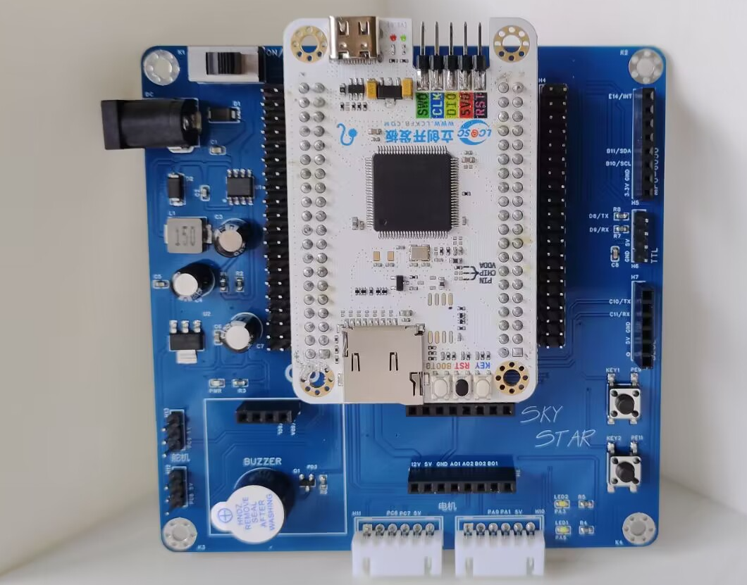
This expansion board is specifically designed for LCSC SkyStar development boards, making it an ideal choice for control-related problems in electronics design competitions due to its abundant pin resources and high cost-effectiveness. It not only integrates commonly used peripheral modules such as motors and OpenMV communication, but also features easily expandable external headers, ensuring functional diversity and flexibility.
Preface:
This expansion board, specifically designed for the LCSC SkyStar development board, offers great convenience with its compact 10cm square size and free PCB fabrication service. It features a rich array of peripheral interfaces, including two servo interfaces, two buttons, LEDs, an active buzzer, a TB6612 motor control module, a Bluetooth communication module, an OpenMV communication/TTL module, an MPU-6050 module, and a 0.96-inch OLED screen module. The board also features the SkyStar logo and the LCSC logo, enhancing product brand recognition.
Power Supply :
The expansion board uses a 12V DC power connector for power supply stability. A reverse polarity protection diode is installed at the power input to effectively prevent damage caused by reverse polarity. Additionally, a slide switch allows for easy power control.

This expansion board features a meticulously designed two-stage power conversion circuit to ensure a stable power supply for peripherals with varying voltage requirements:
a. To step down the 12V DC input to 5V, a Texas Instruments TPS5430DDAR DC-DC step-down converter is used. This chip is known for its high efficiency and stability, making it suitable for providing the required 5V power to onboard devices;
b. Further stepping down the 5V to 3.3V utilizes an AMS1117-3.3LDO low-dropout linear regulator. This regulator is favored for its low noise and high-precision output, ensuring a stable 3.3V power supply for voltage-sensitive electronic devices.

The expansion board measures 10cm x 10cm and can be custom-made free of charge by JLCPCB.
Designed with electronic competition needs in mind, this expansion board integrates multiple functional modules to support a wide range of applications:
it features two servo interfaces for convenient control of robotic arms or other precision motion devices;
two buttons for easy user interaction and simple control logic;
integrated LEDs for status indication or visual feedback;
and an integrated active buzzer for audible alerts.
It can be equipped with the TB6612 motor control module, capable of driving dual motors, suitable for projects requiring motor control.
It can also be equipped with a Bluetooth communication module, allowing wireless connectivity and remote control.
It provides an OpenMV communication and TTL module interface, supporting image processing and machine vision tasks.
It can be equipped with an MPU-6050 module for motion tracking and attitude detection.
It can also be equipped with a 0.96-inch OLED screen module for displaying information and a user interface.
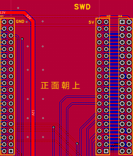
The expansion board's port design uses a 2x20 header with a 2.54mm pitch, facilitating connection and expansion with other devices or modules. Other features
include the SkyStar logo and the JLCPCB logo, as
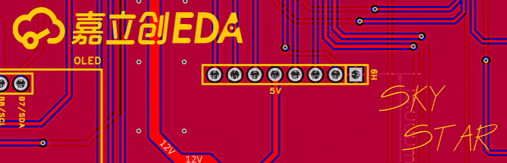
well as SkyStar development board installation instructions (SWD is the compilation and programming header area).

PDF_Sky-Star Extension Board.zip
Altium_Sky-Star Extension Board.zip
PADS_Sky-Star Expansion Board.zip
BOM_Sky-Star Extension Board.xlsx
91837
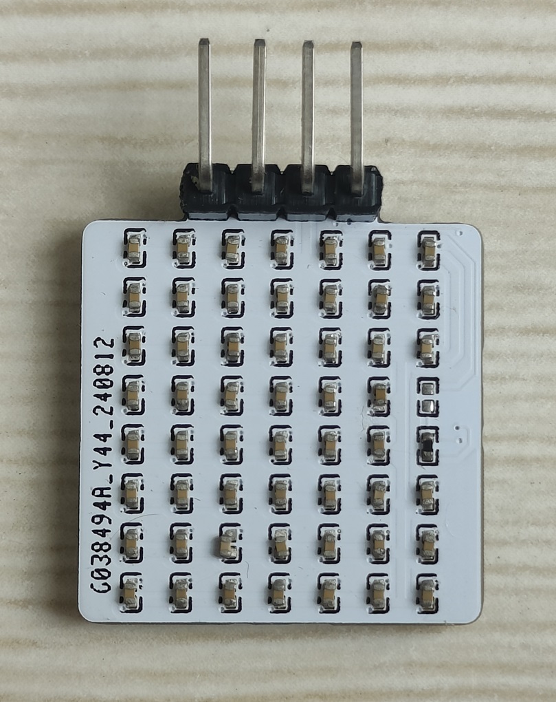
WS2812B LED panel 8×8
The dot matrix LED board composed of WS2812 LEDs has a resolution of 8x8.
LED details : WS2812B;
Power: <6W
; Quantity: 64;
Images

PDF_WS2812B Light Board 8×8.zip
Altium_WS2812B LED board 8×8.zip
PADS_WS2812B LED board 8×8.zip
BOM_WS2812B Light Board 8×8.xlsx
91838
[Based on the LCSC Development Board Electronic Design Competition] Dikuoxing Simple Digital Multimeter
A simple digital multimeter based on the LCSC GeoStar development board
I. Design Objective:
Based on the LCSC DiKuoXing development board (STM32F103C8T6 main controller), design a simple digital multimeter capable of measuring voltage, current, resistance, capacitance, and forward voltage drop of diodes. II. Hardware Design:
The basic circuit
uses two rows of 20-pin headers connected to the development board
. Due to the low power consumption of the expansion board, power is directly obtained from the development board.
The display uses a 0.96-inch OLED screen for easy and clear
operation. Buttons switch measurement modes and ranges; each button is connected in parallel with a 1uF capacitor for hardware debouncing.
LED indicators are provided at the measurement interface for each mode for ease of use.
The voltage measurement circuit
uses voltage divider resistors and MOSFET selection to achieve three ranges: 3-divider, 2-divider, and 1-divider.
The STM32 internal ADC
current measurement circuit
uses a 100 milliohm sampling resistor
and an LM358 operational amplifier to amplify the voltage across the sampling resistor.
The STM32 internal ADC
resistance measurement circuit
employs multiple sets of voltage divider resistors with different resistance values to achieve five resistance ranges.
A MOSFET selection network is used to switch between ranges. The
capacitance measurement circuit
uses an NE555 timer and the capacitor under test to form an astable oscillation circuit. The oscillation frequency is captured and measured using the STM32's timer input, indirectly calculating the capacitance value.
The diode measurement circuit
uses a transistor with a small base current to simulate a constant current source, limiting the current through the diode to 10-20mA. The voltage across the diode is then the forward voltage drop. The software design
utilizes the STM32 standard library.
The OLED display driver is ported from Jiangxie Technology's driver files.
External interrupts and timer interrupts are used to read button inputs, with good debouncing.
ADC self-calibration is enabled.
Testing showed that all modules functioned normally, basically achieving the design goals.
Due to limitations in ADC accuracy and the accuracy of voltage divider/sampling resistors, there will be some error between the measurement results and the standard. After adjusting the parameters in the calculation model, the error is generally reduced to 5%.
output_image.jpg
Menu.mp4
Voltage.mp4
Voltage 2.mp4
Current.mp4
resistor.mp4
Capacitor.mp4
diode.mp4
The program is burned to the project.hex file.
PDF_[Based on the LCSC Development Board Electronic Design Competition] Di Kuo Xing Simple Digital Multimeter.zip
Altium_ [Based on the LCSC Development Board Electronic Design Competition] Di Kuo Xing Simple Digital Multimeter.zip
PADS_[Based on the LCSC Development Board Electronic Design Competition] Di Kuo Xing Simple Digital Multimeter.zip
BOM_ [Based on the LCSC Development Board Electronic Design Competition] Dikuoxing Simple Digital Multimeter.xlsx
91839
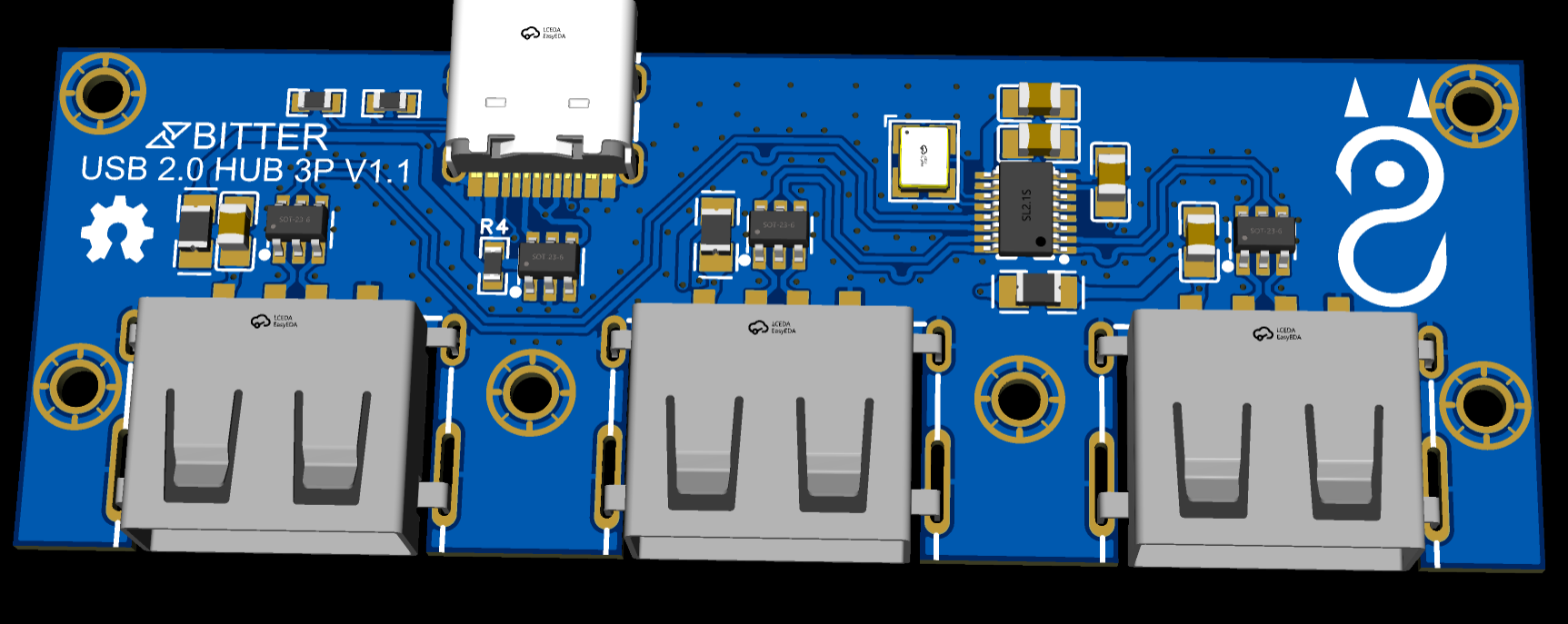
Flat USB 2.0 HUB
Based on the SL2.1S, we minimized the PCB area and height, removed one of the four USB ports, and designed a 3D-printed casing.
The SL2.1S is simply a smaller version of the SL2.1A, packaged in an SSOP-16 package. Functionally identical, it expands to include four ports, but to reduce PCB size, only three are included. In most cases, I'll only use three: two for keyboard and mouse receivers, and the remaining one for anything else. Its flat shape makes it easy to carry in a bag, and it can also be attached to the back of a tablet with double-sided tape.
Testing confirmed it operates at standard USB 2.0 speeds, with a maximum read speed of around 38MB/s for a USB flash drive.
------------------
![image.png]
A few points to note:
1. I used a 12.5pF crystal oscillator for the 12MHz frequency; I'm not sure if other specifications will work.
2. I recommend a 1mm thick PCB because the Type-C connector's mounting feet are short, and a 1mm board is easier to solder.
3. However, a 1mm board is quite flexible, so it's best to use a housing. The board has M2 screw holes.
4. This recessed USB-A connector comes in two similar models, one 11.0mm and the other 10.6mm. I modified the mounting pads on the housing to make it compatible with both types.
I'll 3D print the housing later.
------------------
The housing model is finished, but I can't get my hands on a printer yet. The overall effect is as follows:
![image.png]

To reduce the size, the housing doesn't completely cover the PCB and USB interface. A window on the top cover exposes the metal casing of the USB-A connector, but it doesn't have much of an impact. The housing's length and width are the same as the PCB, and the overall thickness is approximately 9mm. Both the top and bottom shells can be printed directly without support. M2 countersunk self-tapping screws, 8mm in length, are recommended. Countersunk holes are made on the bottom cover.
![image.png]

By the way, this is what the inside of the top cover looks like:
![image.png]

The STL model is attached.
Top cover .stl
Bottom cover.stl
PDF_USB2.0 HUB Flat Design.zip
Altium_USB2.0 HUB Flat Design.zip
PADS_USB2.0 HUB Flat Design.zip
BOM_USB2.0 HUB Flattened.xlsx
91840
electronic


 京公网安备 11010802033920号

 C222J11S105QF


