 2. Fixing the Infrared Thermal Imaging Image:
 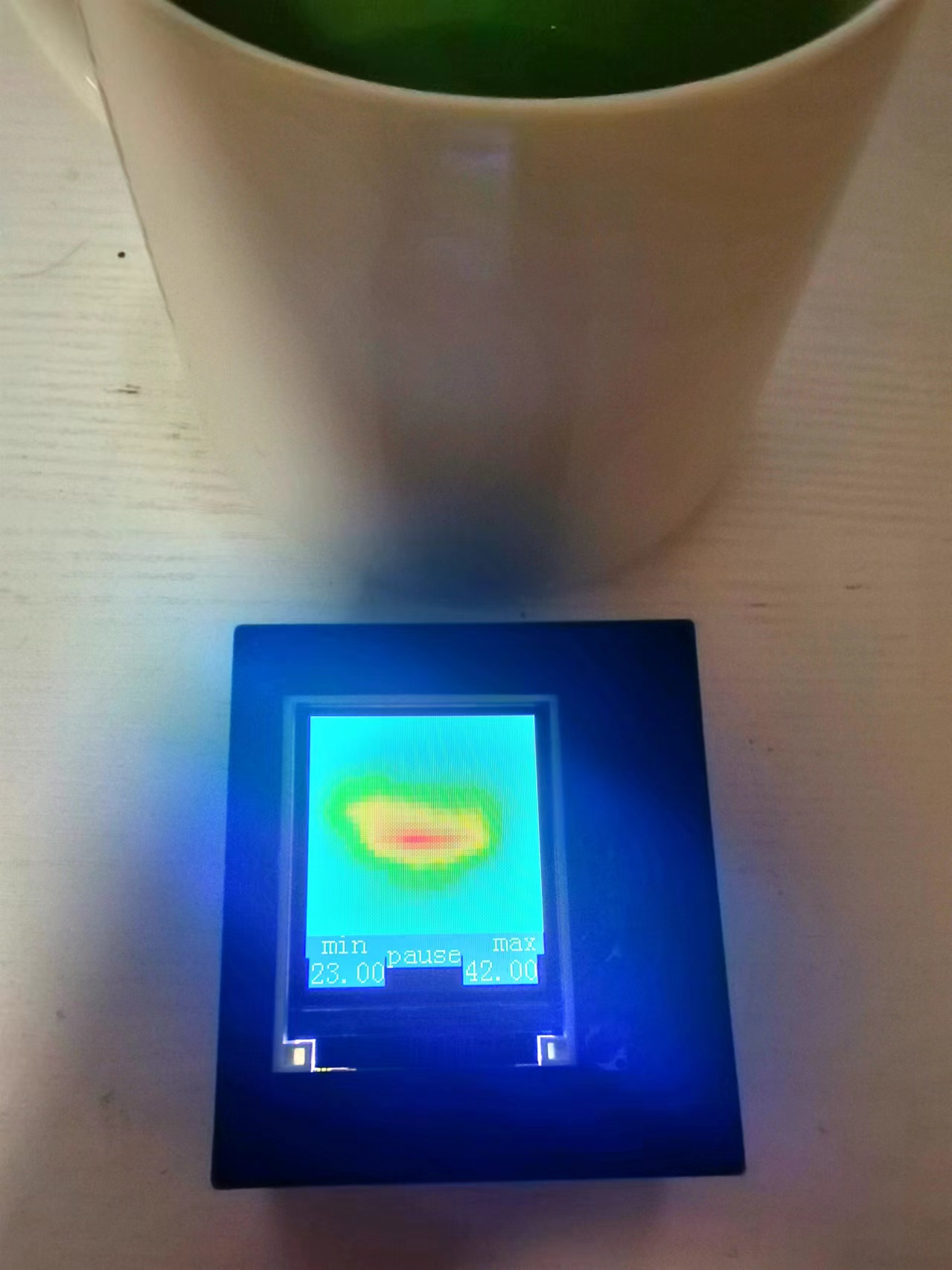 3. Displaying the Highest Temperature Point:
  4: Long press the button to turn off the screen.
 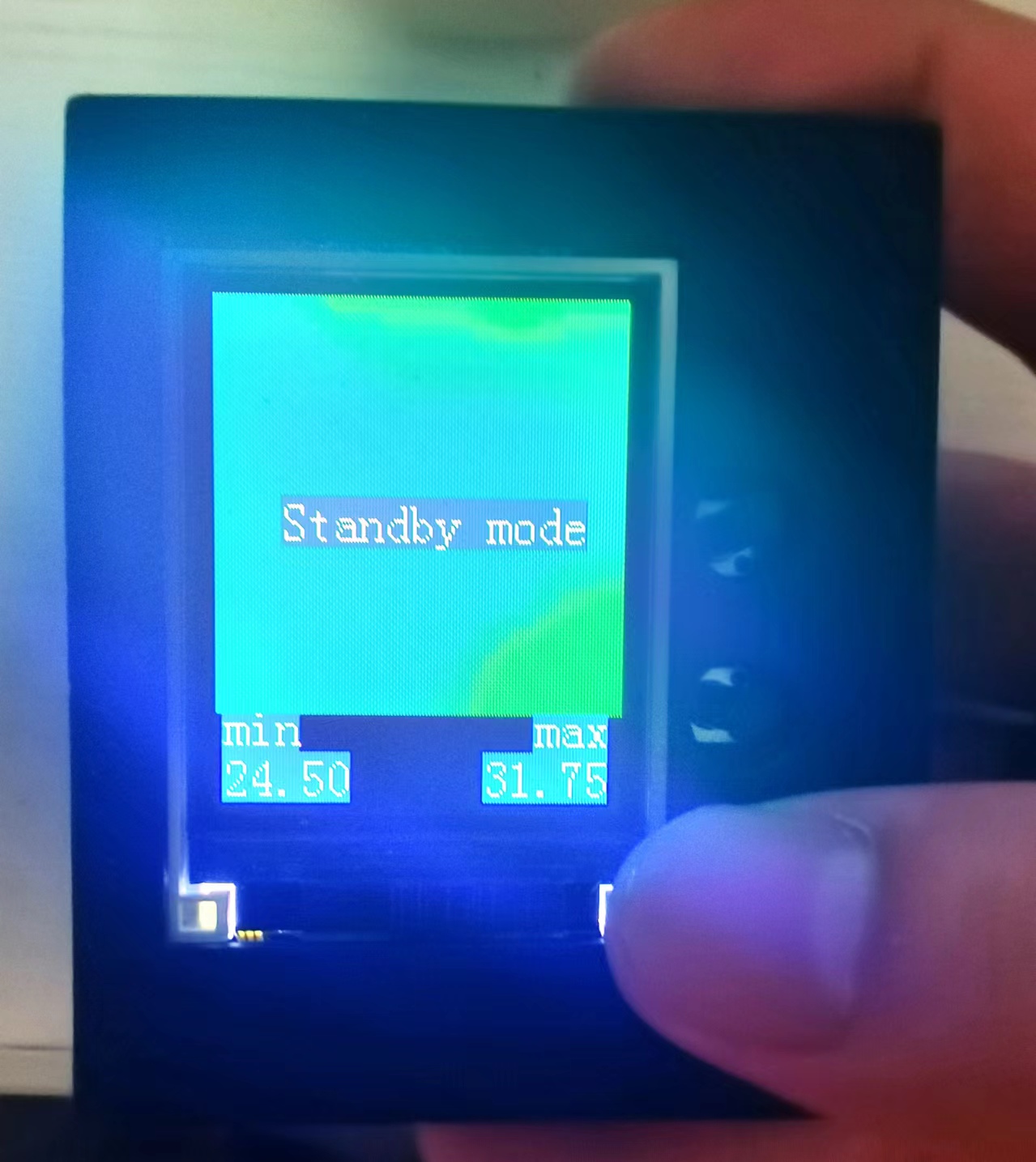 5: Real-time acquisition, display, and saving
 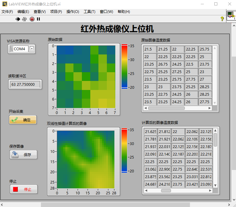 Project Parameters:
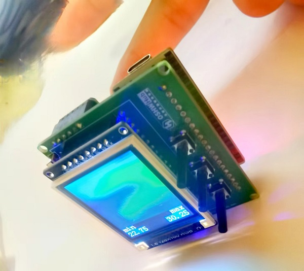
  The front layer, as shown in the diagram, houses the display module and three long-handled button control modules.
  Removing the display module reveals the middle layer, as shown in the diagram, which contains the lithium battery charging/discharging module, the SD card module, and the power switch. Power is supplied
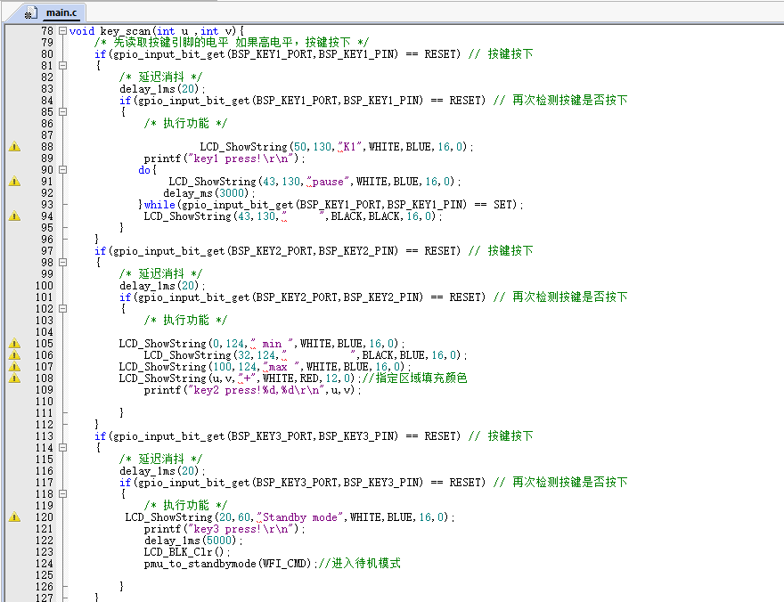
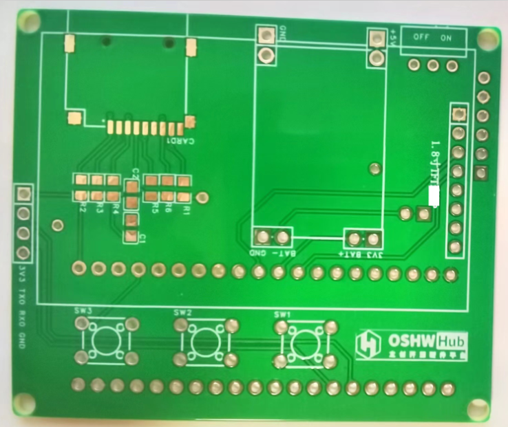
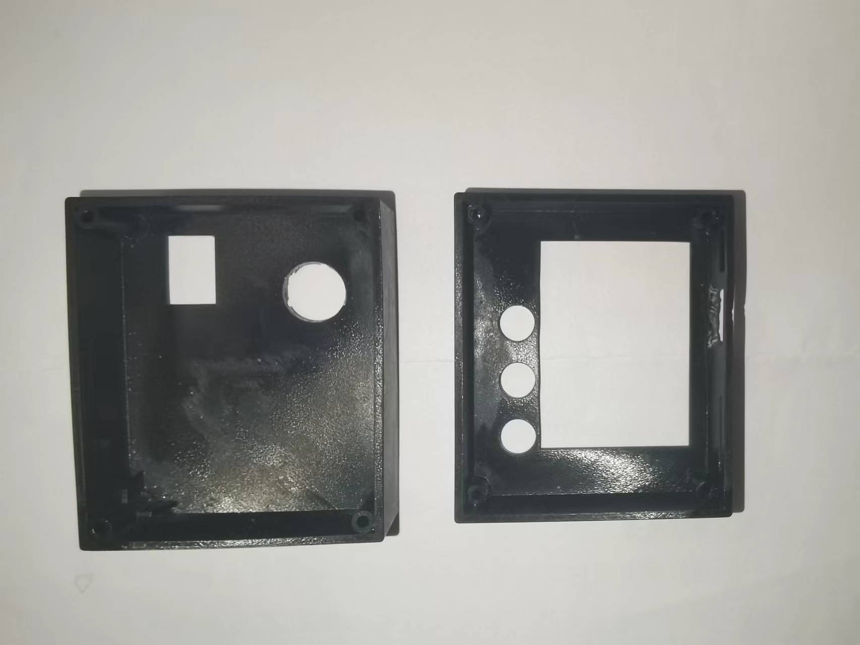
 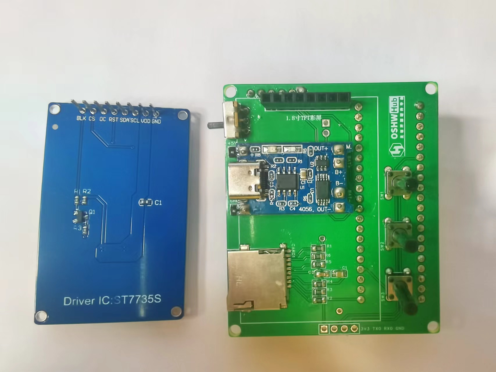 via the lithium battery and its charging/discharging module or a Type-C port. The power switch controls whether the lithium battery is connected to the circuit. The three buttons control the display and interaction with the infrared thermal imager. The LCSC development board serves as the main control board. Software Code The core code of this project displays and sends the data collected by the infrared thermal imaging module, and handles user interaction. Infrared thermal imaging data acquisition, processing, display, and transmission code: The button control interaction logic code is as follows: Links to some of the code referenced in this project are as follows: AMG8833 8x8 thermal imaging sensor_amg8833 Chinese datasheet ; C language implementation code for bilinear interpolation function. Important notes: When soldering pin headers and sockets, the hot air gun temperature should not be set too high. Excessive temperature can cause unmelted solder to flow through the holes to the other side of the PCB, causing a short circuit between two adjacent drilled holes! When charging the lithium battery, press the third button to enter standby mode to reduce power consumption. A hole needs to be made on the back of the casing to prevent the development board's pin headers from interfering with the back casing. Additionally, the side USB hole should be flush with the side opening during soldering; otherwise, the charging interface will be interfered with by the casing, preventing the charging cable from being inserted. The assembly process involves soldering surface-mount components, such as the pull-up resistors, capacitors, and SD card slot for the SD card module. Next, solder headers, sockets, and through-hole components, such as buttons, lithium battery charging/discharging modules, display sockets, development board sockets, and infrared thermal imaging module sockets (so that the sockets can be easily removed from the corresponding modules). Finally, insert the display, infrared thermal imaging module, and development board into their respective sockets. The front view of the hardware PCB for this project is shown below. The back view of the hardware PCB for this project is shown below. In addition, this project also designed corresponding upper and lower housings, as shown in the following figures. After the PCBA is completed, the bare device is placed inside the housing and secured with thin screws. The assembled device and its usage are shown below: Bare device without housing: Hardware measurement with housing: Finally, thank you for your support, JLCPCB. This project may have shortcomings; please leave comments for discussion. Thank you.
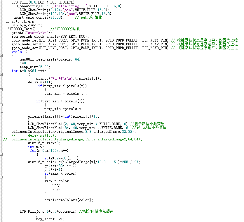


All reference designs on this site are sourced from major semiconductor manufacturers or collected online for learning and research. The copyright belongs to the semiconductor manufacturer or the original author. If you believe that the reference design of this site infringes upon your relevant rights and interests, please send us a rights notice. As a neutral platform service provider, we will take measures to delete the relevant content in accordance with relevant laws after receiving the relevant notice from the rights holder. Please send relevant notifications to email: bbs_service@eeworld.com.cn.
It is your responsibility to test the circuit yourself and determine its suitability for you. EEWorld will not be liable for direct, indirect, special, incidental, consequential or punitive damages arising from any cause or anything connected to any reference design used.
Supported by EEWorld Datasheet
EEWorld
subscription
account

EEWorld
service
account

Automotive
development
community

Robot
development
community

About Us Customer Service Contact Information Datasheet Sitemap LatestNews


Room 1530, 15th Floor, Building B,
No.18 Zhongguancun Street,
Haidian District,
Beijing, Postal Code: 100190
China
Telephone: 008610 8235 0740
 京公网安备 11010802033920号

 21.2650-3


