A high school student (actually, it was during the summer vacation after junior high) created an STM32F412RET6TR development board.
As of October 7, 2024, all onboard sensors have been verified, and all circuit issues have been fixed.
DMIPS/MHz: 1.25 DMIPS/MHz.
Class 10 SD card write speed of 12.4MB/s in four-wire mode .
resolution.
recording (16-bit 44.1kHz audio quality far surpasses that of mobile phones – no exaggeration!), and supports up to 24-bit audio. It also boasts
. Official data shows power consumption of 200 µA in high-resolution mode and no more than 50 µA in low-power mode (at 20...). (Hz output data rate)
This project consists of the following parts: power supply section, main control section. The power
supply interface uses TYPE-C-16P interface as the power supply interface.
It connects to SC662K-3.3V to power the downloader.
It connects to TLV62569DBVR to power the main control, microphone, screen, and XPT2046.
The 3.3V generated by TLV62569DBVR powers LP5907MFX-3.0 to generate 3V to power the sensors.
5.1K pull-down resistors have been added to the CC1 and CC2 pins to facilitate identification and configuration by different hosts.
The SC662K-3.3V can be replaced with XC6206-332, etc.
The TLV62569DBVR can be replaced with TLV62568DBVR.
with a switch to control the operation of the download circuit (power saving).
The crystal oscillator must be 12MHz. Because the software is not written by me but comes from CV,
I directly followed the method in the high-speed DAP-LINK based on CH32V305 to download the program.
an STM32F413RET6 . The
crystal oscillator has no mandatory requirement; 8 to 25MHz is acceptable.
32.768kHz is optional.
the remaining pins can be converted from a 40-pin 0.5mm to a 40-pin 2.54mm pin. The TH
uses HAL and CUBEMX for development.
. Note:
Sliding the switch up or down does not affect the main controller's operation.
90% of problems are due to improper soldering.
an SD card to the FPC socket, you need to initialize it with one wire first, then switch to four-wire mode.
suggestion: open the stencil and bake on a hot plate.
are available.
I. Video Link:
Bilibili Video - Function Demonstration and Introduction Collection
II. Project Introduction The
network-connected solar water heater controller
mainly solves two problems
: 1. The problem of high power consumption of traditional solar water heaters in winter.
The control logic of traditional solar water heater controllers is as follows: At two fixed times each day, the current water temperature is checked to see if it is lower than the set value. If it is lower, electric heating is started and stopped when the set value is reached. In summer, solar energy is abundant, and electric heating is basically not needed, resulting in very low power consumption. However, in winter, solar energy is scarce, and the solar water heater tank is outdoors with poor insulation, so it basically heats up twice a day, resulting in very high power consumption. However, the water demand is lower in winter, which leads to energy waste.
The current control logic involves making reservations via a WeChat mini-program. If hot water is needed, a reservation is made through the mini-program. The controller then determines the current water temperature n hours before the scheduled time (n can be modified via the mini-program) and decides whether to use electric heating.
Some may find this inconvenient, as having to make reservations every time is too troublesome. Indeed, I also find it inconvenient. However, considering my family's situation—we're not often home—this reservation mechanism is quite suitable for our circumstances.
2. Stainless Steel Water Tower Water Level Detection and Control:
The solar water heater controller has a reserved interface for a water tower water level detection module. The solar water heater is installed on the top floor, and the tap water pressure is insufficient, so a stainless steel water tower was added as the source of water for the solar water heater during the summer. Normally, water is pumped from the first floor into this water tower to maintain the required level. Water supply for solar water heaters; stainless steel water towers often experience over-discharge and over-charge without a water level sensor, which is very inconvenient. Therefore, it is very necessary to add a water level detection function to the stainless steel water tower.
III. Introduction to each board in the project
(1). Water tower water supply control board:
installed next to the water pump that supplies water to the stainless steel water tower, it can display the water volume of the stainless steel water tower, the water volume of the solar water heater tank, the water temperature of the solar water heater tank, the electric heating status of the solar water heater, the water supply status of the solar water heater, and can control the water pump to pump water to the stainless steel water tower (pump water according to the target time or target water volume), turn off the electric heating of the solar water heater, and turn off the water supply of the solar water heater; the appearance after installation is as follows:
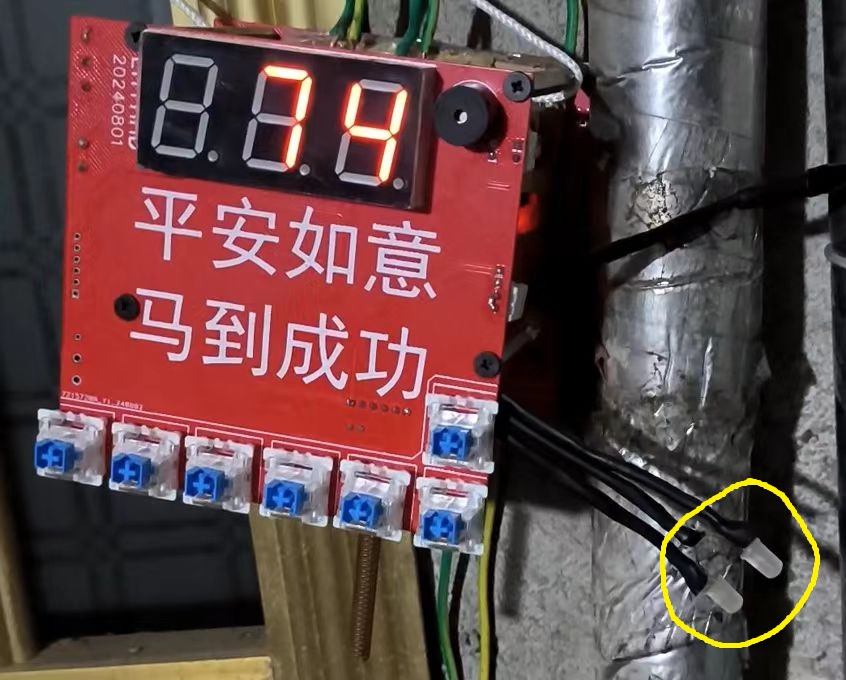
when the water volume of the water tower is lower than 8%, the buzzer will sound an alarm (once every 10 minutes), and the brightness of the digital tube is controlled by the photoresistor.
Regarding the circuit of this board, the initial idea was to make it a universal board for all modules, with each module using this circuit board. Therefore, some explanations were made on the schematic. Later, to perfect the project, this idea was abandoned.
One aspect of the board's circuitry that can be discussed is the button expansion. The schematic is as follows:
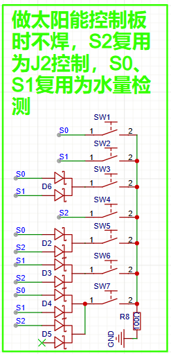
A BAT54C with three GIO pins is used to implement 7 button detections . The original
intention was to use one board for multiple purposes, so GPIO was insufficient, hence
this method. Module usage instructions (for my own reference only, in case I forget): Upon
power-up, the module displays the water level of the stainless steel water tank by default. When the water level drops below 8%, a buzzer sounds every 10 minutes. The six buttons arranged side-by-side, from left to right, are S1, S2, S3, S4, S5, and S6. The single button on the top is S0, which stops the water supply to the stainless steel water tank.
A short press of S1 will cause the digital display to flash "20." Pressing S1 again during this flashing process will start pumping water into the tank until the water level reaches 20%. If no action is taken during the flashing process, the display will return to normal after 5 seconds.
A short press of S2 will cause the digital display to flash "40." Pressing S2 again during this flashing process will start pumping water into the tank until the water level reaches 40%. If no action is taken during this flashing process, the display will return to normal after 5 seconds.
Short presses of S3, S4, S5, and S6 function as above, representing 50%, 70%, 80%, and 100% respectively.
The selected value can be changed by short-pressing other buttons while the digital display is flashing.
The above describes pumping water according to a target water volume. In addition, water can also be pumped according to a target time, such as stopping after 10 minutes. The switch between pumping according to target water volume and pumping according to target time is S6. Press and hold S6 (if the digital display is flashing, a long press has no effect) for 2.2 seconds until the buzzer sounds once, indicating a successful switch. After switching from pumping according to target water volume to pumping according to target time,
briefly press S1. The digital display will flash "10". While the display is flashing, press S1 again to start pumping water into the stainless steel water tower. Pumping will stop after 10 minutes. If no operation is performed during the flashing process, it will return to normal after 5 seconds.
A short press of S2 will cause the digital display to flash "15". Pressing S2 again during this flashing process will start pumping water into the stainless steel water tower, continuing for 15 minutes. If no operation is performed during this flashing process, it will return to normal after 5 seconds.
Short presses of S3, S4, S5, and S6 function as above, representing 20 minutes, 25 minutes, 30 minutes, and 35 minutes respectively.
Similarly, the selected value can be changed by short-pressing other buttons during the flashing display.
Regardless of the pumping method, pumping will immediately stop when the water tower reaches 100% capacity or when there is no water in the tank (the water source for the pump is a float switch that detects water availability).
Press and hold S1 (if the digital display is flashing, pressing and holding has no effect) for 2.2 seconds until the buzzer sounds once. The digital display will then show the water temperature inside the solar water heater. After releasing the button, it will return to its original state (showing the water level in the water tank). If you continue to hold the button for 5 seconds after pressing and holding it for 2.2 seconds, the buzzer will sound again, and then a command will be sent to the solar water heater control module to turn off the electric heating of the solar water heater.
Press and hold S2 (if the digital display is flashing, pressing and holding has no effect) for 2.2 seconds until the buzzer sounds once. The digital display will then show the water level inside the solar water heater. After releasing the button, it will return to its original state (showing the water level in the water tank). If you continue to hold the button for 5 seconds after pressing and holding it for 2.2 seconds, the buzzer will sound again, and then a command will be sent to the solar water heater control module to close the solenoid valve for water inlet to the solar water heater.
This module has two LEDs (circled in the actual picture), one pink and one blue, representing the water inlet status and the electric heating status of the solar water heater, respectively.
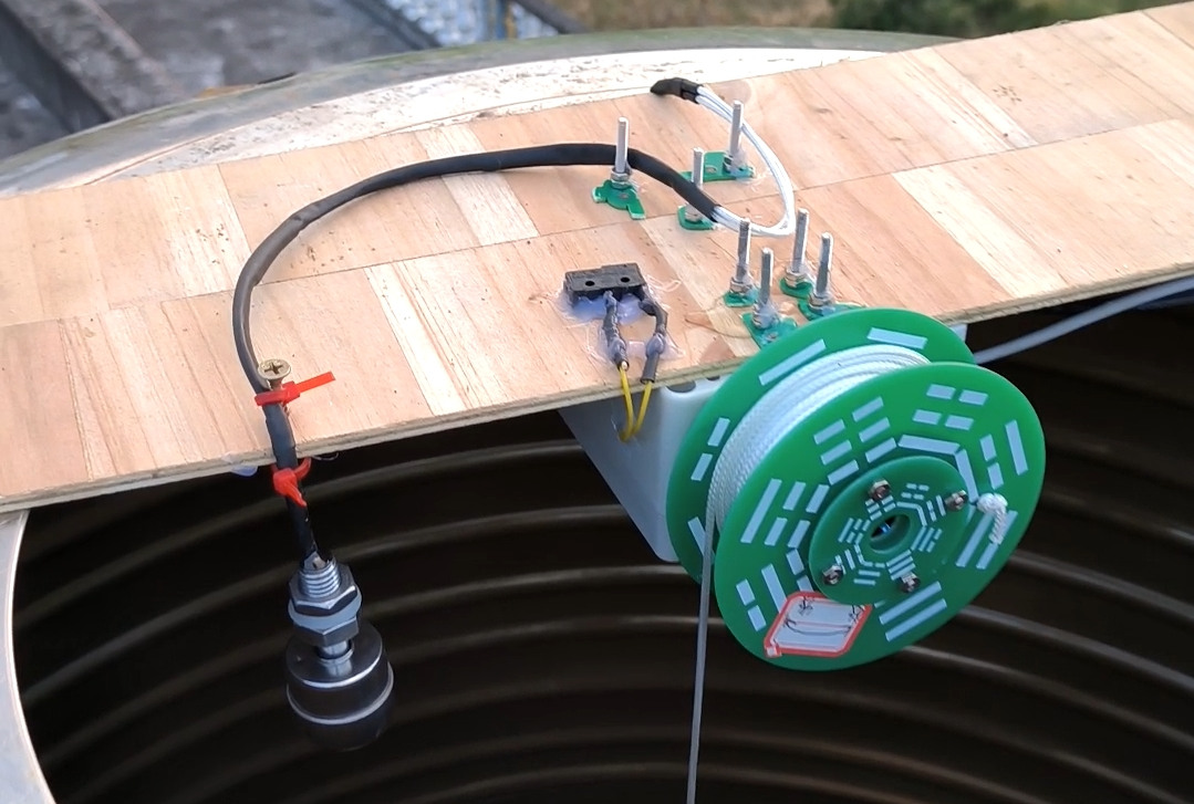
(2). Water Tower Water Quantity Measurement - Motor Schematic

: The schematic is straightforward, consisting of a motor driver, an RS232 converter, an AT24C02 microcontroller, and a single-chip microcomputer.
Water level measurement principle:
1. When water is added, the water level rises, the float switch touches the water, and the encoder motor controls the turntable to retract the float switch upwards until it leaves the water, repeating this cycle.
2. When no water is added, the water volume in the tower decreases with domestic water usage, the water level drops, the float switch leaves the water, and the encoder motor controls the turntable to lower the float switch downwards until it touches the water, repeating this cycle.
3. Once the water level changes, the current encoder value is immediately recorded and saved to the EEPROM. Combined with certain logic (each time power is applied, if the float switch touches the water, it rises to leave the water; if it doesn't touch the water, it falls to touch the water; simultaneously, the encoder value in the EEPROM is read, and the value of the encoder timer register is calculated), it can accurately measure the water level after power failure and upon power-up.
(Bilibili video - Introduction to Water Tower Water Quantity Measurement Principle)
The water tower water level detection module can be used independently in other places without this system. It uses RS232 bus communication with a baud rate of 9600. Upon receiving the following data, it will return the current water level (0~100), module MCU temperature, and fault information:
Receive
0xDD
0xBB
Water supply/use
reset fault
checksum.
Here, "Water supply/use" is 0x2 representing water supply mode and 0x0 representing use mode. "Reset fault" is 0x1 representing a reset sensor fault. A sensor fault occurs when the safety float switch is triggered, but the water level measured by the encoder motor is not 100, which will generate a fault message. The checksum is: ("Water supply/use" + "Reset fault")%256.
The format of the returned data is:
| Return | | | | |
| | --- | --- | --- | --- | --- | --- |
| 0xEE | 0xAA |Water volume (0~100)|Fault information|MCU temperature|Checksum|
The checksum is: ("Water volume" + "Fault information" + "MCU temperature")%256.
The water tower water supply control module needs to be calibrated once before use. The calibration method is as follows:
Turn off the power to the module, manually rotate the rope reel to retract the rope to the position you think represents 100% of the water tower water volume (below the position of the safety float switch), then press and hold the calibration button and turn on the power again. After turning on the power, release the button, and the rope will automatically drop down to the position you think represents 0% of the water tower water volume. Then press the button again to complete the calibration. During the calibration process, it is best not to have water in the water tower. After calibration, power it on again and it will be usable normally.
This is what it looks like after installation.
Bilibili video -- Water tower water volume measurement module working demonstration
Bilibili video -- Water tower water volume measurement module installation
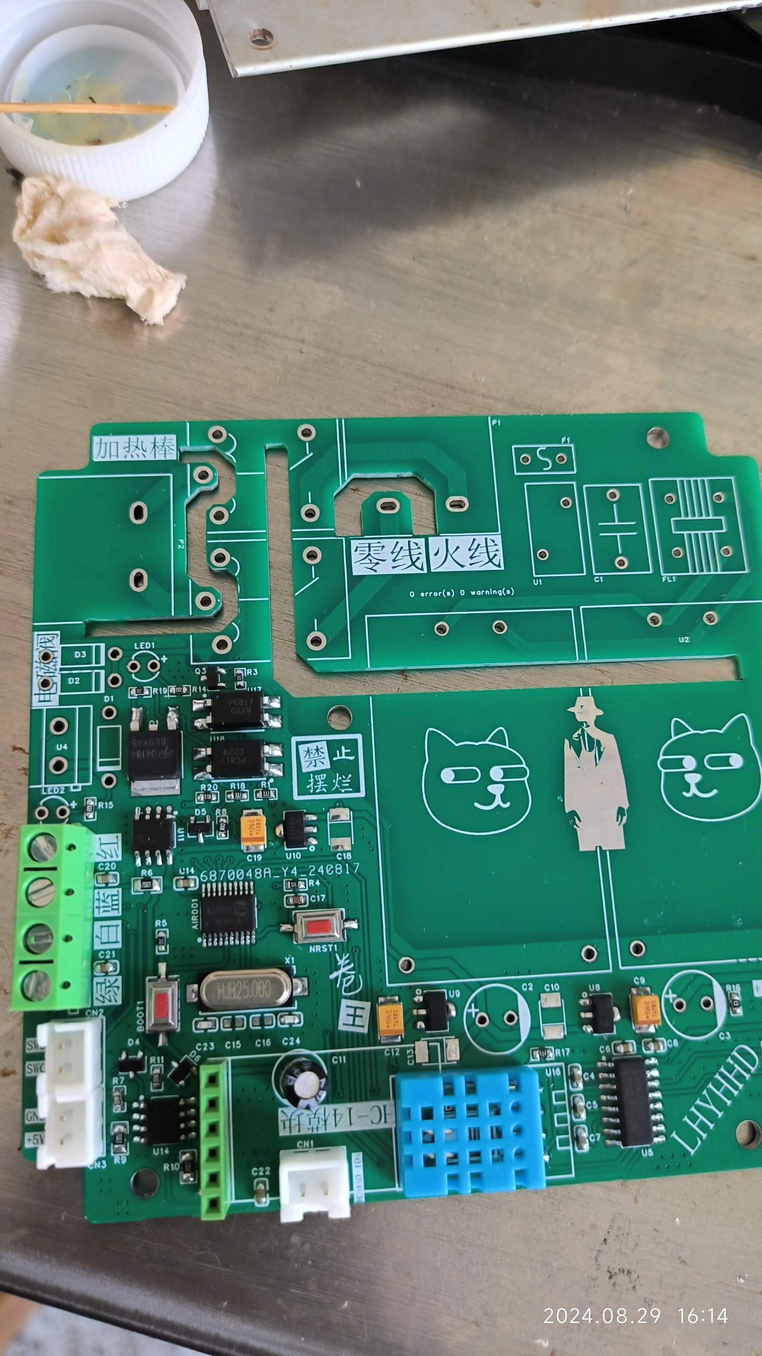
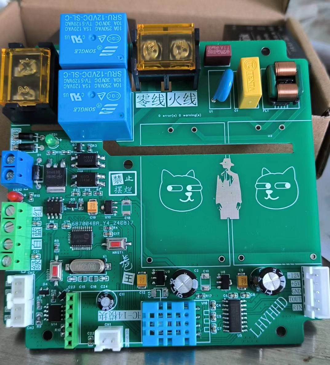
(3).
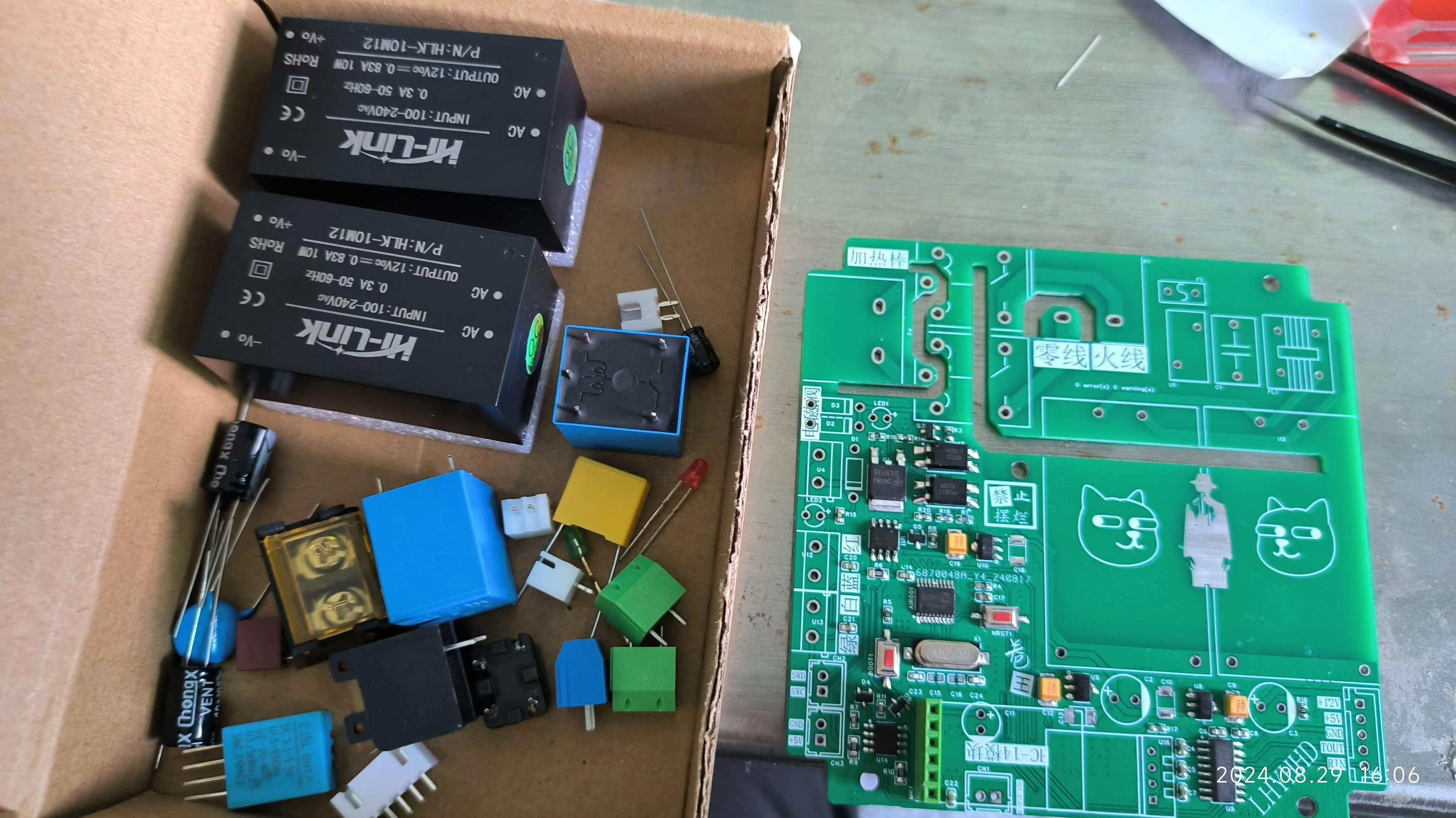
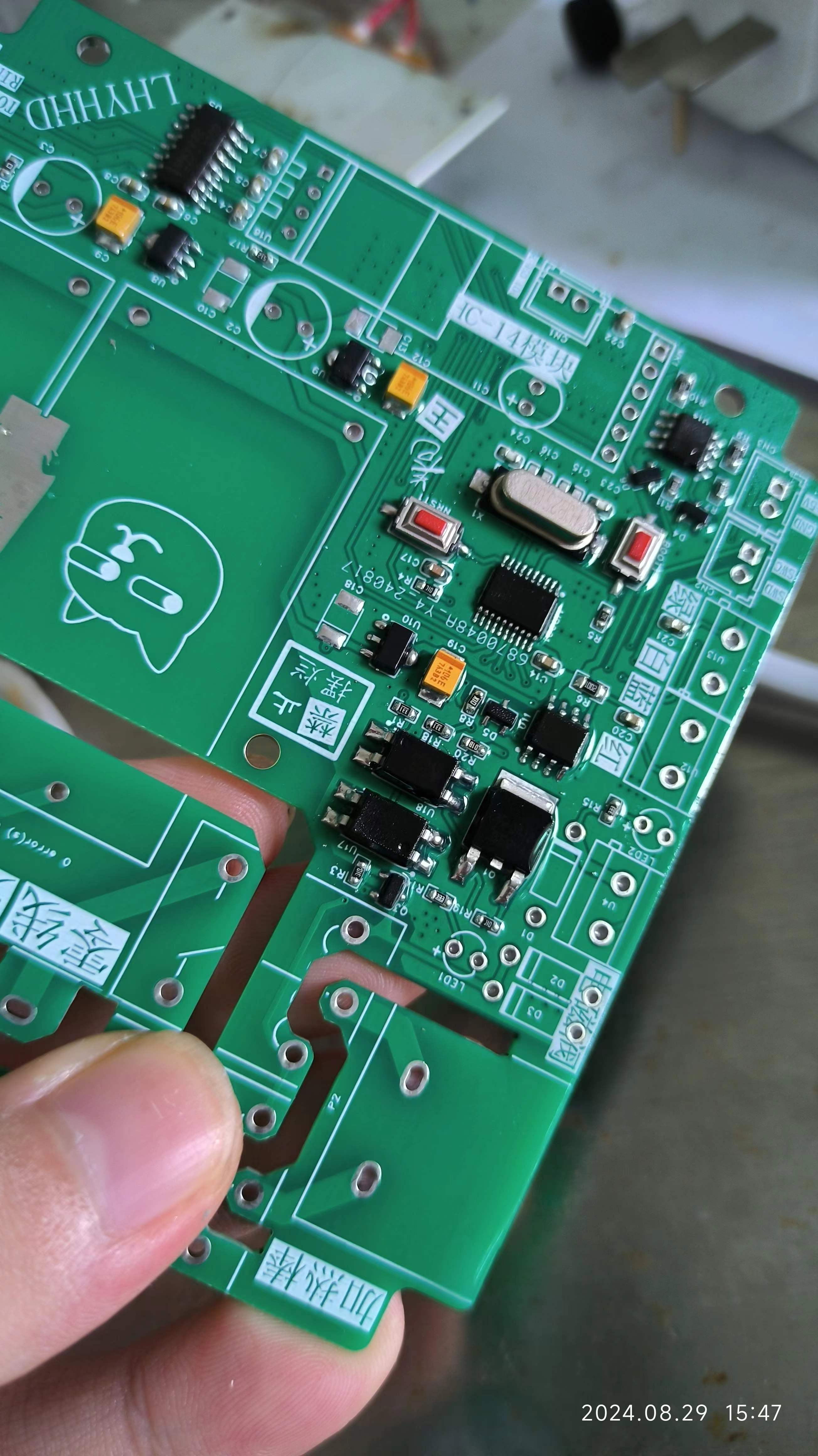
The schematic diagram of the solar water heater control board is too conservative (too many materials are used), mainly reflected in the drive of the solenoid valve and relay and the power supply part; the power supply part uses two Hailingke HLK-10M12 modules, with a total power of up to 20w. It is very cheap to buy it on Taobao (purchase with sign-in coupon).
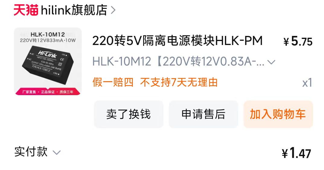
Use ready-made AC-DC power modules, and focus on leaving professional things to professionals, saving time, effort and worry (actually, it is just that I don't know how to use power supply~).
One 12V 10w power supply to the board, and the other 12V 10w power supply to the solenoid valve (3.6w) and RS232, that is, the RS232 interface has a power supply capacity of 6.4w.
12V is supplied to the main controller, LoRa module, and MAX232 via three LDOs.
(Bilibili video - Control Module Introduction)
The difficulty in the solar water heater control module program is driving the four-wire solar water heater sensor. The driving method will be explained later.
(

4) The two discs PCB7 and PCB8
are used to make a winding wheel with the smart car wheel
. (5) The relay module (not used in the project)
consists of a LoRa module (HC-14) and an ESP8266. It is best to power the LoRa module separately.
The circuit part is very simple. The first version of the relay module is used directly, so the second version does not have the relay module circuit.
[ESP12F Relay Module] https://www.bilibili.com/video/BV1xaxjejEZL/?share_source=copy_web&vd_source=68337adbea96c8cef50403a4b2809df6
IV. Software Part
(1). Design of Inter-Module Communication Protocol
In my opinion, for projects with multiple modules communicating, before writing the program (you can write the driver part first), you should first clarify the requirements, figure out what data needs to be transmitted between each module, fully consider the requirements, and then design the communication protocol between each module. Write it into a document or a table, and then start writing the program. At this time, as long as you write the code according to your communication protocol, the efficiency will be much higher, and you can better deal with subsequent problems or add new functions. The screenshot of the communication protocol of this project is as follows, and I will not show the details.

The communication block diagram of this project is as follows
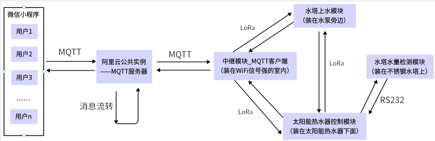
. Note: The relay module, solar water heater control module, and water tower water supply module all transmit data through the nodeless LoRa module. That is, if one party sends data, the other two parties can receive it. This needs to be considered in the program design. In addition, if one party is sending data and the other party also starts sending data, it will cause the LoRa module communication failure. Therefore, this problem should be avoided when designing the communication protocol (two modules cannot send data at the same time at any time). In addition, the transmitted data frame must be equipped with a check code, and important instructions need to be accompanied by an acknowledgment mechanism.
(2). Watchdog
When doing a real project, as long as the microcontroller has a watchdog, it must be used! In applications with more complex logic, it can avoid unexpected logic bugs; at the same time, it can also enhance the product's temperature performance in harsh environments.
(3). The four-wire solar water heater sensor
is essentially a variable resistor. The microcontroller's ADC collects the voltage and converts it into the target value we need. It should be noted that the target voltage after voltage division should be followed by a voltage follower before being input to the microcontroller's ADC. This is because the sensor has a large resistance. If it is directly connected, due to the impedance at the ADC input, it may form a parallel relationship with the external voltage divider resistor, resulting in the actual voltage division value not matching the theoretical value, thus affecting the acquisition accuracy. In addition, for systems that need to operate at high temperatures for a long time, it is best to add a clamping diode to the ADC pin.
Difficulty: How to convert the ADC value into the target value we need; Taobao sellers of this type of sensor basically do not provide useful data, and there is very little information online, so it is almost impossible to find. Therefore, if we want to use this type of sensor, we must measure the data and calibrate it ourselves.
Water level sensor (red and blue lines):
The microcontroller collects the ADC value of the water level sensor at a period of 400ms and outputs it to the serial port assistant. At the same time, the water level sensor is slowly placed in the water until it is completely submerged, and then slowly taken out. Then the data received by the serial port assistant is imported into Excel and a curve of the data is plotted.
After multiple measurements, and by changing the temperature, water quality, and container, all the data curves were obtained, as shown below:
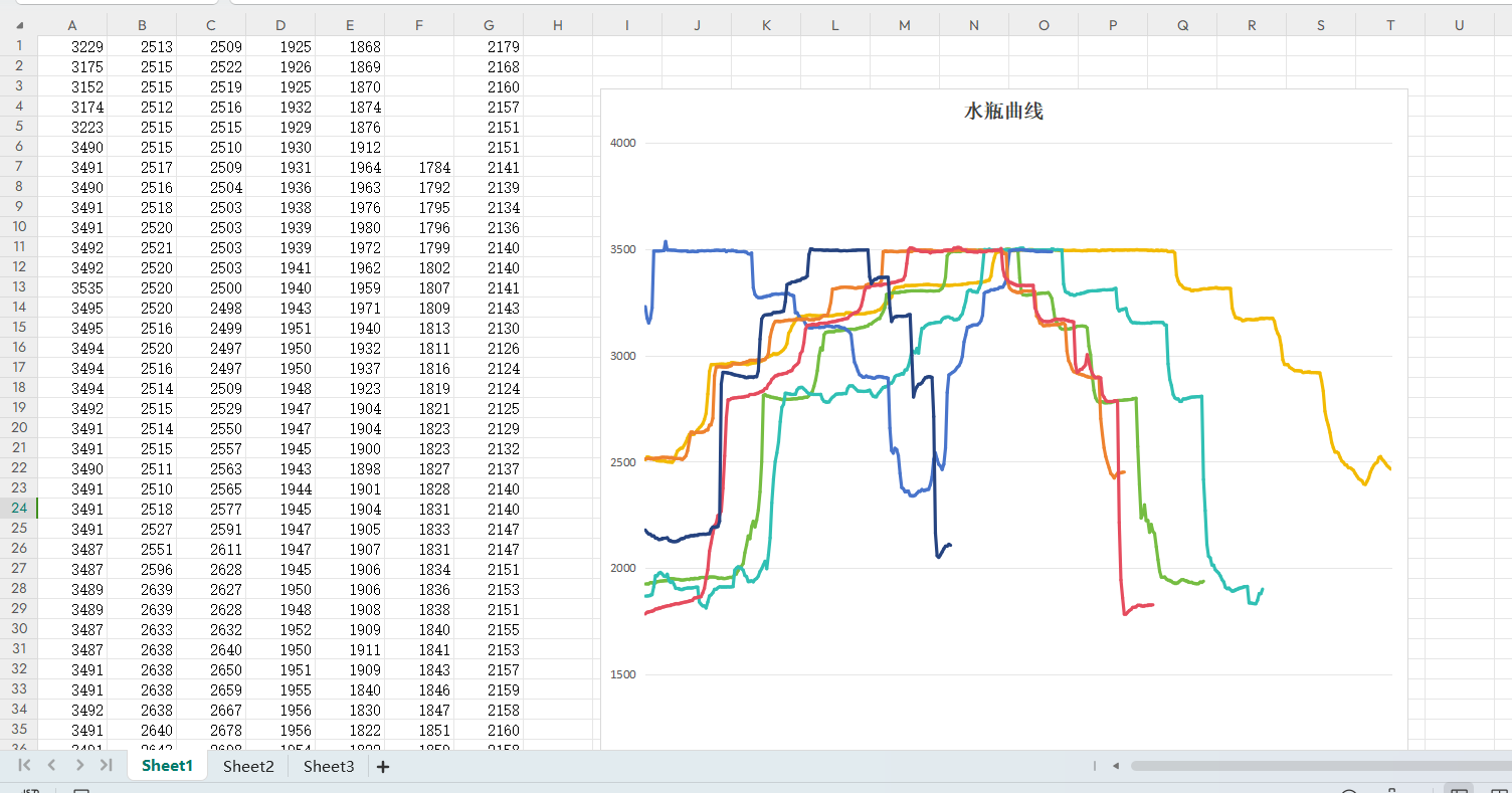
Different colored curves represent different environments. The curves show a five-segment trend under various conditions. We then identified the thresholds between different segments on the curves (each segment must be a different colored curve). By comparing the measured ADC value with these four thresholds (there are only four thresholds for five segments), we can determine the current water level. We define these five segments as 0%, 20%, 50%, 80%, and 100% of the water volume (this is how the original controller defined it). This gives us the water volume in the solar water heater tank.
Water temperature sensor (white-green line):
First, we collected the ADC value of the temperature sensor and observed that it is a positive temperature coefficient resistor. However, the resistance value does not conform to common thermistors such as PT100 and PT1000. Fortunately, our requirements for water temperature accuracy are not high, so we can use a sensor that can accurately measure temperature to calibrate this water temperature sensor. The temperature sensor I used here for calibration is a 10K B3950. NTC thermistor (negative temperature coefficient);
First, put the water temperature sensor and NTC thermistor into the electric kettle. Then, the microcontroller outputs the temperature measured by the NTC thermistor and the original ADC value of the water temperature sensor collected by the ADC through the serial port, as shown below:

The first data is the temperature measured by the NTC thermistor, the second is the original ADC value of the water temperature sensor, and the third is the ADC value of the water volume sensor.
Then start heating the electric kettle until the NTC thermistor outputs 76 degrees. In this way, we get the original ADC value of the water temperature sensor at different temperatures. Then import these two sets of values into a linear regression analysis website, as shown below:
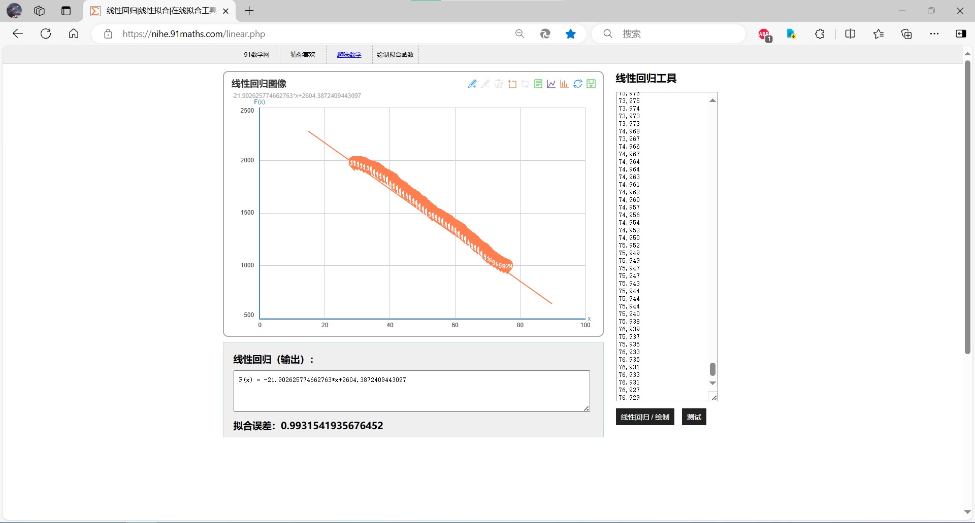
As can be seen from the figure, all the data basically fall on a straight line. The data is very linear. Based on the linear function calculated by the website, we can calculate the approximate real temperature using the original ADC value of the water temperature sensor. The calculation relationship is as follows

(4). Data storage
does not use a database. The appointment event, the historical water temperature of the last 24 hours, the historical water volume of the last 24 hours, the running mode, the threshold temperature, and the execution advance data are all stored in the relay module; the user information is stored in the code of the WeChat mini program constant (only 7 users).
V. WeChat Mini
Program Name: That Year, That Month, That Day 9
Don't ask why I chose this name; all the names related to solar water heaters are already taken.
The mini program requires a key verification before it can control my home devices. Why use this primitive verification method instead of one-click verification of user information using a phone number? Because WeChat's official review process is very strict regarding anything involving user privacy. As an individual developer with no qualifications to guarantee this, I shouldn't even think about obtaining users' phone numbers. Some might ask, why is verification required? Because WeChat mini programs are open; anyone can use them. If verification wasn't needed, wouldn't everyone be able to control my home devices at will?
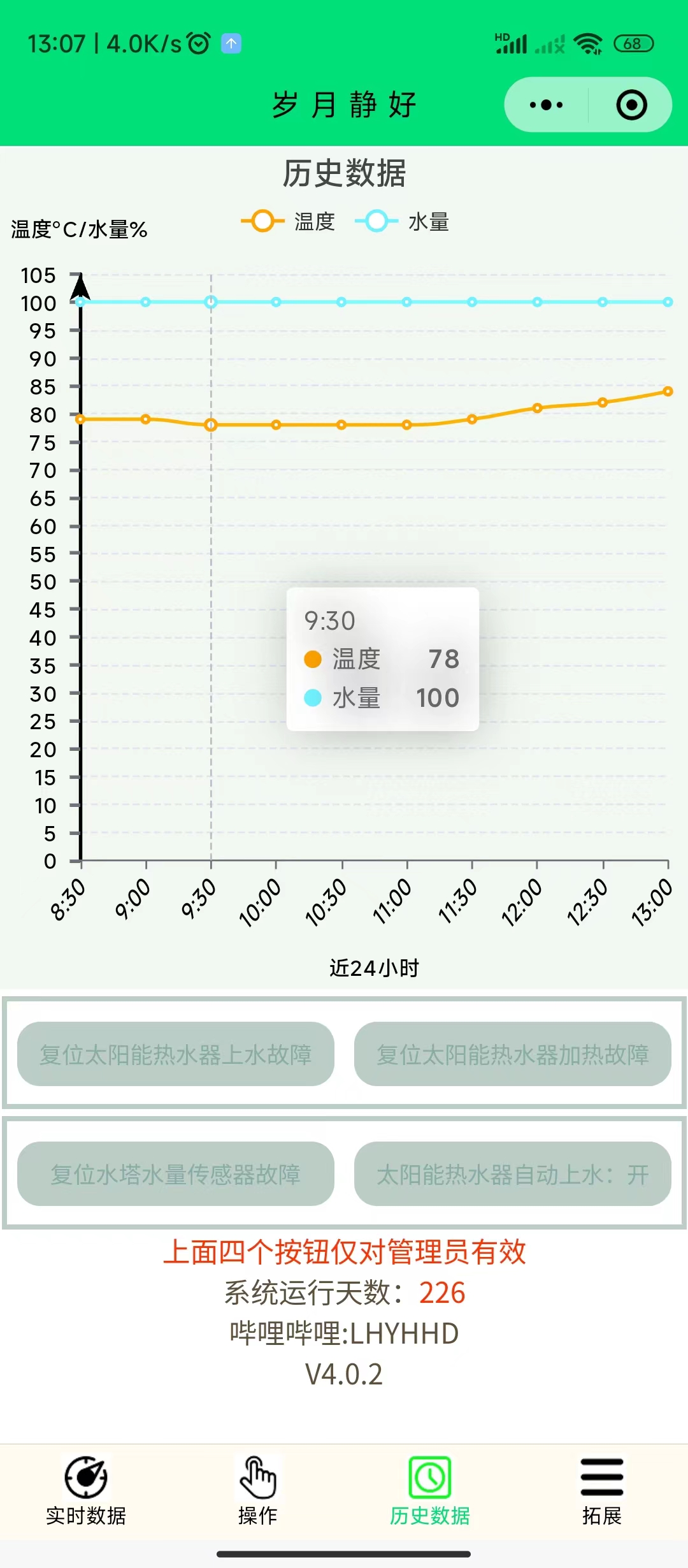
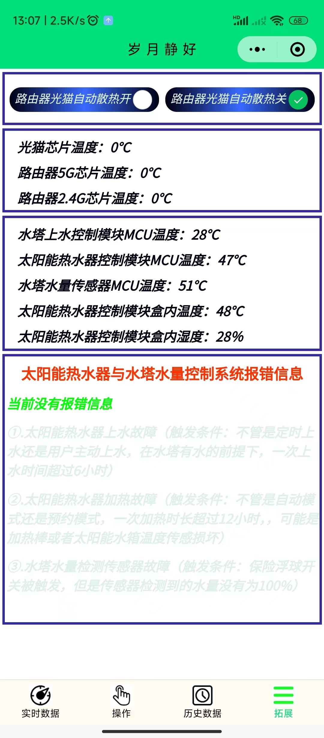
The WeChat mini program has four
operation pages:
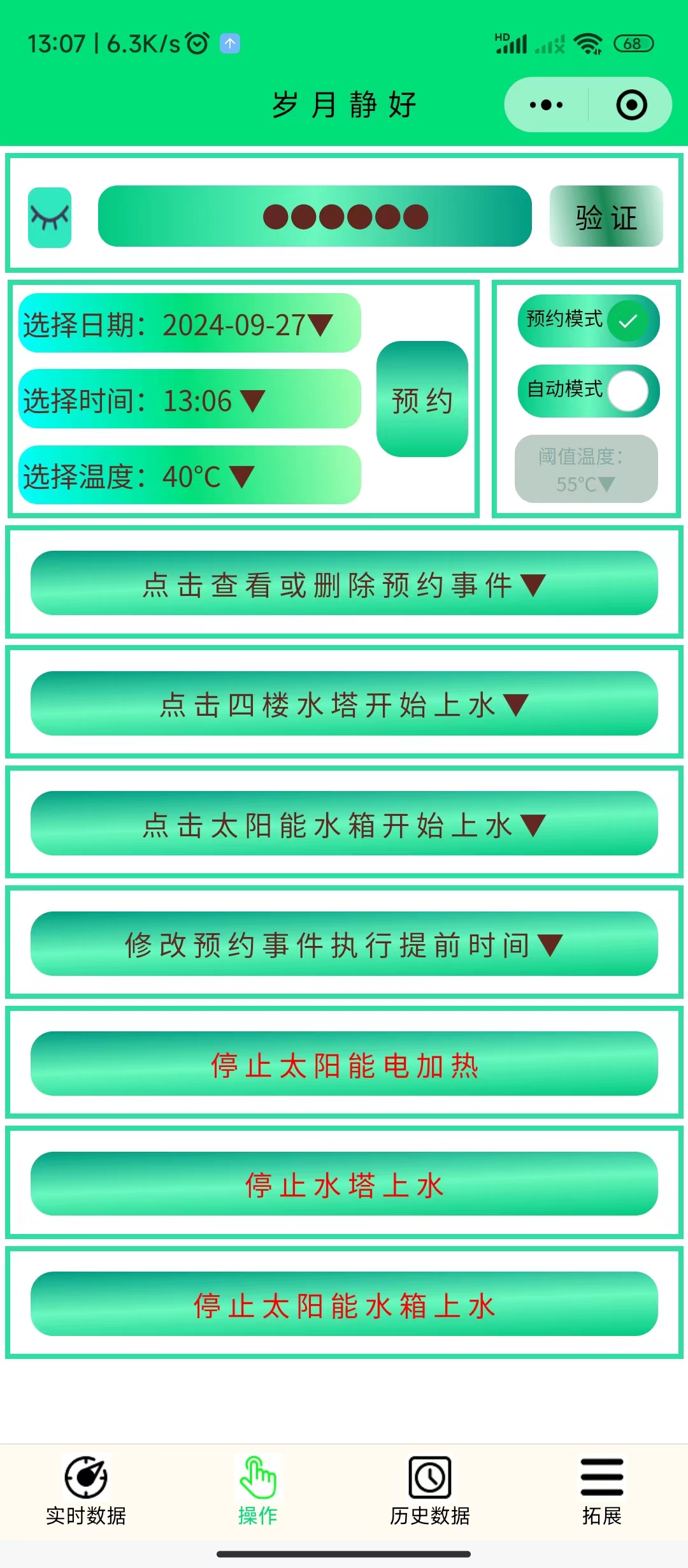
Real-time data page,

Historical data page, and
Extended page.
At first glance, it may seem complicated, but most functions and data do not require attention. Only two require human intervention: one is to add water to the stainless steel water tower, and the other is to schedule events. The solar water tank will automatically add water (when the water level in the stainless steel water tower is greater than 8%, it will automatically add water to 100% at 1:00 AM every day). The solar electric heating will decide whether to turn on the electric heating based on the scheduled events, real-time temperature, and execution advance.
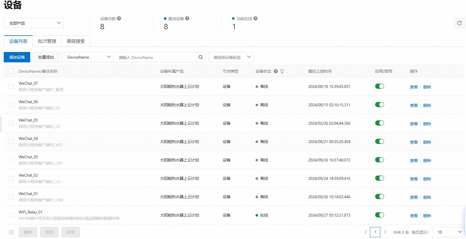
Different users use different keys for verification. The WeChat Mini Program distinguishes different users based on the entered key. Each user corresponds to a device in the Alibaba Cloud public instance, as shown below:
The viewing method for appointment events is as follows:
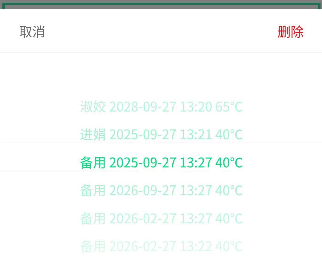
An appointment event consists of the user name + specific date and time + water temperature. Each appointment event is automatically deleted after execution. A maximum of 50 appointment events can exist. Users cannot delete other users' appointment events. When the Mini Program adds or deletes an appointment event, the data format sent to the relay module is as follows:

The format of the appointment data reported by the relay module to the Mini Program client is as follows:
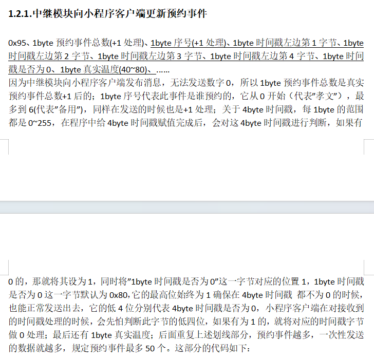
The data source code of the appointment data reported by the relay module to the Mini Program client is as follows:
void yy_event_updata(){
mqtt_tbuff[0] = 0x95;//The appointment event is updated
mqtt_tbuff[1] = yy_event_num+1;//Total number of events, must be +1 for processing!
uint8_t con = 0;
for(uint8_t i=0;i<50;i++){
if(yy_event_list[i].xh!=0xFA){//Indicates this position is a valid reservation event
mqtt_tbuff[2+con*7] = yy_event_list[i].xh+1;//Increment the sequence number by 1
mqtt_tbuff[4+con*7] = ((yy_event_list[i].time&0xFF000000)>>24);//The first byte from the left of the timestamp
mqtt_tbuff[5+con*7] = ((yy_event_list[i].time&0xFF0000)>>16);//The second byte from the left of the timestamp
mqtt_tbuff[6+con*7] = ((yy_event_list[i].time&0xFF00)>>8);//The 3rd byte from the left of the timestamp
mqtt_tbuff[7+con*7] = (yy_event_list[i].time&0xFF);//The 4th byte from the left of the timestamp
//Change the +1 processing, because for the timestamp, it is possible that a byte is exactly 255, and +1 will just return to 0. This +1 method cannot solve the problem, so add a separate byte to record whether it is 0.
The lower 4 bits of this byte record whether the four bytes of the timestamp are 0, and the highest bit 1 is to ensure that this byte is not 0
mqtt_tbuff[3+con*7] = 0x80;//Ensure that this byte is not 0
for(uint8_t t=0;t<4;t++)//Traverse the four timestamp bytes and see if there is a byte that is 0
if(mqtt_tbuff[4+con*7 + t]==0){
// Ensure the sent value is not 0. This byte of timestamp data is no longer needed. The mini-program detects that the t-th bit on the right of `mqtt_tbuff[3+con*7]` is 1, so it directly treats this byte as 0.
`mqtt_tbuff[4+con*7 + t]+=1;
` `mqtt_tbuff[3+con*7] += 0x01<<(3-t);` // Tell the mini-program that this byte of timestamp data is 0.
} `
mqtt_tbuff[8+con*7] = yy_event_list[i].temp;` // This is the actual temperature, ranging from 40 to 80, so no need to add 1. `
con++;
`
} `
mqtt_tbuff[8+con*6] = 0;` // Add 0 at the end.
`logln(con);` `logln(yy_event_num);` `
pubMQTTmsg((char*)mqtt_tbuff);`
The source code for parsing the appointment event sent by the relay module in the mini program client is as follows: }
else if(payload[0]==0x95){//appointment event
var str = ''//'Xuhua 2024-02-13 10:00 40℃'
this.globalData.yuyueshijian_data=[]//clear the original appointment event
for(i=0;i<(payload[1]-1);i++){//total number of events, which was sent by +1 over there, to prevent 0
str=this.globalData.u_n_font[payload[i*7+2]-1]//the sequence number was also sent by +1
let sjc = 0;
if((payload[i*7+3]&(0x08))!=0)sjc=0;
else sjc=payload[i*7+4]<<24;
if ((payload[i*7+3]&(0x04))!=0)sjc+=0;
else sjc+=payload[i*7+5]<<16;
if ((payload[i*7+3]&(0x02))!=0)sjc+=0;
else sjc+=payload[i*7+6]<<8
if ((payload[i*7+3]&(0x01))!=0)sjc+=0;
else sjc+=payload[i*7+7];
let dt = new Date(sjc*1000)//The unit passed in here should be ms
if ((dt.getMonth()+1)<10)
str +=' '+dt.getFullYear().toString()+'-0'+(dt.getMonth()+1).toString()+'-'
else
str +=' '+dt.getFullYear().toString()+'-'+(dt.getMonth()+1).toString()+'-'
if(dt.getDate()<10)str += '0'+dt.getDate().toString()
else str += dt.getDate().toString()
if(dt.getHours()<10)str +=' 0'+dt.getHours().toString()+':'
else str +=' ' +dt.getHours().toString()+':'
if(dt.getMinutes()<10)str += '0'+dt.getMinutes().toString()
else str += dt.getMinutes().toString()
str += ' '+payload[i*7+8]+'℃'//This is the real temperature, ranging from 40 to 80
this.globalData.yuyueshijian_data=this.globalData.yuyueshijian_data.concat(str)
}
if(this.globalData.esp_ack_enable)this.globalData.esp_ack = 2 // Relay execution complete response
console.log("Received appointment event")
}
The relay module reports appointment events, and the WeChat mini program parses appointment events according to the specified protocol. Therefore, as long as the communication protocol is designed well, the code part is very simple.
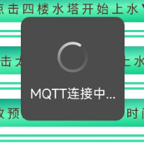
In WeChat Mini Programs, during user verification, if successful, the following messages will appear sequentially: "Verification successful" -> "MQTT connection in progress..." -> "Waiting for relay response" -> "Data acquisition successful". If the network is stable, the entire process should take no more than 3 seconds.
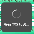

If no data is received from the relay module, a dialog box will pop up to prompt the user.

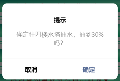
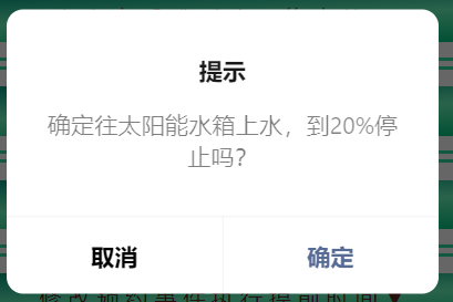
All operations will have dialog boxes to ask the user again whether they are sure they want to execute the operation


 II. USB Serial Port Data Communication :
  III. Four-Channel Analog Data Acquisition
 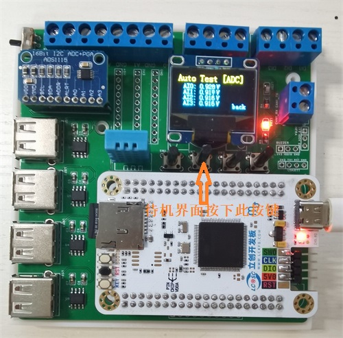 IV: Digital Input Acquisition and Digital Output Control.
 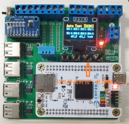 V: Automated Test Recipe File Reading.
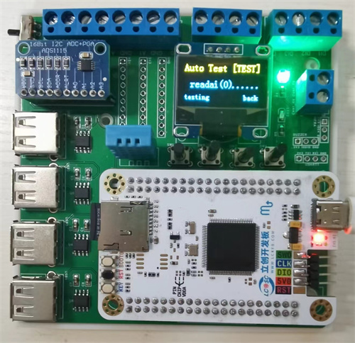
 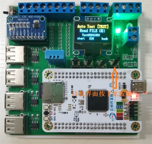 Six: Automated Test Execution.
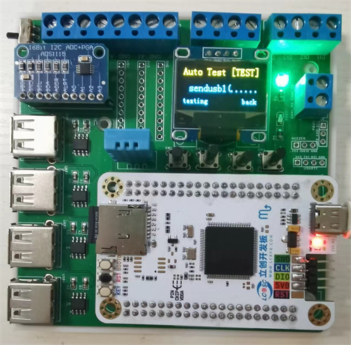
 After the test sequence in the recipe is completed, the screen displays "Test Finish." Pressing the fourth button (back) returns to the standby screen, as shown in the image below.
 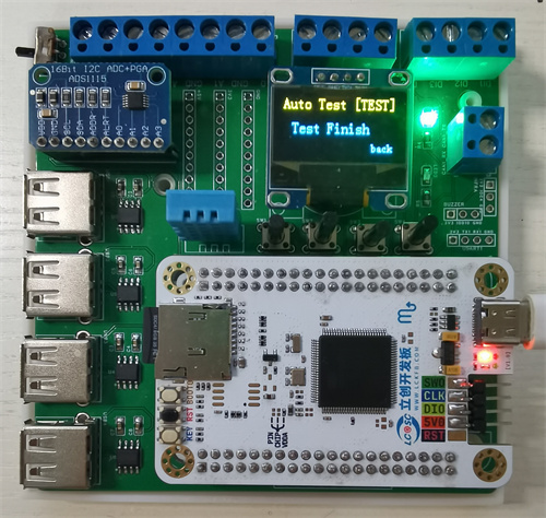 Seven: SD Card Mode
 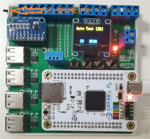 Project Parameters
 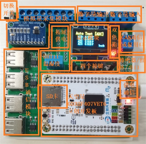 The Skystar development board is used as the main controller to read the Recipe.txt recipe file stored in the SD card, and then controls the USB serial port, ADC acquisition module, digital input/output port, DHT11 temperature and humidity sensor, buttons and display screen in sequence.
 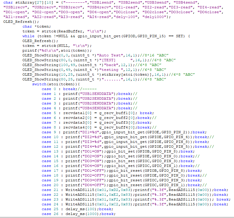 The automated testing machine expansion board in this project can run test sequences independently of a computer. However, when conditions permit, this hardware can also be connected to a computer via USB cable for necessary monitoring, data reading, and test recipe generation via a host computer.
  The image above shows the Test Monitoring tab. During testing, the expansion board sends the current test sequence number to the serial port, so the current test progress can be determined by parsing the sequence number.
  The image above also shows the Host Computer Data Reading tab. This page can read test data and test recipe information from the SD card. The
 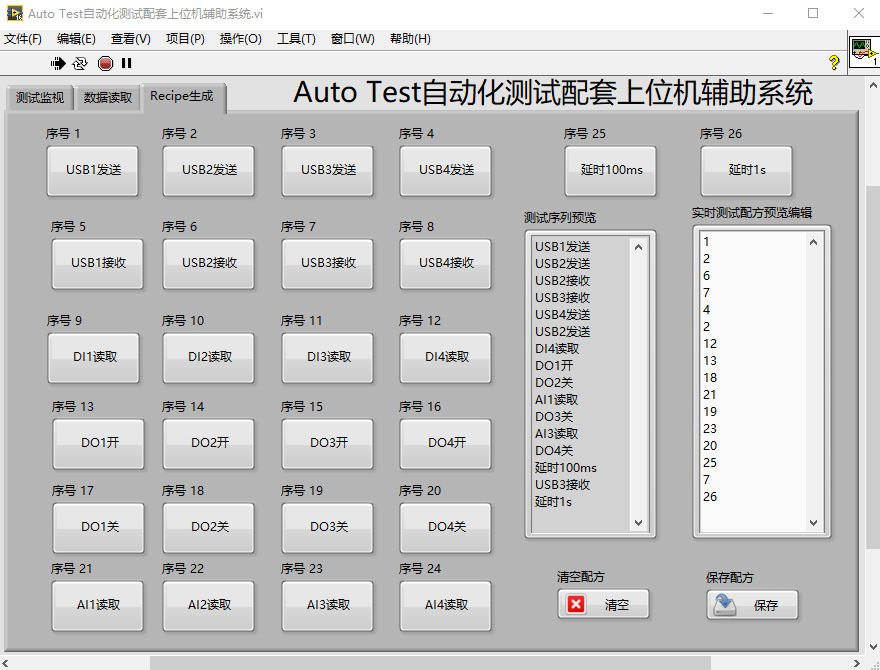 image above shows the Test Recipe File Generation page. This page has multiple test buttons. Pressing the corresponding button generates the corresponding sequence in the string display control. In the real-time test recipe preview and editing, the actual recipe file content can be modified, and the string control content can be cleared or saved as a Recipe.txt file in the current folder.
 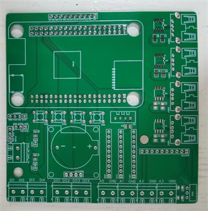 Back:
Back:  During soldering, first solder the surface-mount components, such as LEDs, resistors, CH340N capacitors, and capacitors. Then solder the headers, buttons, USB sockets, battery holders, and other connectors. Headers are used here for easy removal of the development board from the board. Finally, solder the development board's headers to the display screen and ADS1115 module, inserting them into the corresponding headers.
 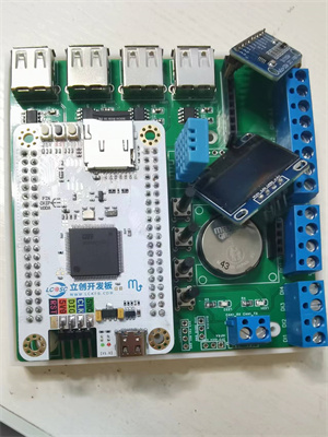 In addition, this project also designed a corresponding 3D hardware casing, using a top and bottom casing. The actual casing image is shown below:
 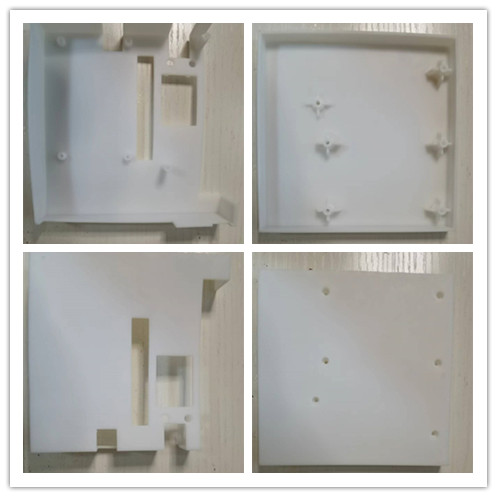 [Image of the actual casing] [
 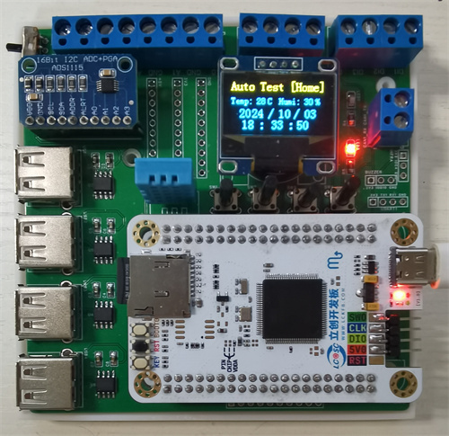 Finished product appearance after casing assembly:
  Finally, this project inevitably has some problems; please leave comments for discussion. Thank you.
 video demonstration
  two MSM261S4030H0R microphones
 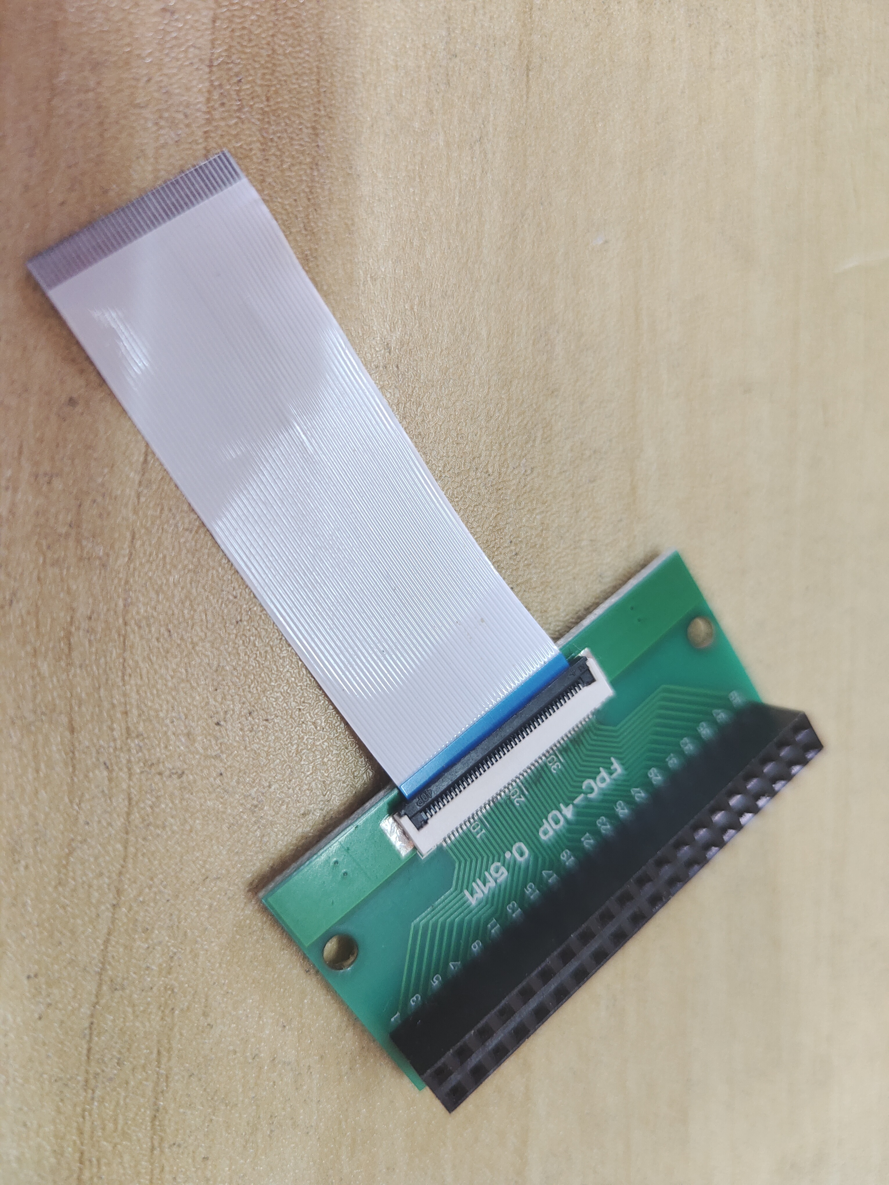 software code
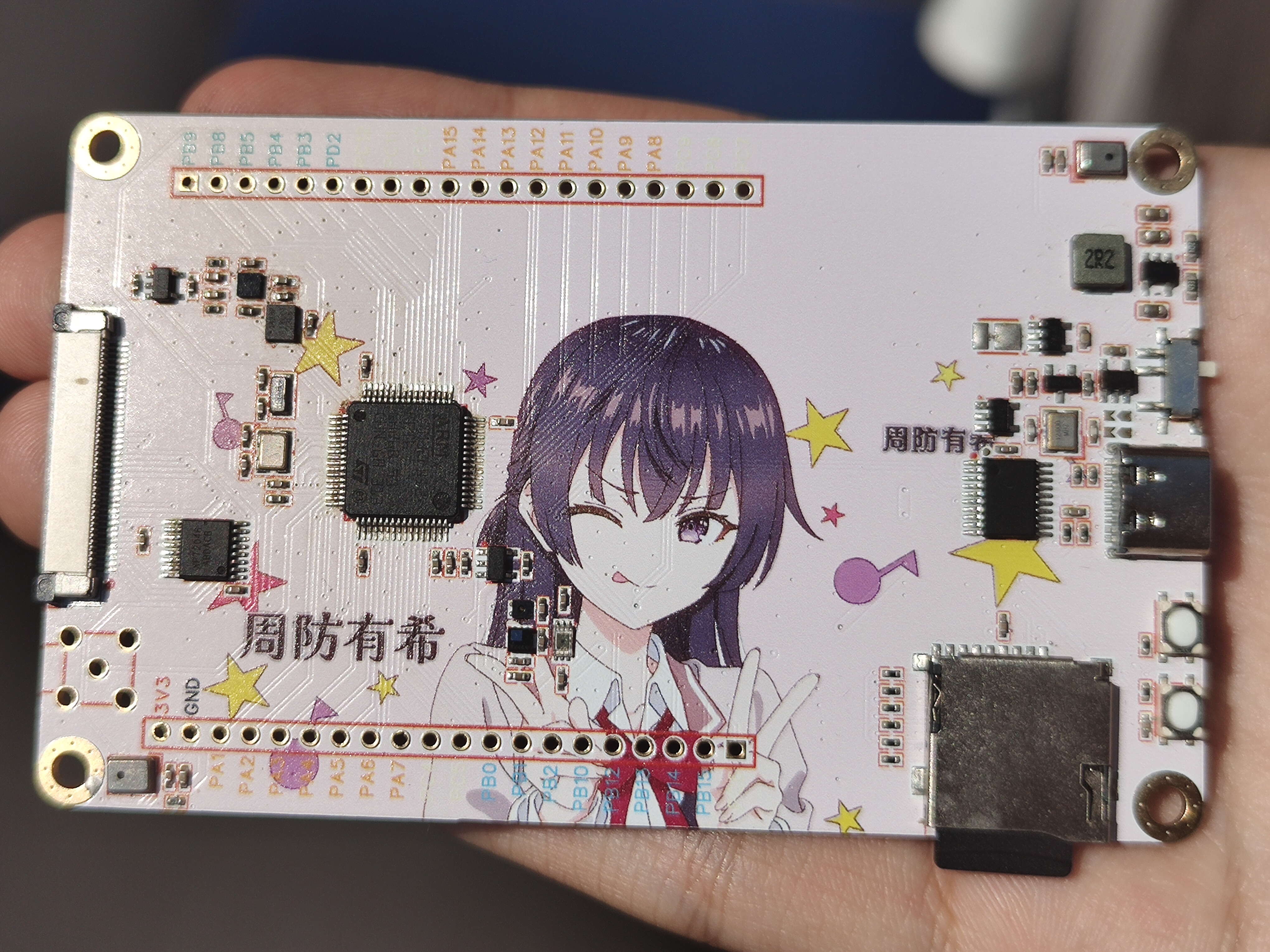


 京公网安备 11010802033920号

 HN29WB800R-10


