Project Overview:
In the automatic control industry, computers or industrial PCs are generally used as host computers for instrument testing and measurement control, such as digital input acquisition and output control, analog input acquisition, and USB communication. However, for simple testing and automatic control, using computers or industrial PCs for measurement and control is overkill and not conducive to cost reduction. To fully utilize hardware performance, the SkyStar system development board's GD32F407, a domestically produced microcontroller core, fully meets the needs of ordinary instrument automation testing. Based on this, the author developed an automated testing machine expansion board based on SkyStar and cleverly utilized the switch syntax in C language to develop the hardware and software for this project. LabVIEW was used for auxiliary test process monitoring, data viewing, and recipe file generation. This project is the author's original work and has not been published in any other projects. If you reprint or reference this project, please be sure to include the website link of this project. Thank you.
Project Functions:
The hardware in this project has the following individual or comprehensive testing functions, detailed below:
I. RTC Date and Time and Real-time Temperature and Humidity Monitoring Standby Display:
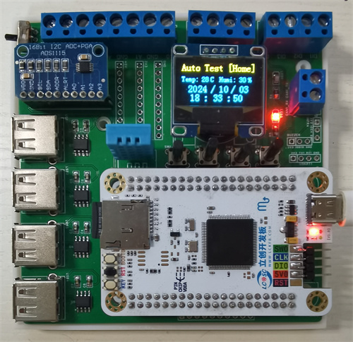
The hardware is powered via the USB interface of the SkyStar development board. When the upper left switch is in the bottom position, it is in standby mode. The red light on the right side of the screen is on, and the green light is off, indicating non-automatic testing. The upper right corner of the program screen displays "[Home]". The temperature and humidity data collected by the hardware via DHT11 and the date and time data from the RTC are displayed on the screen in real time, as shown in the figure below.

II. USB Serial Port Data Communication :
When the hardware is powered on and in standby mode, pressing the first button at the bottom of the screen will display the data received via USB in real time, with "[USB]" displayed in the upper right corner of the screen. Pressing the first button again ("send") will send a test string to the USB serial port. Pressing the fourth button ("back") will return to the standby interface, as shown in the figure below.

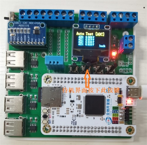
III. Four-Channel Analog Data Acquisition
: When the hardware is powered on and in standby mode, pressing the second button at the bottom of the screen will display the data from the four channels acquired by the ADS1115 module in real time, with "[ADC]" displayed in the upper right corner of the screen. Pressing the fourth button (back) again returns to the standby screen, as shown in the image below.
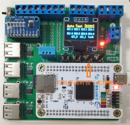
IV: Digital Input Acquisition and Digital Output Control.
When the hardware is powered on and in standby mode, pressing the third button at the bottom of the screen displays the high/low level status data of the four digital inputs and four digital outputs in real time. 0 represents low level, and 1 represents high level. The upper right corner of the screen displays [DIDO]. Pressing the second button (all_0) again sets all four digital outputs (DO) to low level (0). Pressing the third button (all_1) again sets all four digital outputs (DO) to high level (1). Pressing the fourth button (back) again returns to the standby screen, as shown in the image below.
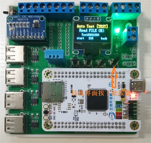
V: Automated Test Recipe File Reading.
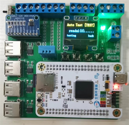
When the hardware is powered on and in standby mode, pressing the fourth button at the bottom of the screen enters the automated test interface. The red light on the right side of the screen goes out, and the green light turns on, indicating that the automated test program has started. The upper right corner of the screen displays [TEST]. The system will then read the recipe file from the SD card. If the reading is successful, it displays "Read FILE OK!" and displays the first line of the recipe file (test date and time information) in the middle of the screen. The number in the center of the bottom of the screen displays the number of bytes read from the recipe file. Pressing the first button (start) again initiates automated testing, and pressing the fourth button (back) returns to the standby screen, as shown in the image below.
Six: Automated Test Execution.
In the automated test interface, pressing the first button (start) initiates the test process. The screen displays the name of the read test item. Hardware acquisition and control are performed sequentially according to the test sequence. Acquisition and control items include USB transceiver communication, analog AI acquisition, digital input acquisition, digital output control, and test delay. The real-time test interface is shown in the image below.
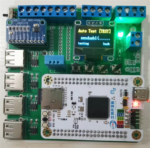
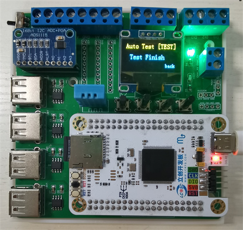
After the test sequence in the recipe is completed, the screen displays "Test Finish." Pressing the fourth button (back) returns to the standby screen, as shown in the image below.
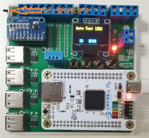
Seven: SD Card Mode
. When the switch in the upper left corner of the hardware is moved to the top, it enters SD mode. In this mode, the Skystar development board releases control of the SD card, allowing normal removal of the SD/TF card for data reading and recipe file writing. The SD mode interface is shown in the following figure:
Project Parameters
The hardware parameters of this project are as follows:
The development board is a Skystar LCSC development board with an SD card slot. The specific chip on the board is the domestic GD32F407VET6 chip;
The USB serial port chip is CH340N, which converts the microcontroller's TTL signal into a USB signal for communication with equipment, instruments, or computers;
The ADC channel uses the ADS1115 four-channel analog acquisition module, which has 16-bit precision and IIC communication features;
The DIDO digital input/output uses the microcontroller's built-in GPIO ports, with four digital inputs and four digital outputs;
Temperature and humidity acquisition uses the DHT11 module; The hardware display uses a 0.96-inch dual-color OLED screen with IIC communication;
2.54mm pin headers are reserved for CAN communication, buzzer, infrared communication, and power supply for future expansion.
Principle Analysis (Hardware Division)
The hardware module area division of this project is as follows:
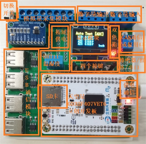
The Skystar development board is used as the main controller to read the Recipe.txt recipe file stored in the SD card, and then controls the USB serial port, ADC acquisition module, digital input/output port, DHT11 temperature and humidity sensor, buttons and display screen in sequence.
The development board can control test and measurement hardware such as programmable power supplies, stepper motor controllers, and power meter data acquisition via USB serial port. It sends acquisition control commands to the USB serial port and records and parses the data returned from the serial port.
The ADC acquisition module uses the readily available ADS1115 high-precision 16-bit analog acquisition module, configured with single-ended four-channel acquisition and IIC communication. Acquisition channels are switched by sending commands. The
digital input/output ports use the GPIO ports provided by the development board, configured with four digital inputs and four digital outputs. The digital input ports can monitor switch closure signals, and the digital outputs can control actuators controlled by high and low levels, such as relays and buzzers.
The DHT11 temperature and humidity sensor uses single-wire communication; note that the DATA line needs to be pulled up.
Buttons and switches determine whether they are pressed by monitoring the port level; software delay is used to confirm button presses and reduce input signal jitter.
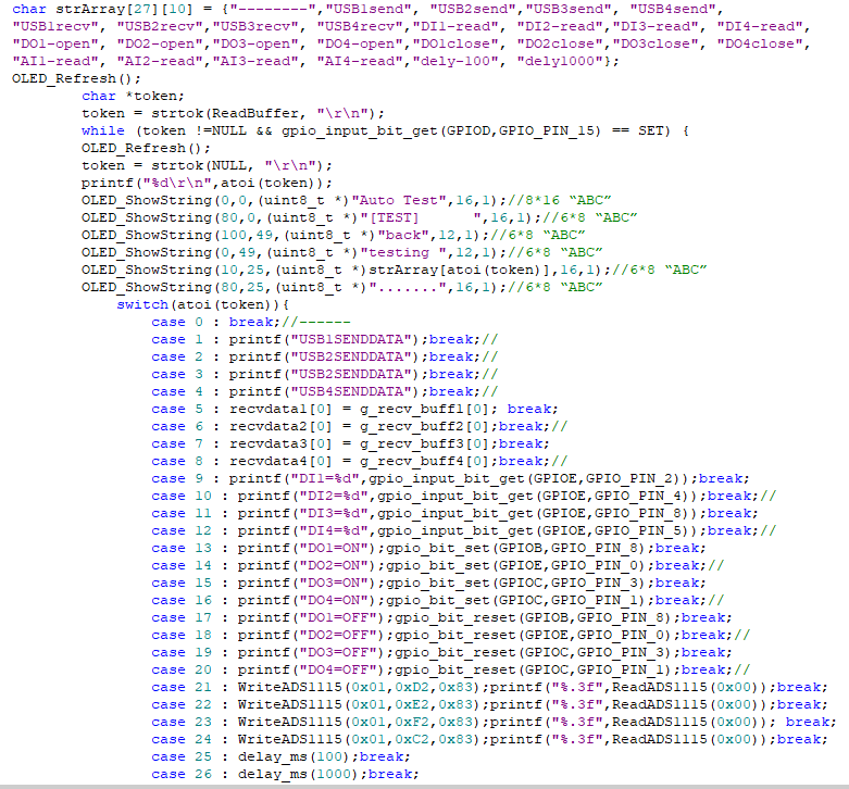
The display uses a 0.96-inch dual-color screen, with yellow text for the title bar and blue text for the content bar, making interaction and display convenient and aesthetically pleasing. The core code of the lower-level
machine
in this project is shown in the figure below. Each test corresponds to a numerical sequence number. After the SD card reads the recipe file, it splits the test sequence number by line, and then uses the array index of the pre-compiled test sequence to find the corresponding test sequence number. The switch conditional case branches are used to execute the test control content of the specified test sequence number in sequence. Currently, 27 sequences are specified. Sequence number 0 is a separator, generally used at the beginning and end or as a dividing line for dividing the test into several parts. The actual content is not executed: case1 to case8 are the send and receive instructions for the four USB serial ports, respectively; case9 to case20 are the four digital input acquisition instructions, the four digital output level setting instructions, and the four digital output level setting instructions; case21 to case24 are the four analog channel acquisition instructions; case25 and case26 are the instructions with delays of 100ms and 1000ms, respectively, used to perform necessary hardware test pauses during the test.
The automated testing machine expansion board in this project can run test sequences independently of a computer. However, when conditions permit, this hardware can also be connected to a computer via USB cable for necessary monitoring, data reading, and test recipe generation via a host computer.
Host Computer Auxiliary System Interface:

The image above shows the Test Monitoring tab. During testing, the expansion board sends the current test sequence number to the serial port, so the current test progress can be determined by parsing the sequence number.

The image above also shows the Host Computer Data Reading tab. This page can read test data and test recipe information from the SD card. The
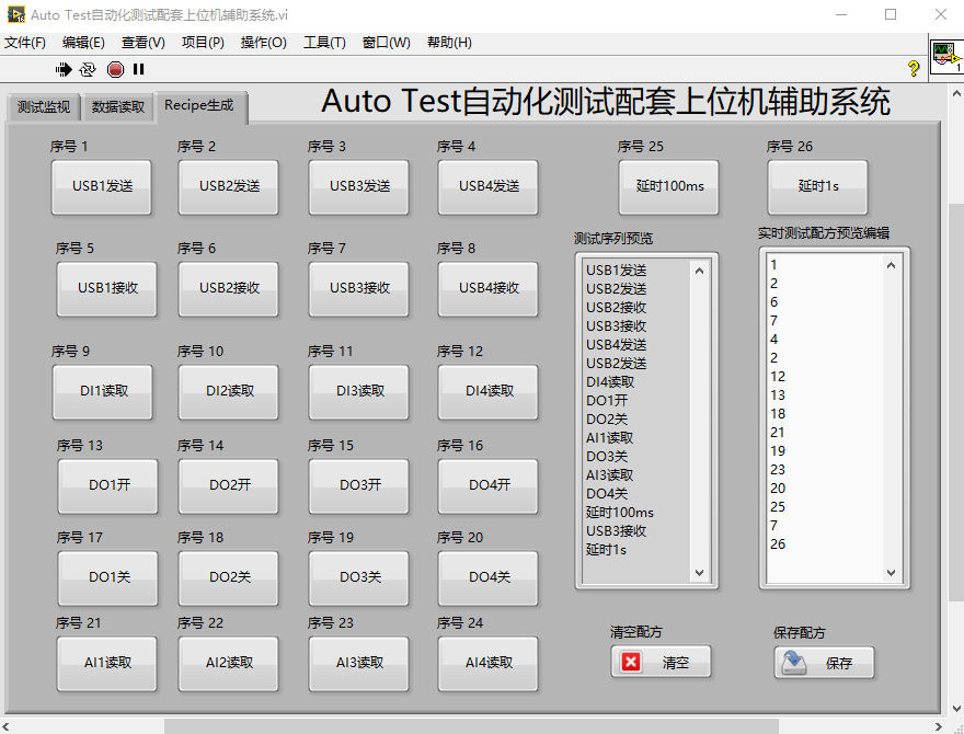
image above shows the Test Recipe File Generation page. This page has multiple test buttons. Pressing the corresponding button generates the corresponding sequence in the string display control. In the real-time test recipe preview and editing, the actual recipe file content can be modified, and the string control content can be cleared or saved as a Recipe.txt file in the current folder.
The following are links to some of the code references for this project:
SD Card Read/Write:
GD32+FATFS+SDIO; OLED Video Playback Porting Troubleshooting (Bad); Apple
ADS1115 Analog Input Acquisition:
ADS1115 Multiplexer Module Porting Document
; DHT11 Temperature and Humidity Acquisition:
DHT11 Temperature and Humidity Sensor Module Porting Document;
0.96-inch IIC Screen Display:
0.96-inch IIC Monochrome Screen Module Porting Document.
Notes:
The display screen is located below an RTC battery holder, requiring a CR2032 battery to save date and time data even when power is off;
using a programmer like STLink v2 on the development board can cause insufficient power to the DHT11, resulting in incorrect data acquisition, and the SD card cannot read Recipe files correctly. Therefore, power must be supplied via the development board's Type-C port;
this hardware utilizes the chip's RTC function, so a 32.768kHz low-speed crystal oscillator needs to be soldered onto the development board.
This hardware uses an SD card slot. The ESD protection pads for the TF card next to the SD card slot must not be directly soldered or shorted, otherwise the SD card will not be readable
. The casing requires very long screws and is not stable enough; it is recommended to modify it to a sliding casing later.
Assembly Process
: This project uses a four-layer board design. The unsoldered PCB board is shown below:
Front:
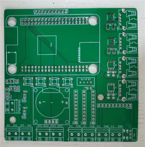
Back:

During soldering, first solder the surface-mount components, such as LEDs, resistors, CH340N capacitors, and capacitors. Then solder the headers, buttons, USB sockets, battery holders, and other connectors. Headers are used here for easy removal of the development board from the board. Finally, solder the development board's headers to the display screen and ADS1115 module, inserting them into the corresponding headers.
In addition, this project also designed a corresponding 3D hardware casing, using a top and bottom casing. The actual casing image is shown below:
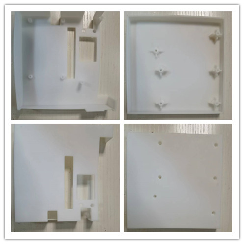
[Image of the actual casing] [
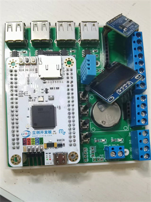
Image of the completed assembly can be inserted here]:
Bare machine without casing:
Finished product appearance after casing assembly:

Finally, this project inevitably has some problems; please leave comments for discussion. Thank you.


 京公网安备 11010802033920号

 CF1601-10RKI


