Project Overview:
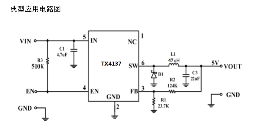
This project is a monolithic buck switch-mode converter using the TX4137 integrated power MOSFET. It achieves a peak output current of 0.6 A over a wide input power range of 5.5-60V, with excellent line voltage and load regulation. Utilizing PWM current-mode operation
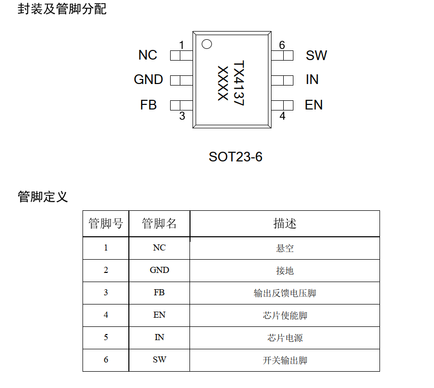
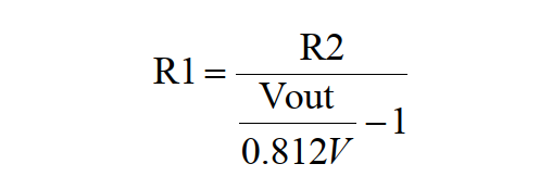
, the loop is easily stabilized and provides fast transient response. Integrated protection functions include cycle-by-cycle current limiting and thermal shutdown. It employs an SOT23-6 package and requires minimal external components . Features include : SOT23-6 package and minimal external components; 0.6A peak output current ; 0.9Ω internal power MOSFET ; large output capacitor startup capability ; low ESR ceramic capacitor for stable output ; up to 90% efficiency ; fixed 500kHz frequency ; thermal shutdown ; cycle-by-cycle overcurrent protection ; wide input voltage range: 5.5~60V ; SOT23-6 package applications : electricity meters ; distributed power systems ; battery chargers ; and pre-regulator principle analysis (hardware description). The EN pin (enable pin) is used to enable the chip. It can be controlled by an external MCU. For applications where the enable pin is not used, it is pulled up to the IN pin by a resistor of approximately 510KΩ by default and cannot be left floating. The output voltage is set by the voltage divider resistors R1 and R2 connected to the FB pin. The feedback resistor (R2) also sets the bandwidth of the feedback loop through an internal compensation network. The values for R1 are as follows: Input Capacitor Values: The input capacitor is used to reduce the inrush current of the input power supply and suppress switching noise. At the switching frequency, the capacitive reactance of the input capacitor must be less than the impedance of the input source to prevent high-frequency switching current from flowing into the input terminal. Low ESR and low temperature coefficient ceramic capacitors X5R or X7R can be used; a value of 4.7μF is sufficient for most applications. For applications with higher input voltages, an electrolytic capacitor should be connected in parallel at the input terminal to suppress input voltage spikes during power-on and power-off. Output Capacitor Values: The output capacitor maintains a small output ripple voltage and ensures the stability of the feedback loop. At the switching frequency, the capacitive reactance of the output capacitor must be sufficiently small. Low ESR ceramic capacitors X5R or X7R can be used; a value of 22μF is sufficient for most applications. Important Notes: PCB layout is critical to the stable operation of the circuit. Please follow these layout guidelines: 1) Keep the switching current path traces as short as possible and minimize the power loop area (the power loop consists of the input capacitor, MOSFET, and Schottky diode). 2) The connection path from power ground to Schottky diode to SW pin should be as short and wide as possible. 3) Ensure the feedback resistor is close to the chip and the trace is short. 4 ) The SW trace should be kept away from the FB feedback signal. 5) IN, SW, and GND should be connected with large copper foil to improve chip heat dissipation and enhance long-term stability.


 京公网安备 11010802033920号

 1107X40M00000BF


