Project Overview:
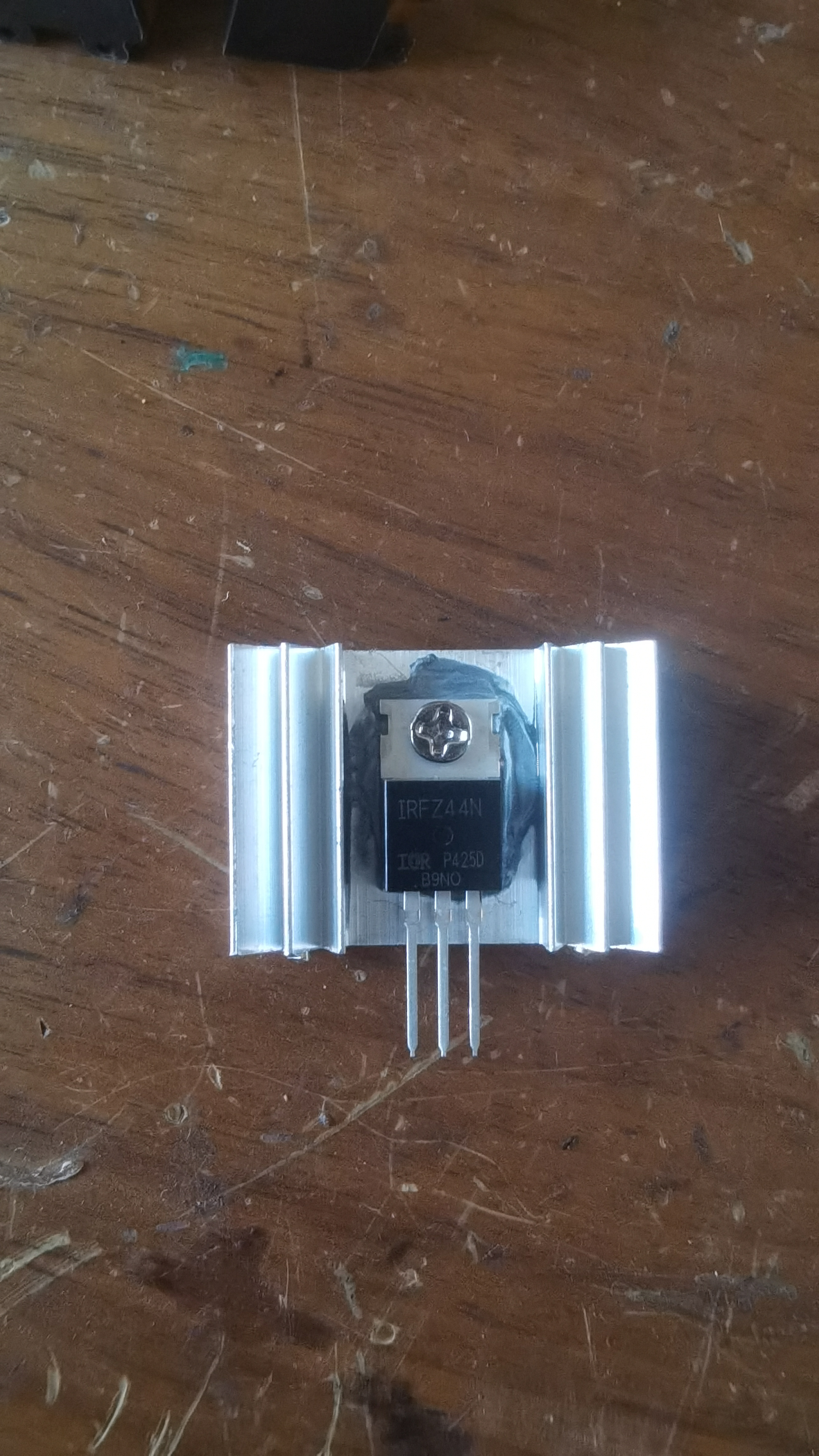
This project is an AC220V dual-button switch module based on the N-MOSFET IRFZ44N. It allows control of household appliances with a power rating of 7000W or less via a tactile switch.
Project Functions:
This design uses an AC220V dual-button switch module based on the N-MOSFET IRFZ44N. It features two independent buttons for on/off control, enabling low-voltage control of high-voltage (cold ground control of hot ground).
Power Supply
: A high-quality HiLink AC220V to DC12V 2W isolated switching power supply.
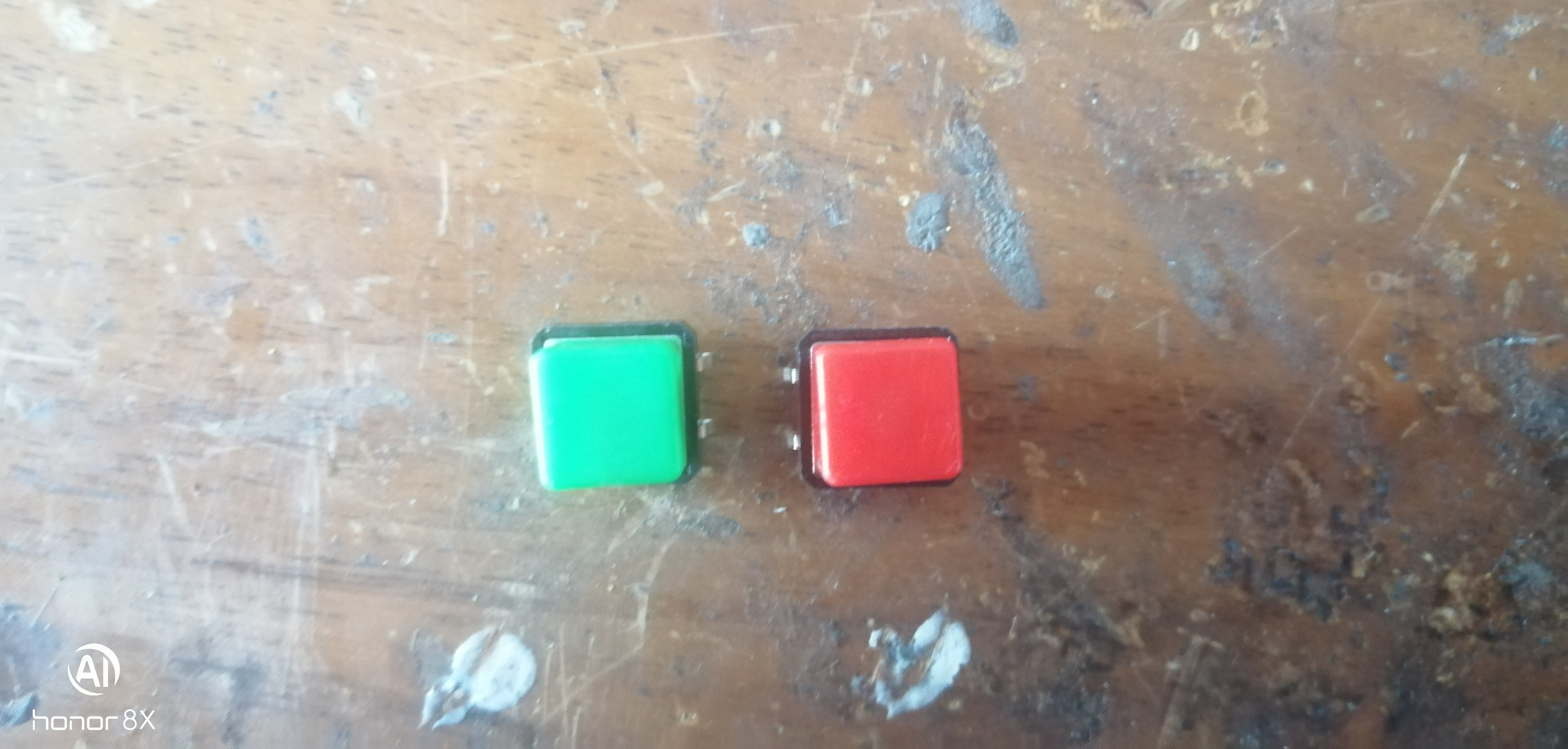
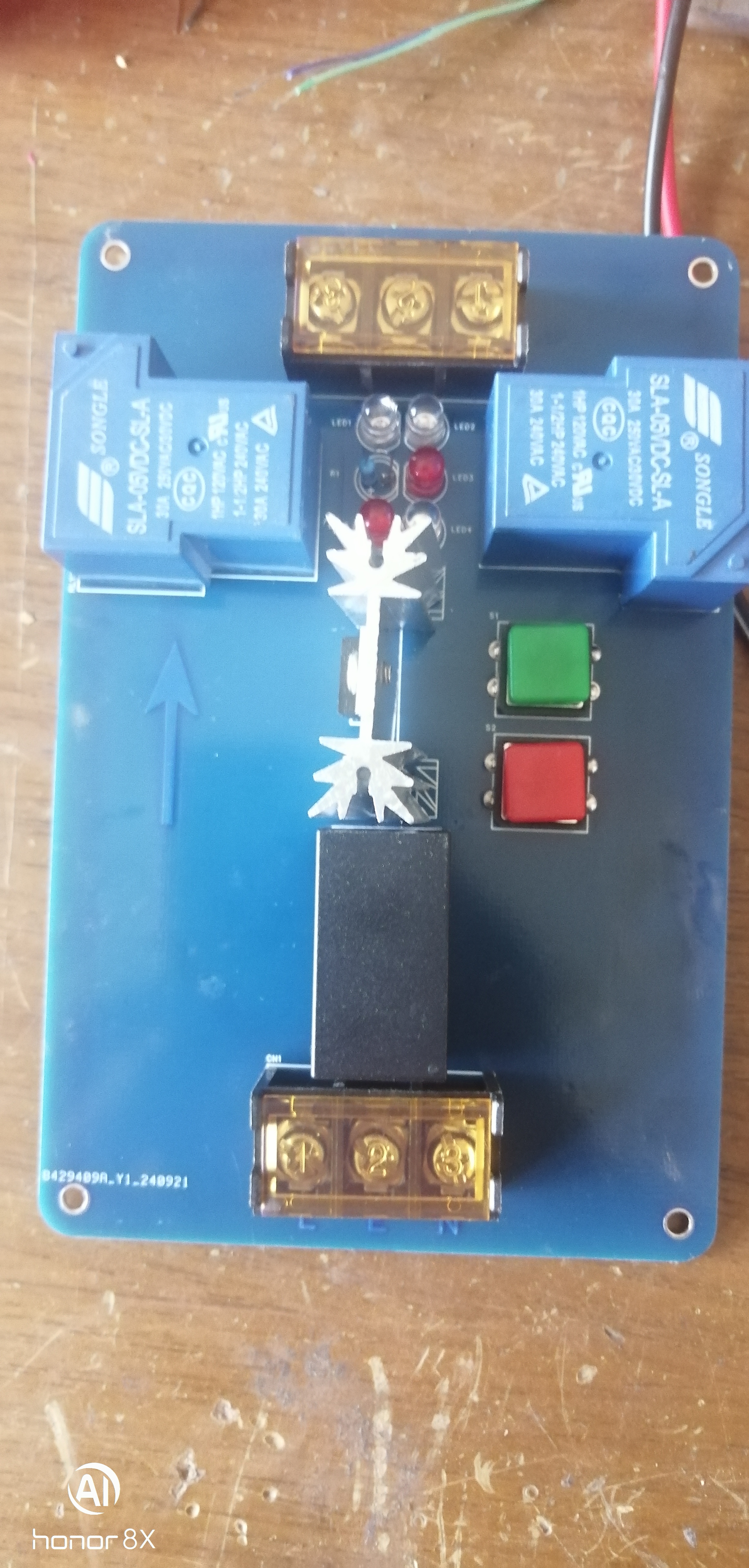
MOSFET on/off control is achieved using two 12×12×7.3mm tactile switches.
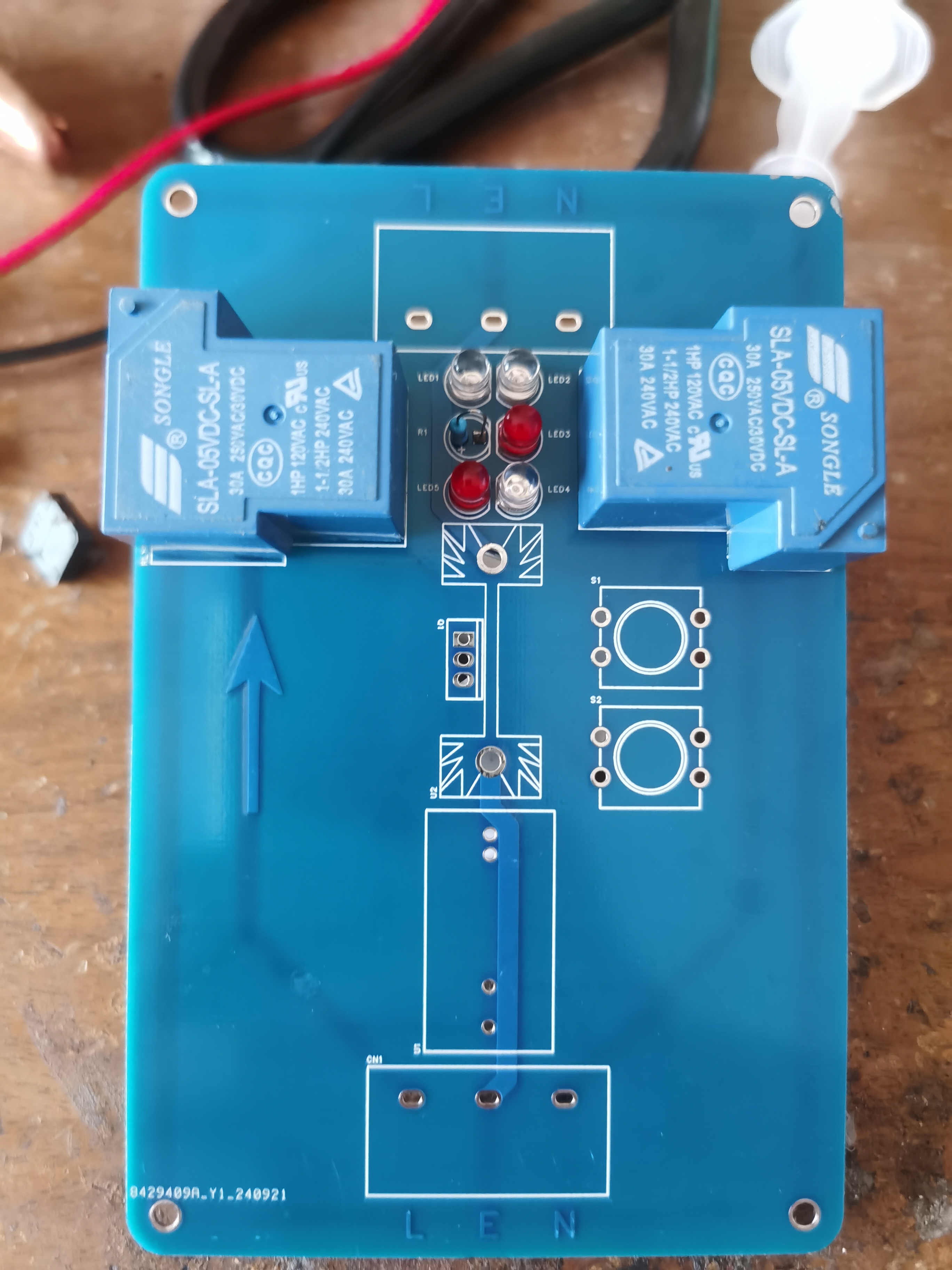
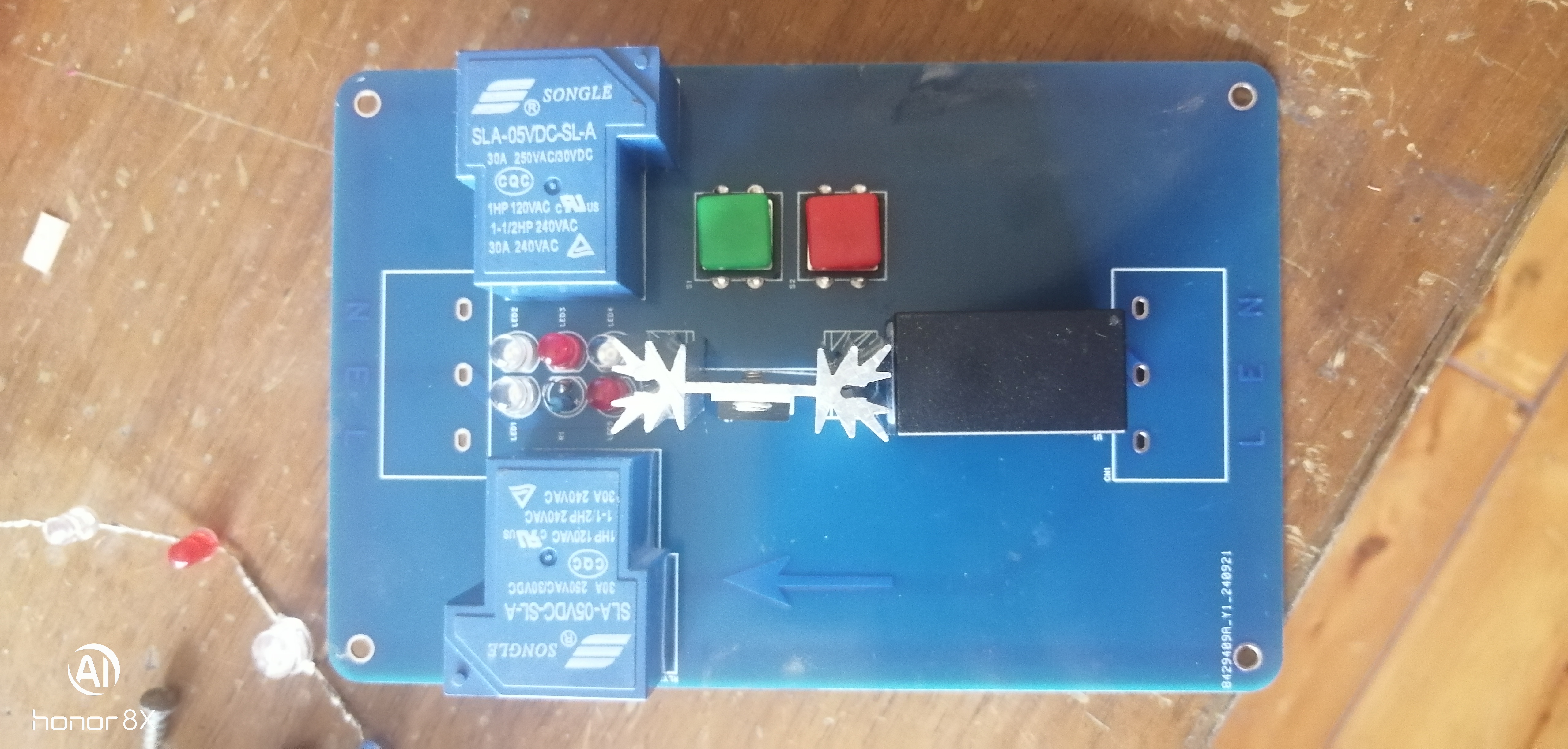
MOSFET outputs are connected to two 5V Songle high-power relays (each with AC250V 30A contact capacity and control coils connected in series). This dual-relay structure allows simultaneous closing and opening of the live and neutral wires, effectively preventing some appliances from continuing to operate after a power outage (such as LED bulbs).
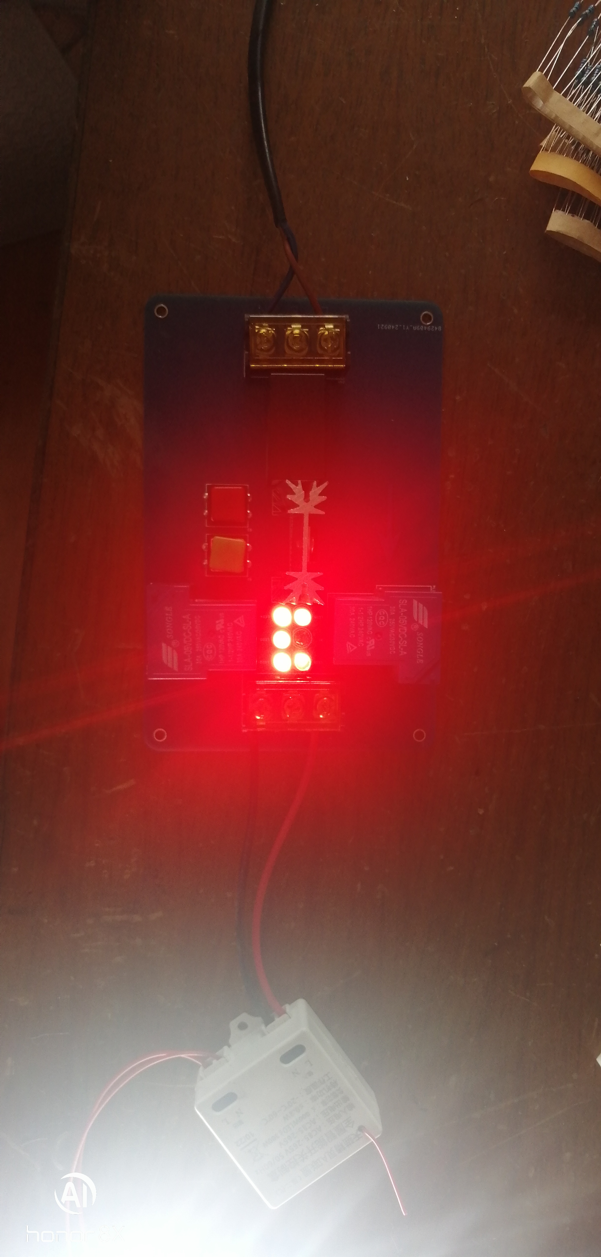
The MOSFET outputs also include five red LED power indicators, providing clear visibility of the appliance's operating status.
Principle Analysis (Hardware Description)
This project consists of a power supply section, a MOSFET control section, and a high/low voltage (hot/cold ground) isolation control section.
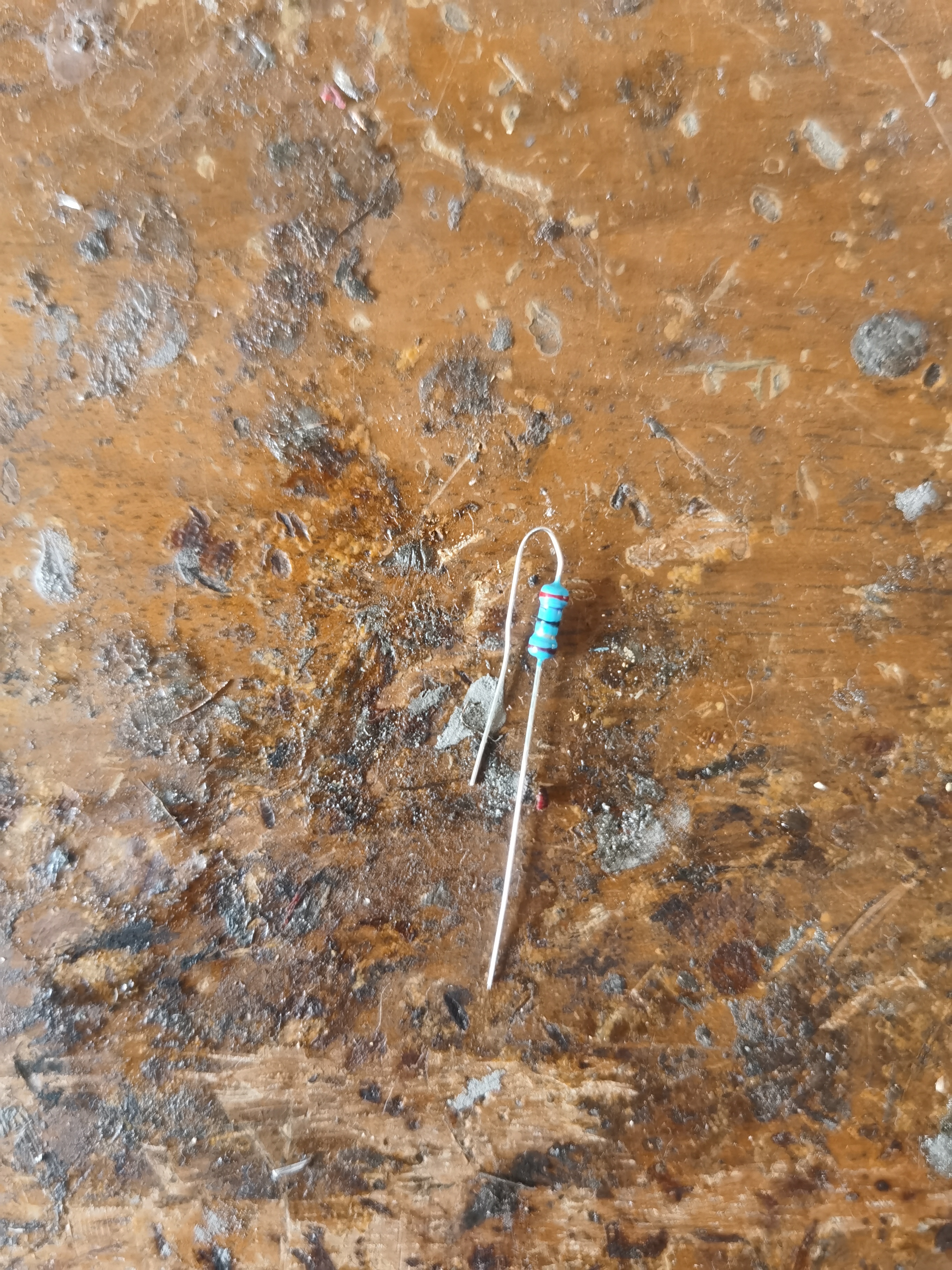
When the tactile switch S1 is pressed, the MOSFET conducts, the relay is energized, and the LED lights up; when the tactile switch S2 is pressed, the MOSFET is cut off, the relay is deactivated, and the LED turns off. R1 is the shunt resistor for the LED, with a resistance of 27Ω.
Precautions
: Assembling this project requires soldering skills;
when soldering the LED, pay attention to distinguishing the positive and negative terminals. Reversing the terminals will at least cause the circuit to malfunction, and at worst, reverse the circuit and damage the LED;
the circuit board needs to be grounded after assembly;
do not touch hot ground (high voltage) areas during use.
Assembly Process
: 1. Prepare materials
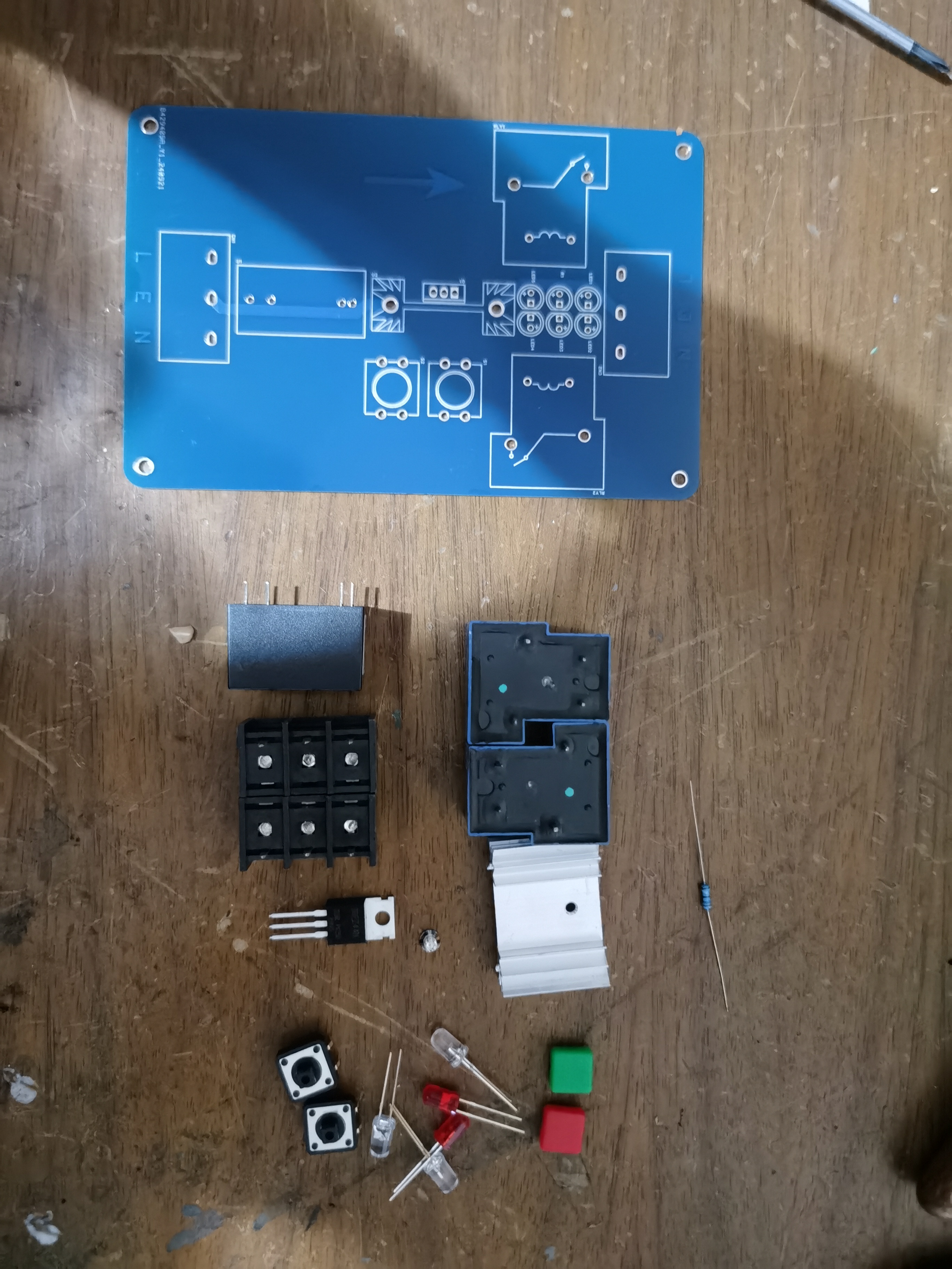
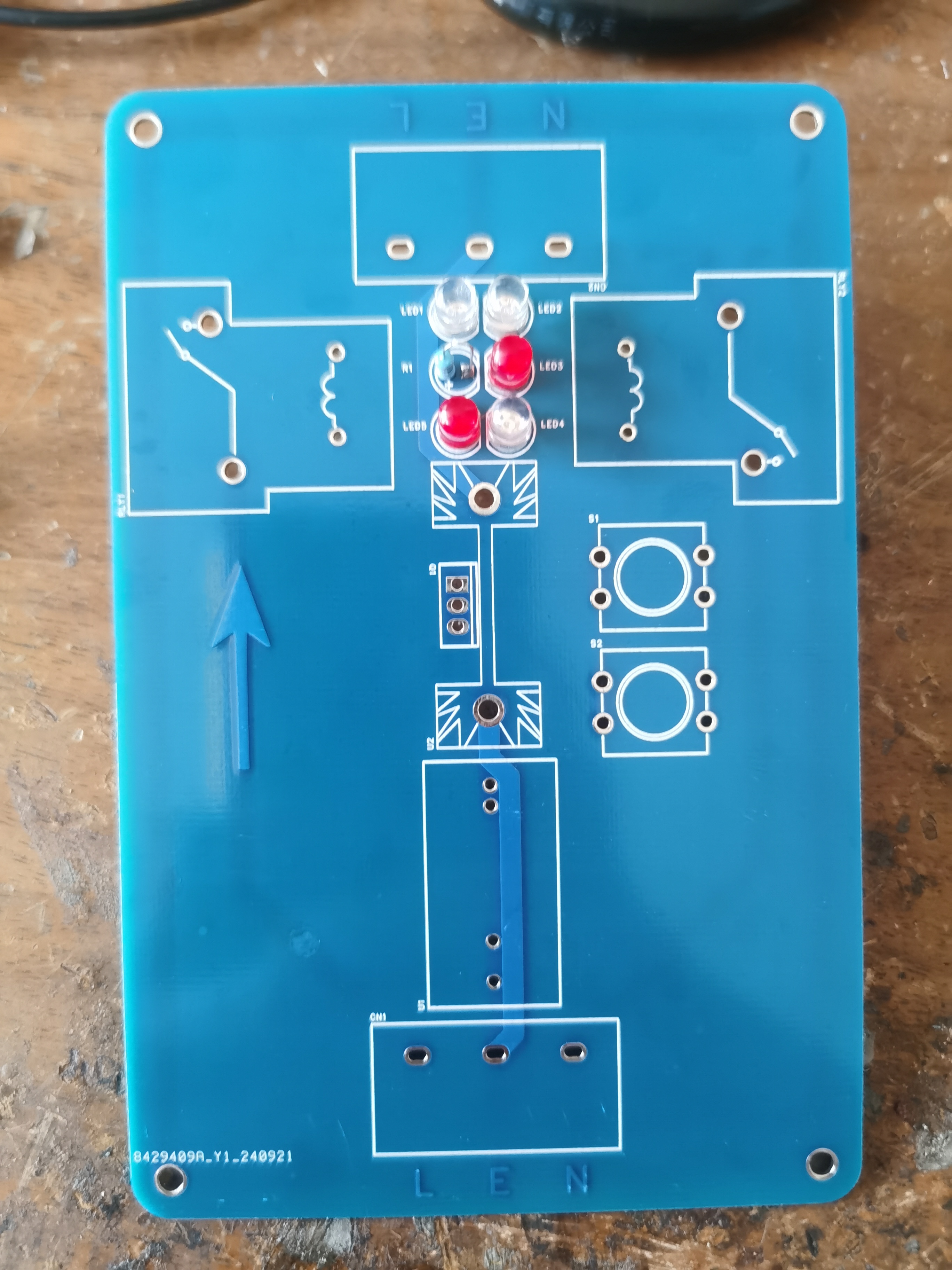
2. Install LEDs (Do not reverse them, remember!!!)
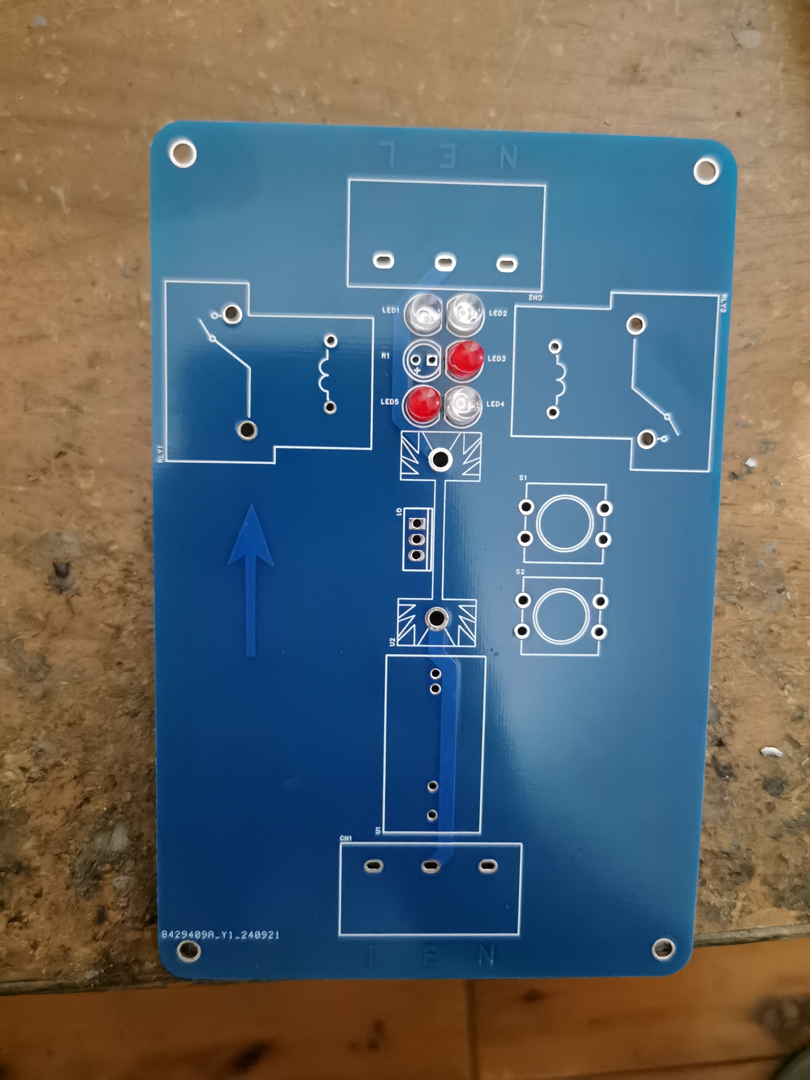
3. Install shunt resistors (no need to distinguish positive and negative terminals)
4. Install
relays 5. Install MOSFETs

6. Install tactile switches

7. Install switching power supply
8. Install terminal blocks
9. Clean the circuit board

Actual picture (final effect)
PDF_AC220V Double-Button Switch.zip
Altium_AC220V Dual-Button Switch.zip
PADS_AC220V Dual-Button Switch.zip
BOM_AC220V Double-button switch.xlsx
91918
Single-cell lithium battery capacity test 1.4.1
Supports batteries from 0.8V to 5V, with voltage accuracy within 0.001V and discharge current precisely controlled within 1mA. Unaffected by ambient temperature, it boasts high precision. This product has been calibrated using a 6.5-digit multimeter.
Supports batteries from 0.8V to 5V, with voltage accuracy within 0.001V error and discharge current precisely controlled within 1mA, unaffected by ambient temperature, demonstrating high precision. This product has been calibrated with a 6.5-digit multimeter.

Below are experimental records:
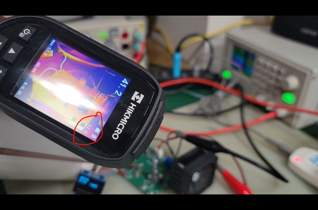
Discharge current 1A, consistently maintained around 1A when heated with a hairdryer to approximately 50 degrees Celsius.
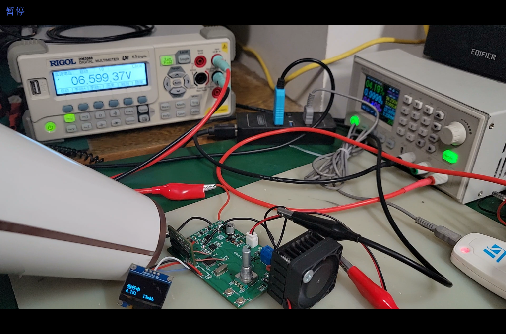
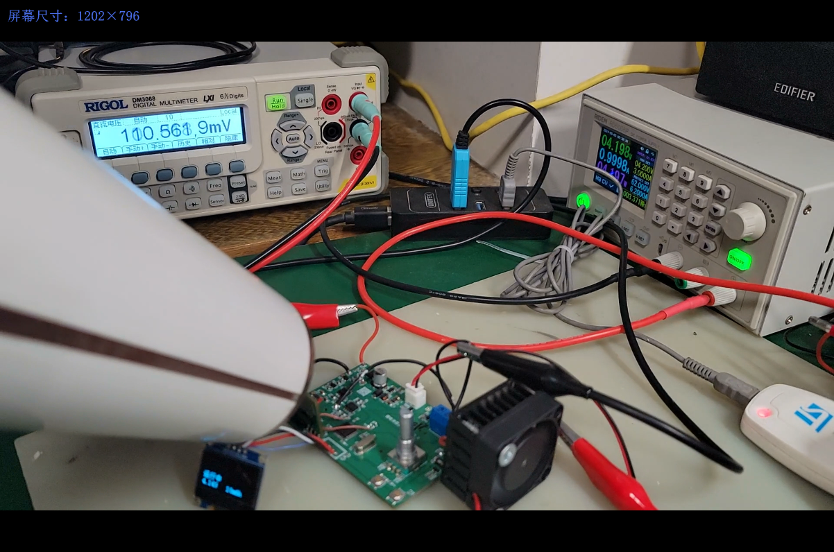
Next, regarding voltage accuracy, an adjustable power supply was used for visual comparison with a 6.5-digit high-precision multimeter to ensure the accuracy of the voltage and current readings. The


adjustable power supply was set to voltage 4.15V

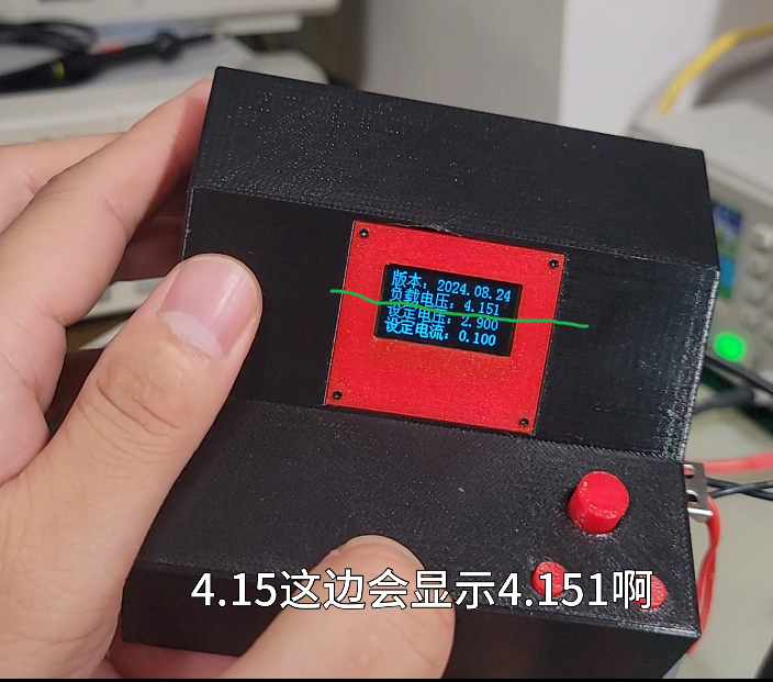
to begin current testing, with a constant discharge current of 0.1A.

For more detailed information, please see my Bilibili video: https://www.bilibili.com/video/BV1xSxieiEXN/?vd_source=527cf06b5801c7d3f8fe41d15300c1d4
PDF_Single-cell lithium battery capacity test 1.4.1.zip
Altium Single-Cell Lithium Battery Capacity Test 1.4.1.zip
PADS_Single-cell Lithium Battery Capacity Test 1.4.1.zip
BOM_Single-cell lithium battery capacity test 1.4.1.xlsx
91919
USB-HUB
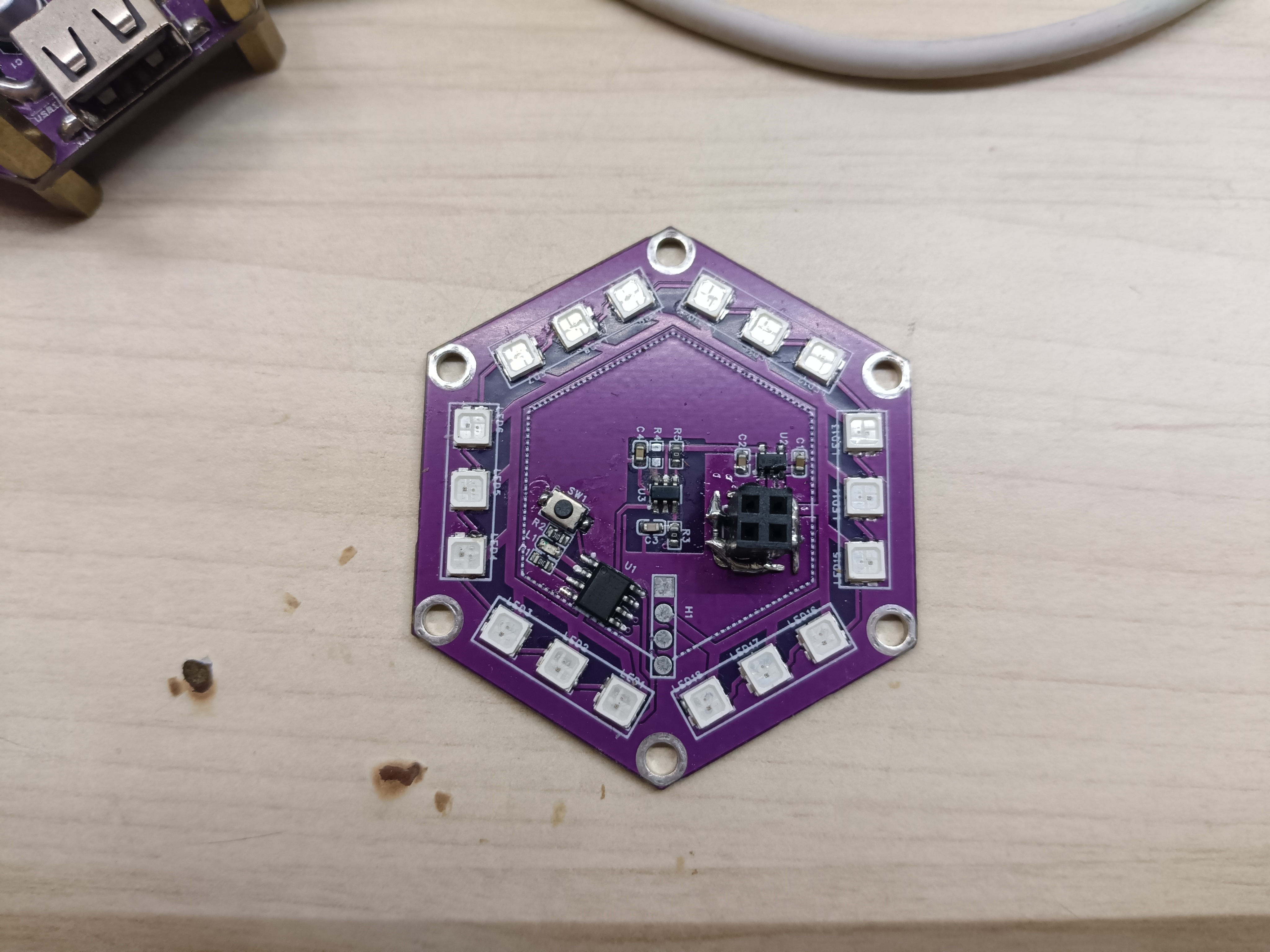
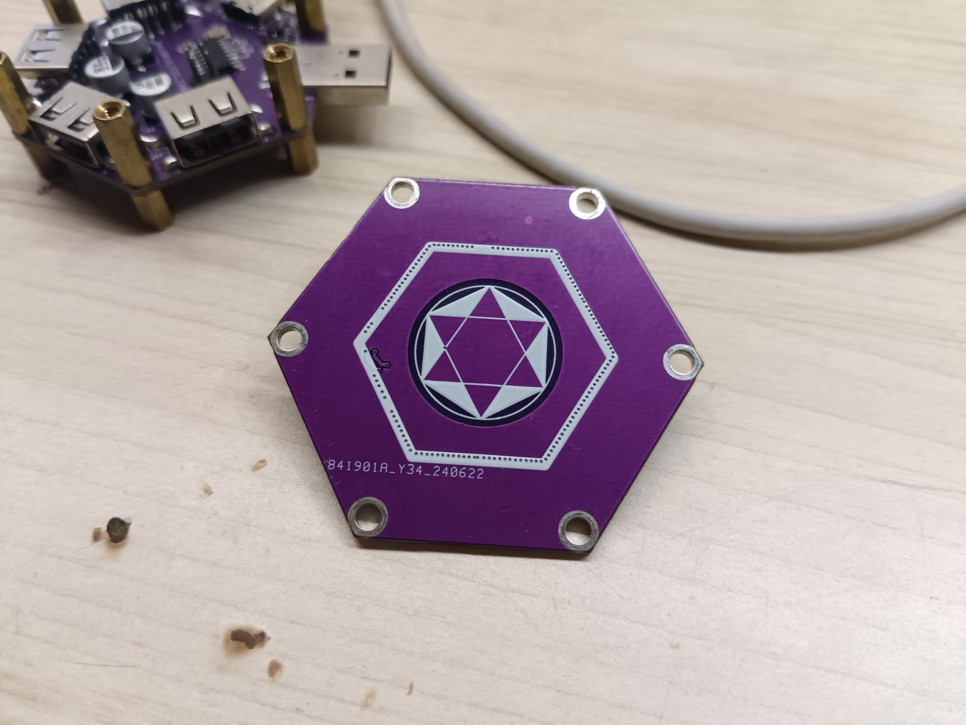
A 4-port USB hub based on SL2.1A, with top and bottom covers.
This is a USB 2.0 hub, not supporting USB 3.0. Since it's based on the SL2.1A board, its primary function is serial port expansion, which is sufficient. There's also a cover for lighting effects, based on an STC8G1K08A LED with WS2812 LEDs. Because the SL2.1A lacks port status output, it doesn't support microcontroller detection of which port is connected. The plan is to implement this effect using an FE2.1 board and a microcontroller in the future. See the attached image
for


sample microcontroller code and BOM.
RGB.zip
BOM_Vacation_Use_Schematic6_2024-09-29.xlsx
BOM_Vacation_Use_Shell_Schematic7_2024-09-29.xlsx
PDF_USB-HUB.zip
Altium_USB-HUB.zip
PADS_USB-HUB.zip
BOM_USB-HUB.xlsx
91920
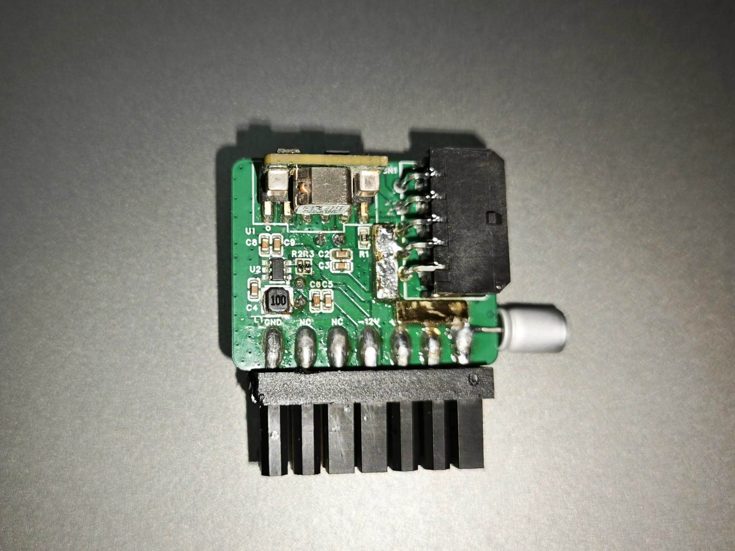
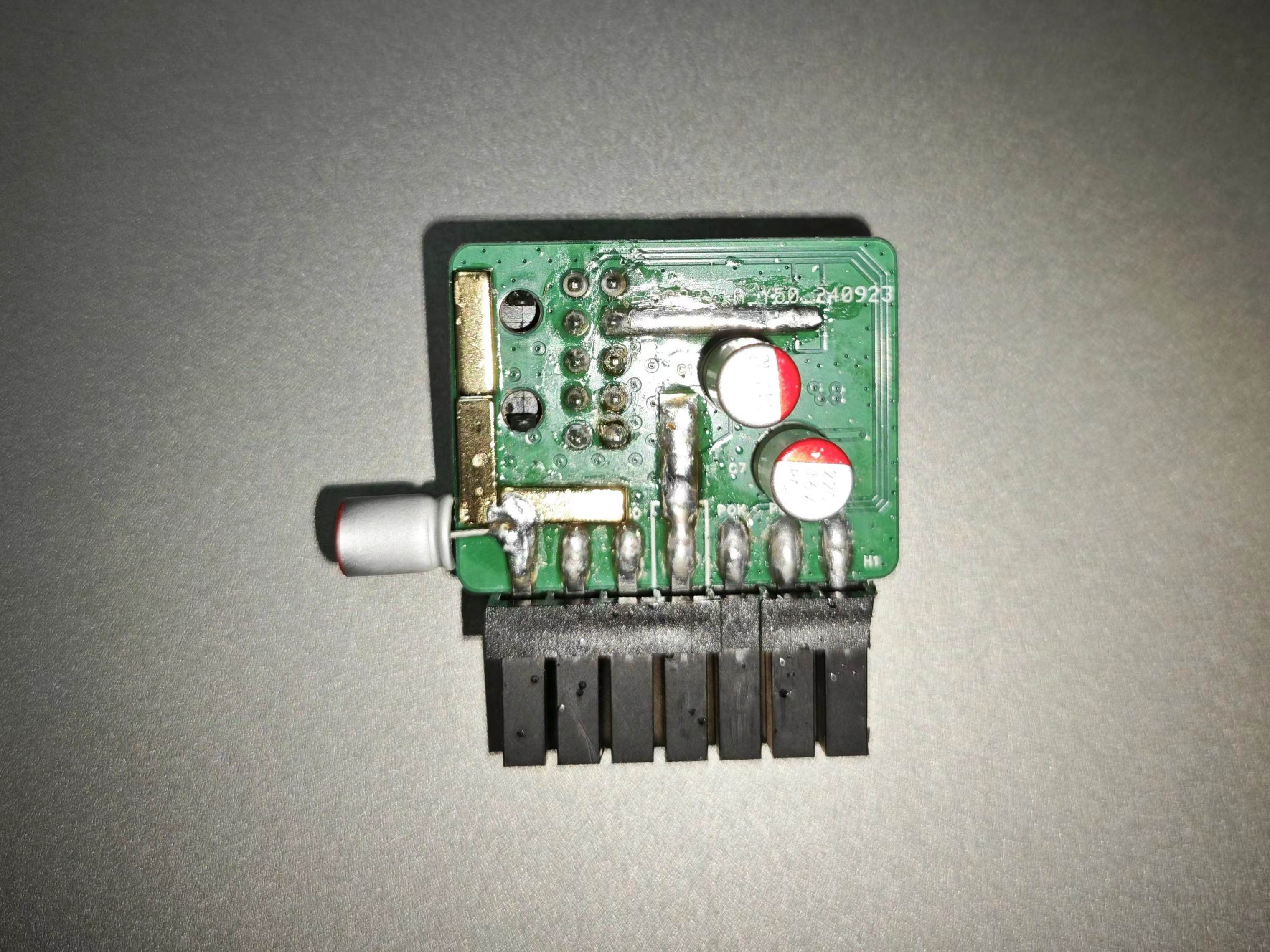
CSPS/ATX12VO to Lenovo motherboard 14-pin adapter board
Connect the output of the CSPS power adapter board to the 14-pin connector on the Lenovo desktop motherboard.
CSPS/ATX12VO to Lenovo Motherboard 14Pin Adapter
Change Log
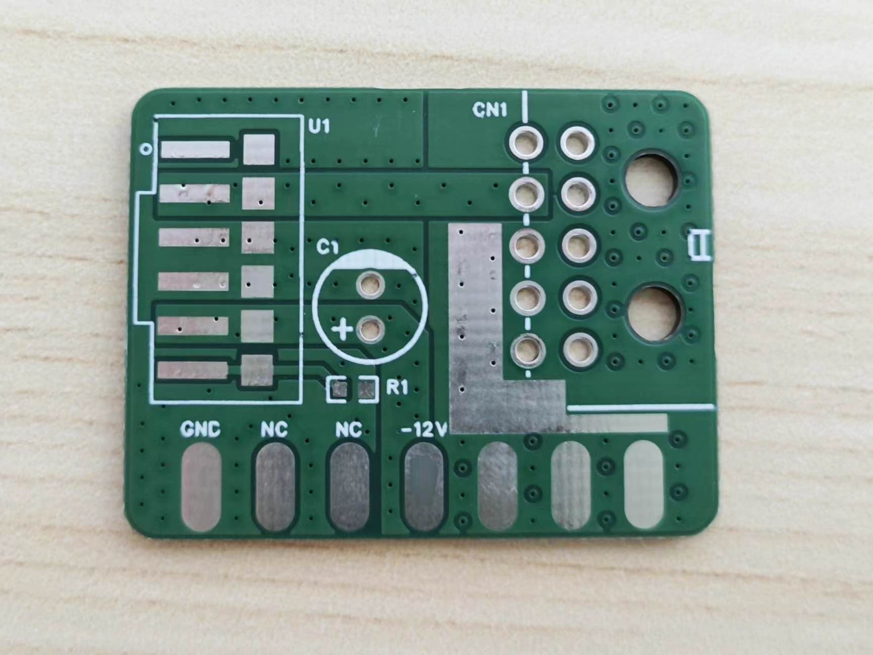
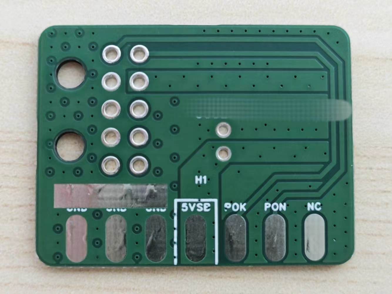
v2.0 2024-09-29: Added -12V power supply for serial port module use; adjusted solder mask opening shape for easier copper strip soldering.
v1.1 2024-07-13: Added 12V and GND solder mask openings to the PCB, added more seam holes and optimized via layout, and fine-tuned component positions. Schematic unchanged.
v1.0 2024-06-07: Initial Design
Background
Using a high-volume, fully-equipped CSPS server power supply on a standard ATX motherboard requires multiple power rails (12V, 5V, 5VSB, 3.3V, etc.). However, branded motherboards like those from Lenovo have already adopted 12VO, with Lenovo's 14-pin motherboard requiring only 12V and 5VSB rails at most. The remaining 5V and 3.3V voltages are automatically stepped down by the motherboard, greatly simplifying the adapter board design.
The design and implementation
are modified from Harry's ATX12VO adapter board, using a ZXDN10 to step down the 12VSB to 5VSB output. Soldering the ZXDN10 is convenient using a hot plate. Since there's no longer a need to convert 5V and 3.3V, the ATX voltage monitoring and protection chip can be omitted, and the CSPS's PS_OK and PS_ON signals can be directly connected to the motherboard. Although theoretically, the PS_OK delay of CSPS is not within the ATX standard range, it doesn't cause any problems in actual use.
The adapter board input uses the ATX12VO standard wiring sequence and an MX3.0 10-pin connector, mainly for compatibility with existing adapter boards and cables. If only considering the CSPS power supply and not the ATX12VO standard, then replacing it with an MR30 + 2-pin ribbon cable might be a more cost-effective and simpler option. The output uses a clip/soldering board type 5557 connector. Currently, only one seller on Taobao (Huixishi Zex Connector) is available, but they don't have a 14-pin model. You need to buy an 18-pin connector and cut off the 4 pins yourself, paying attention to the direction when cutting.
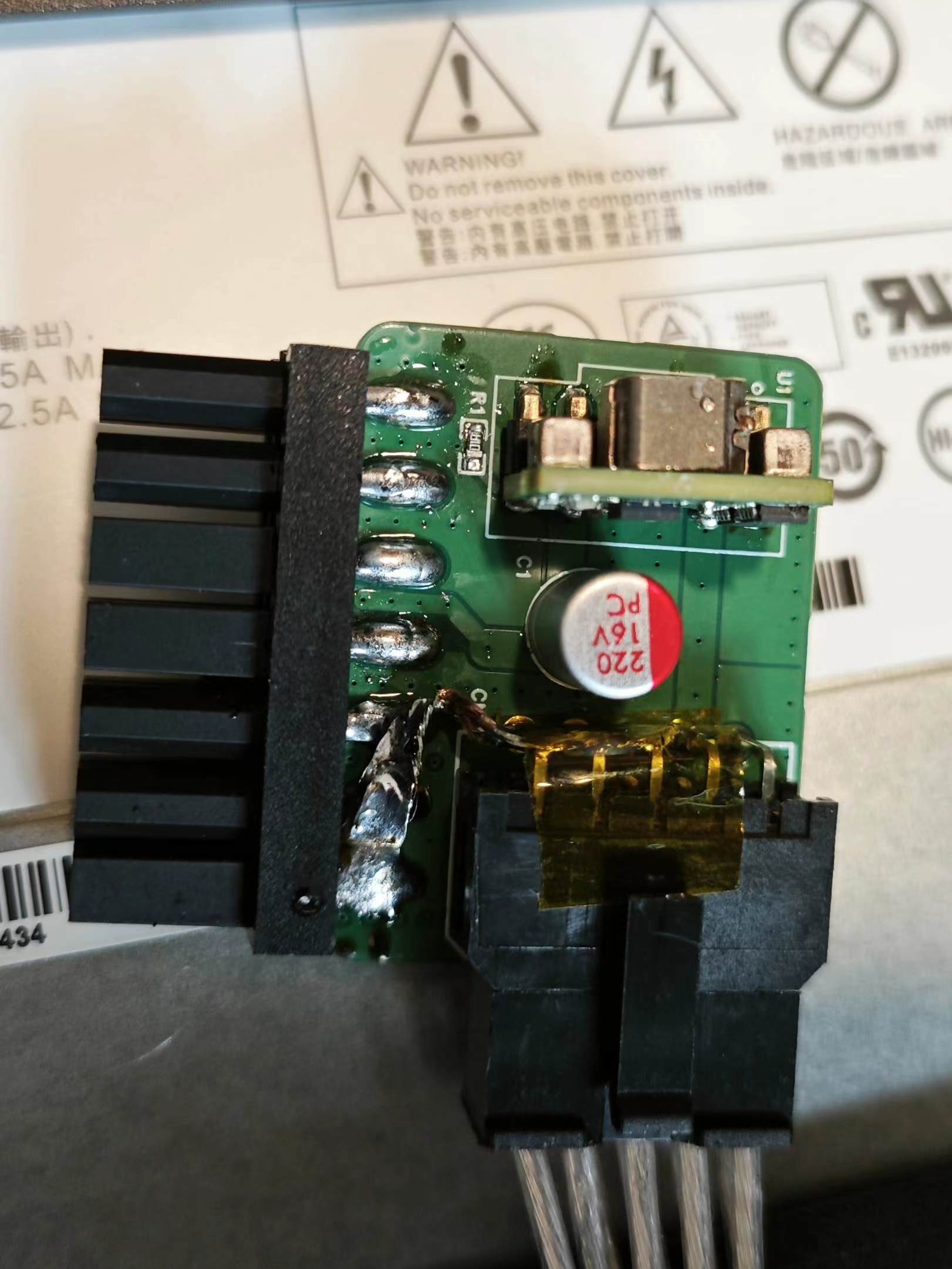
The serial port module on the motherboard requires -12V power, but the ATX specification doesn't have specific requirements for the -12V current and timing (referring to other ATX power supplies, the -12V output capability is usually a few tenths of an amp), and the bias voltage requirements are also relatively lenient. Therefore, a simple Buck circuit is used in the adapter board to step down the 12V to -12V. If the serial port is not needed, related components can be omitted.
The 12V, GND, 12Vsb, and 5Vsb lines have solder mask openings; soldering or adding copper strips can improve current carrying capacity.
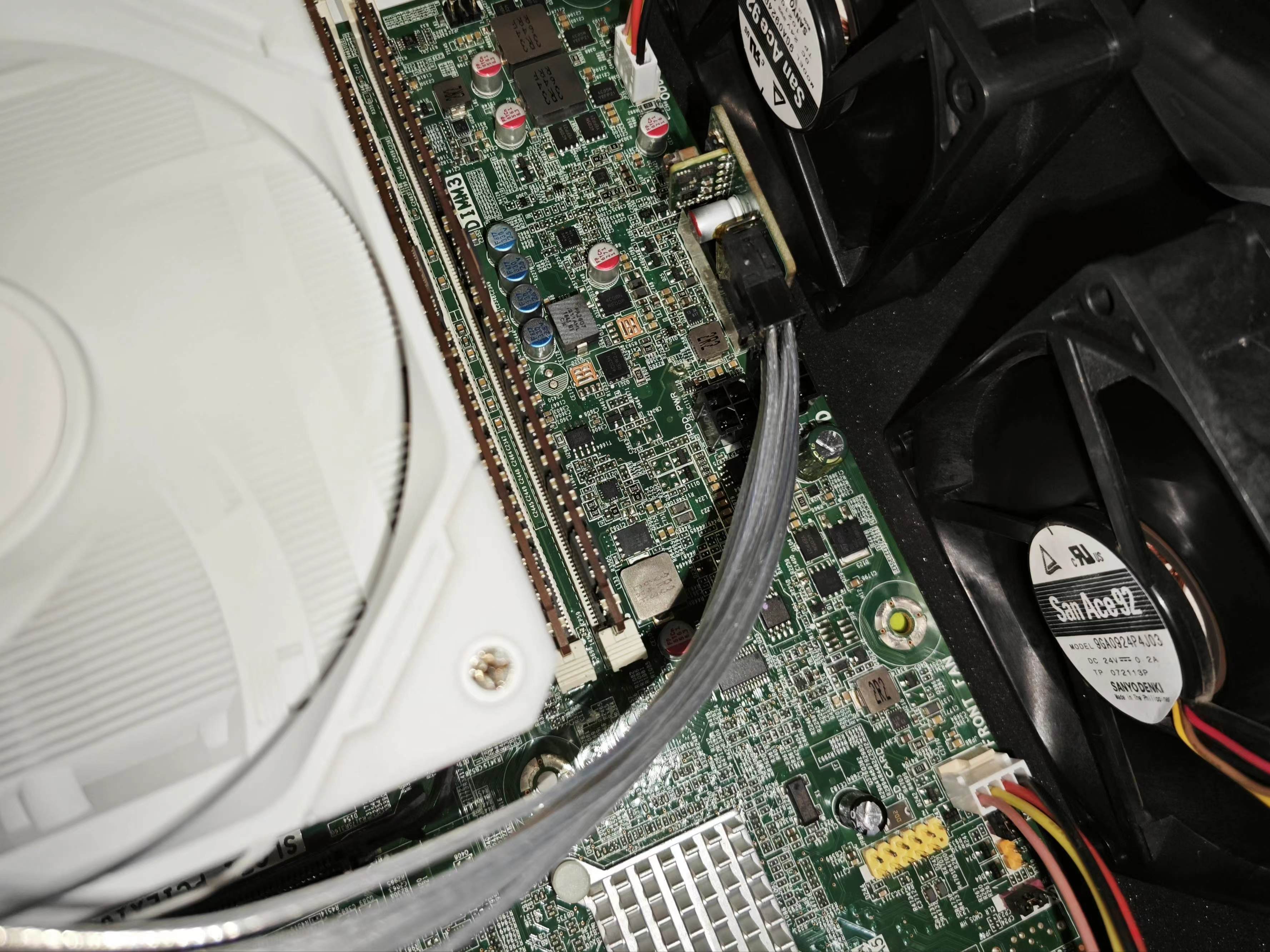
Testing was conducted
using a PS-2751-7H power supply, and it worked normally on a P410 workstation motherboard.
Known issues:
v2.0
Buck input capacitor capacitance is too low, which may cause increased 12V ripple. This can be alleviated by manually adding a capacitor (see actual image);
the 5Vsb front solder mask is not exposed;
the voltage rating of the Buck capacitor selection can be appropriately reduced (e.g., 25V MLCC, 16V for solid-state through-hole);
the Buck layout can also be optimized for a more compact design.
Images
of v2.0 and
v1.1
are only prototype PCBs and have not been tested on a machine.
v1.0

References :
ATX Power Supply Plan - Harry_2005
, KCORES-CSPS-to-ATX-Converter
PS-2751-7H,
ATX Power Supply Specification - Intel
ZXDN10, Information: A review of recently acquired used DC non-isolated buck modules - Muyu
PDF_CSPS-ATX12VO to Lenovo Motherboard 14Pin Adapter Board.zip
Altium_CSPS_ATX12VO to Lenovo Motherboard 14Pin Adapter Board.zip
PADS_CSPS_ATX12VO to Lenovo Motherboard 14Pin Adapter Board.zip
BOM_CSPS_ATX12VO to Lenovo Motherboard 14Pin Adapter Board.xlsx
91921
L9110 Four-Way Motor Module
Imitating the L9110S four-channel motor drive module found on Taobao
Project Description:
The L9110S four-way motor drive module found on Taobao requires resistors and capacitors.
This project uses a different manufacturer's chip with a simplified external circuit, achieving a module with the same function and verifying the feasibility of the simplified circuit.
Project Function:
Drives four motors. The module size is designed for four-wheel drive in a robot.
Project Parameters
: This design uses HGSEMI (Huaguan) motor drive chips. Other manufacturers' chips may require external resistors and capacitors.
This circuit can be used with other L9110S motor drive chips that do not require external circuitry.
PDF_L9110 Four-Way Motor Module.zip
Altium_L9110 Quad Motor Module.zip
PADS_L9110 Quad Motor Module.zip
BOM_L9110 Four-Way Motor Module.xlsx
91923
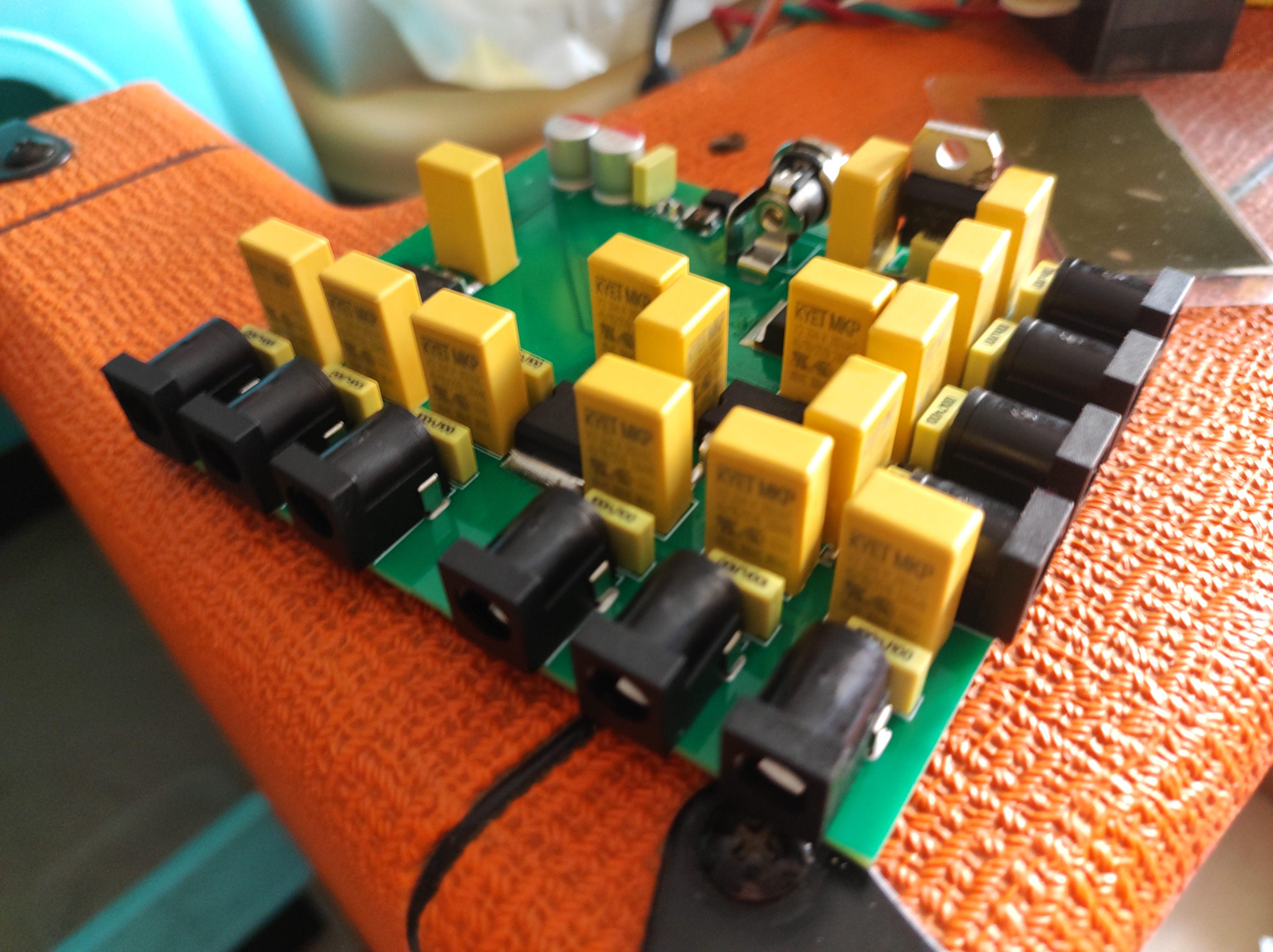
10-channel effects power supply with isolation* Please do not order, as the casing documentation is problematic.
Use ferrite beads for isolation. The power supply must be a medical-grade/printer power supply with negative ground. Adjust the wiring according to the interface. The latest version uses a 24V Mean Well medical-grade power supply GSM40A A24 (V-connects to AC FG).
Solder the capacitors in reverse, or modify the casing. The current one won't fit!
The left side of the PCB can be spot-soldered to the outer casing,
but sparks are observed during insertion. The new design eliminates redundant capacitors;
the outer casing has not been verified.
Mioka Meow Effects Power Supply .stp
Mioka Cat Effects Power Supply V2 (order this one).stp
Mioka Nyan's Electric Guitar Effects Pedal V2 (Correction) (This is the correct one to order).stp
Mioka Cat Effects Power Supply V2 (Second Correction) (This should be the one you ordered and won't change again. .stp)
Spark-optimized (latest) (unverified) .stp
PDF_10-channel effects power supply with isolation_Please do not order, the casing file has a problem.zip
Altium_10-channel effects power supply with isolation_Please do not order, the casing file has a problem.zip
PADS_10-channel effects processor with isolated power supply_Please do not order, the casing file has a problem.zip
BOM_10-channel effects power supply with isolation_Please do not order, the casing file has a problem.xlsx
91924
STM32 Development Board - Expansion Board
STM32 Development Board - Expansion Board
Background of Developing an Automotive Communication Learning Expansion Board Based on the Skystar Expansion Board
: Due to the urgent need for learning automotive electronics-related knowledge, a main control board for testing automotive components needs to be developed to meet the testing and learning requirements of automotive electronic products.
Objective: To develop an automotive communication learning expansion board based on the Skystar expansion board, integrating multiple functions such as dual-channel CAN communication, UART serial communication, ADC analog signal reading, button control, and wireless network communication .
Schematic Diagram Explanation:
1. Dual-channel CAN Communication: Integrates two channels, communication CAN and diagnostic CAN, using two domestic SIT1042 chips to read data and fault information of automotive components.

2. UART Serial Communication: The UART serial communication interface directly uses the core board interface for data transmission with the host computer.
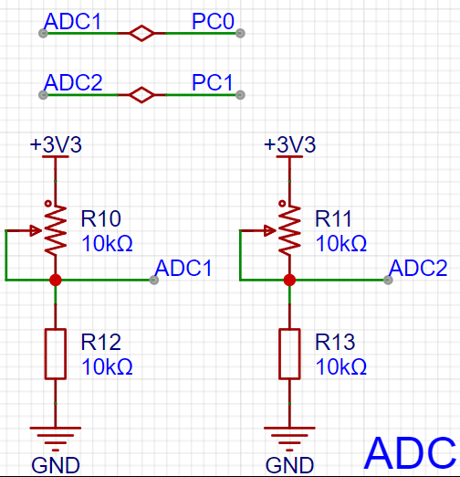
3. ADC Analog Signal Reading: Uses two 10k adjustable resistors to simulate data from two sensors, facilitating circuit debugging and testing.
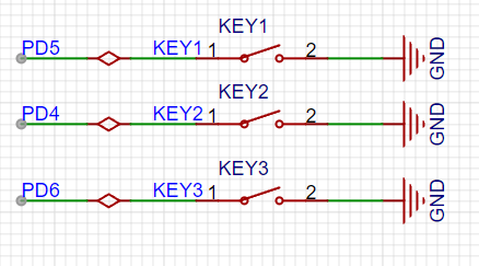
4. Button Control: Equipped with three buttons, allowing control of the test status or the host computer software, achieving human-machine interaction and improving operational efficiency.
5. Wireless Network Communication: Integrated wireless network functionality supports data transmission to the host computer, enabling remote monitoring and control. It uses an ESP8266 module connected to the core board via a serial port.

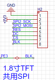
6. Display Screen and LED Indicators: Equipped with a 1.8-inch TFT display screen for setting test parameters and displaying test results. Integrated LED indicators show the test and communication status for quick and easy understanding of the operating status.
Verification Results:
Functionality and circuitry are working normally!

PDF_STM32 Development Board-Expansion Board.zip
Altium_STM32 Development Board - Expansion Board.zip
PADS_STM32 Development Board - Expansion Board.zip
BOM_STM32 Development Board-Expansion Board.xlsx
91926
01-EYE_V1.0
The prototype for Project 01-EYE is the Espressif ESP32-S3-EYE_V2.2 development board. This small AI development board features a 2-megapixel camera, a 1.69-inch capacitive touchscreen, and a digital microphone, suitable for applications such as image recognition and audio processing.
![01-EYE project.png]

PDF_01-EYE_V1.0.zip
Altium_01-EYE_V1.0.zip
PADS_01-EYE_V1.0.zip
BOM_01-EYE_V1.0.xlsx
91928
electronic


 京公网安备 11010802033920号

 2200CAG1009B2MB


