Blood pressure (BP) measurement based on PTT non-invasive non-pneumatic blood pressure
monitor is an important part of diagnosing diseases, observing changes in the condition and judging the treatment effect. At present, blood pressure measurement methods are mainly divided into invasive detection and non-invasive detection [1]. Invasive detection measures the blood pressure value at a certain moment through strain gauge. However, this method is prone to causing bacterial infection in patients, cannot be measured continuously, and has many limitations. It has gradually faded from public view. Non-invasive blood pressure detection methods are divided into Korotkoff sound method, oscillometric method, volumetric vibration method and pulse wave measurement method. At present, the traditional cuff non-invasive blood pressure device is commonly used to measure blood pressure. This type of device uses the Korotkoff sound method to listen to the vibration of blood and obtain systolic and diastolic pressure within a fixed or long time interval (usually more than 15 minutes). Although the measurement effect is very good, there are many drawbacks.
First, it cannot be measured continuously. Generally, it is necessary to measure the blood pressure value 1 to 2 times and take the average value as the true blood pressure value of the subject. Second, the width of the cuff and the tightness of the cuff to the measurement site will have a certain impact on the measurement results. Finally, when measuring blood pressure, the cuff and stethoscope should be kept close to the skin as much as possible so that the blood pressure measurement can be as accurate as possible. This means that when using non-invasive blood pressure devices with cuffs, we must first "take off our clothes or roll up our sleeves". Especially in winter, the correct way to measure blood pressure is to take off our clothes so that the upper limb on the side to be measured is fully exposed. However, a study published in the Chinese Journal of Hypertension [1] stated that taking off clothes will cause blood pressure to rise significantly, and the more clothes are removed, the more obvious the rise will be. Secondly, this type of blood pressure measurement takes a long time and cannot be measured continuously. Multiple measurements of the upper limb will cause the result error to gradually increase. At the same time, the measurement experience provided by long-term air pressure restraint is not comfortable. In addition, this method cannot be used for some special groups such as patients with skin injuries and patients with mental illnesses.
Therefore, it is of great significance to design a portable, comfortable, accurate and continuous blood pressure measurement scheme.
The pulse transit time (PTT) method is a research hotspot in the application of continuous non-invasive blood pressure. Its principle is to calculate the systolic and diastolic blood pressure of the subject by calculating the time difference between the ECG and PPG peaks of the subject and combining multiple physiological signals. This method differs from traditional blood pressure measurement by eliminating the need for pressure on the limbs, allowing for stable, convenient, continuous, and accurate blood pressure measurement.
Requirements analysis
necessitates portability, requiring battery power and wireless transmission; therefore, a 3.7V lithium battery was chosen. The operating current is below 20mA, while the main control chip requires 3.3V power and Bluetooth requires 5V power; therefore, LDO-type voltage regulators were selected, providing 3.7V to 3.3V and 3.7V to 5V conversions respectively. The AD8232 chip was chosen for ECG signal acquisition due to its stable output and low power consumption. The MAX30102 digital pulse wave sensor was selected for PPG signal measurement, acquiring pulse waves through frequency division dual-wavelength acquisition. An ADC is used to receive analog signals from the AD8232, and I2C communication is used to receive digital signals from the MAX30102. Wireless transmission is required, hence the choice of Bluetooth HC-05. The host computer needs to display ECG and PPG waveforms while performing digital filtering, peak recognition, and other computational processing; therefore, MATLAB AppDesigner was selected.
Overall Design Scheme Block

Diagram Schematic Design Description
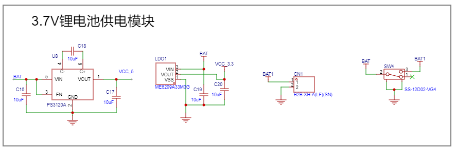
Power Supply Module
: Powered by a 3.7V lithium battery, with a direct-plug connection for easy battery replacement or charging. A sliding switch controls the main power supply. A 3.7V to 3.3V chip provides a 3.3V output to power the main control chip; a 3.7V to 5V chip provides a 5V output to power the Bluetooth module. Note the common ground handling in the circuit.
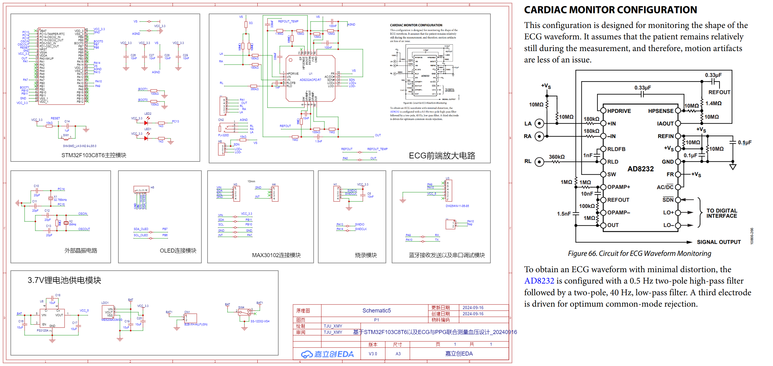
2. ECG Acquisition Module:
The AD8232 is used as the ECG front-end acquisition module. Design this part of the circuit according to the AD8232 datasheet (as shown in the right figure). Note that a pull-up resistor needs to be set to a high level on the SDN+ pin to start the chip. The headphone jack is used to connect to the ECG leads. Spare connection pins and circuit test pins are reserved. For detailed data such as the specific frequency response of the AD8232, please refer to the complete AD8232 datasheet.

3. The PPG acquisition module
has a reserved port for a through-hole MAX30102 connector. Connecting the MAX30102 to the PCB board via this port helps separate the MAX30102 from the main circuit board, improving the user experience.
4. OLED Display:
This screen is an optional feature and not the primary display solution for this program. Reserving this port facilitates future screen display functionality.
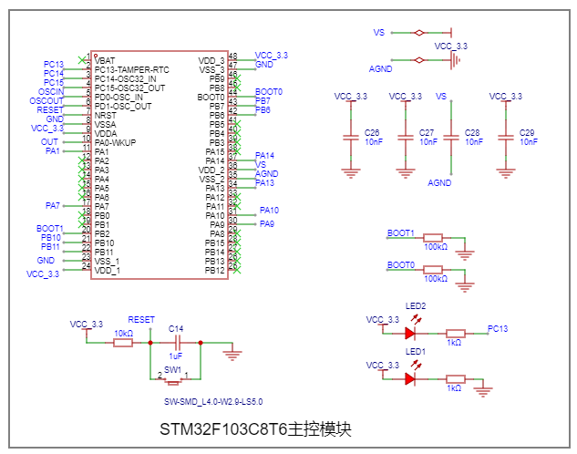
5. Main Control Chip:
The main control chip is an STM32F103C8T6. When powering on, ensure the decoupling capacitors are connected to the power supply and output ports of the four chips respectively; ensure a reset button is provided; this program only uses the dual-BOOT low-level programming method, therefore no jumper cap is provided. If additional programming and debugging methods are required, please reserve pins and jumper caps for the dual-BOOT; reserve programming pins and serial port pins for wired connection to facilitate program programming and debugging; ensure the required chip pins and corresponding connections are set correctly, and disable unnecessary pins.
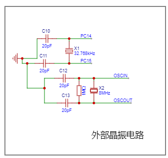
6. External Crystal Oscillator:
To achieve higher performance, a high-speed external crystal oscillator is used.
The complete schematic diagram is shown below.
PCB Design
Notes: This section includes some PCB design notes, such as PCB layout, routing, trace width, spacing, etc.
Power Supply Module
: Although this design is for low power consumption, the power supply module, as a main circuit, should ideally have thicker traces. Most power lines are 24 miles wide. Due to the limited spacing of chip pins, the power lines connected to the chips gradually transition from 10 miles to 24 miles.
Signal Lines
: All lines except power lines are signal lines, and all signal lines use a 10-mile trace width.
Vias
: All electrical connection vias have an outer diameter of 24 miles and an inner diameter of 12 miles. The positioning vias at the four corners of the PCB have an outer diameter of 4 mm and an inner diameter of 3 mm.
Crystal Oscillator Circuit :
Since the crystal oscillator section contains high-speed signals, its routing should be differential signal lines. Vias should be used around it, with the diameter of the surrounding isolation vias being 24 miles outer and 12 miles inner. The vias are connected to the ground plane, and the internal crystal oscillator area surrounding the vias is designated as a copper-free zone (this zone should not be limited to the top layer but should be multi-layered, i.e., all layers). No copper pouring is applied to this area to isolate high-speed signals from low-speed signals.

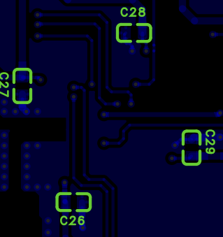
5. Decoupling Capacitors
: Decoupling capacitors should be connected according to the spatial structure of the schematic. For example, the decoupling capacitors for the four power pin pairs of the STM32F103C8T6 need to be installed near each power pin pair, as shown in the figure.
6. Copper Pouring
: GND vias should be used effectively to achieve full copper pouring, especially in areas with complex signal lines. Copper pouring near signal lines can reduce external interference and improve signal stability.
7. Cross Connections and Teardrop
Routing: Orthogonal routing should be used whenever possible. Sharp angles should be avoided. Teardrop routing should be used for cross connections. Teardrop routing should be applied to all components requiring electrical connections, including chip pins and vias.
The front and back of a complete Version 3.0 PCB are shown in the following figure:

STM32F103C8T6 Programming Instructions
This project utilizes STM32CUBEMX for programming, facilitating basic microcontroller configuration. The CUBEMX configuration interface is shown below,


along with the clock tree.

The configuration environment is as follows:

the compilation IDE is Keil5_MDK-ARM-V5.32, the program files are primarily in C and C++, and the STM32F103's HAL library is used, which needs to be downloaded and installed beforehand.
Detailed code is omitted here; specifically, it receives data from the MAX30102 via I2C, then starts the ADC for sampling. After completing one round of calculation, it sends the data received by the ADC and I2C, along with the decoding result, via serial port before proceeding to the next round of signal reception and processing. For detailed code, please refer to the attached "PTT.zip"
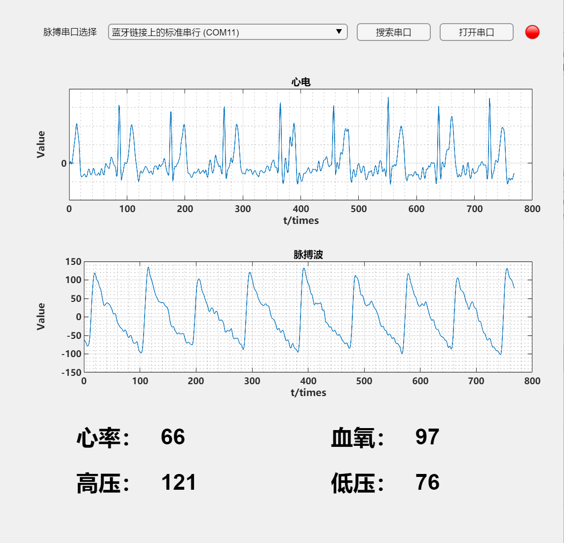
host computer program
. The host computer is written in MATLAB. Specifically, it opens the serial port to receive data sent by the microcontroller, segments it, and displays ECG and PPG separately in the coordinate area, while simultaneously displaying heart rate and blood oxygen saturation in real time. Subsequently, the two physiological signals are filtered to eliminate unwanted interference and correct baseline drift. Finally, the systolic and diastolic blood pressure are calculated using a linear fitting formula and displayed along with heart rate and blood oxygen saturation. The program code for this part will not be explained in detail here; please refer to the attached "Host Computer.zip" for details. The host computer interface is shown in the following figure:
Physical Demonstration
PCB (Unsoldered)
: The front and back of the unsoldered PCB for Version 3.0 are shown in the following figures:


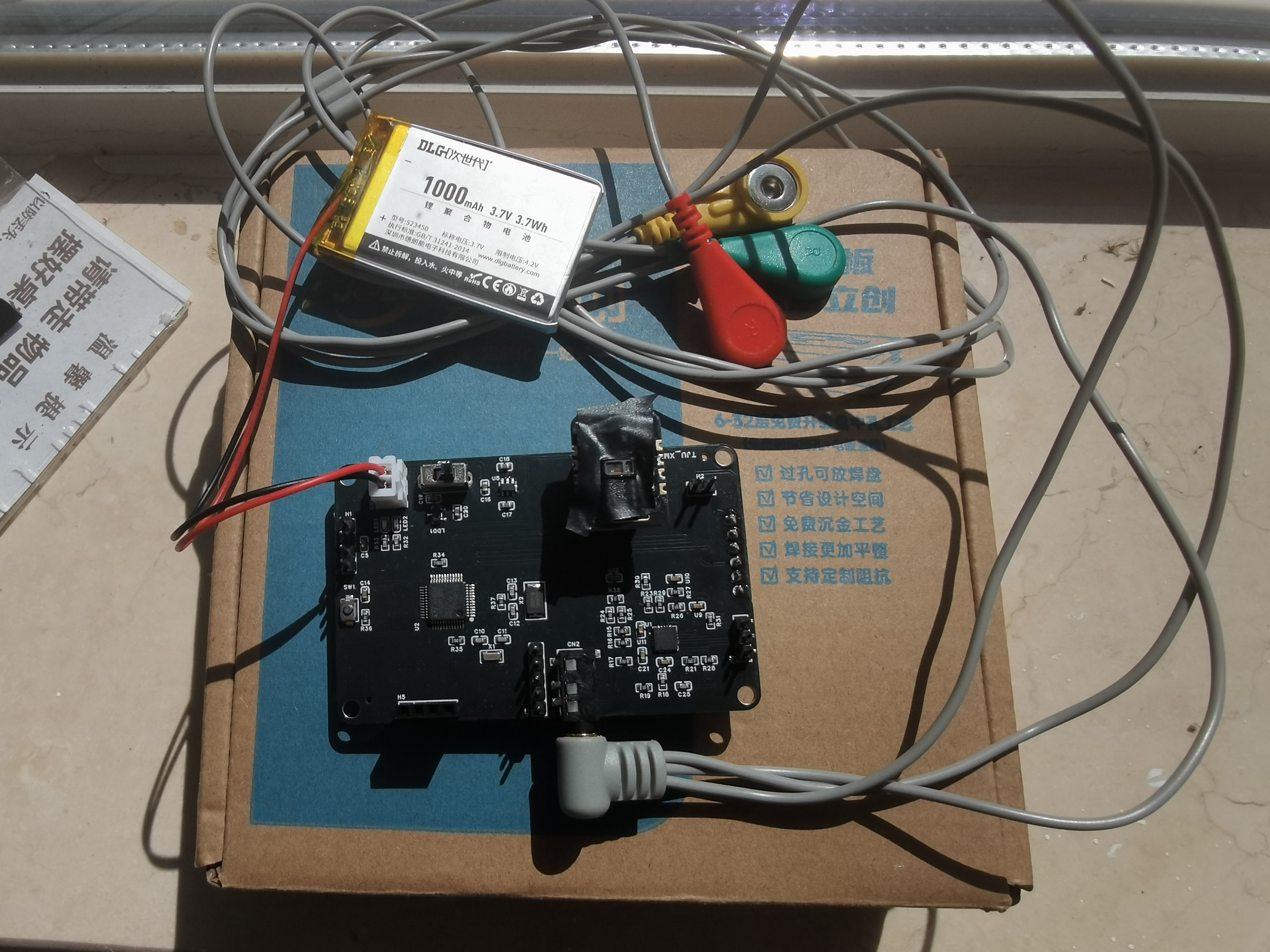
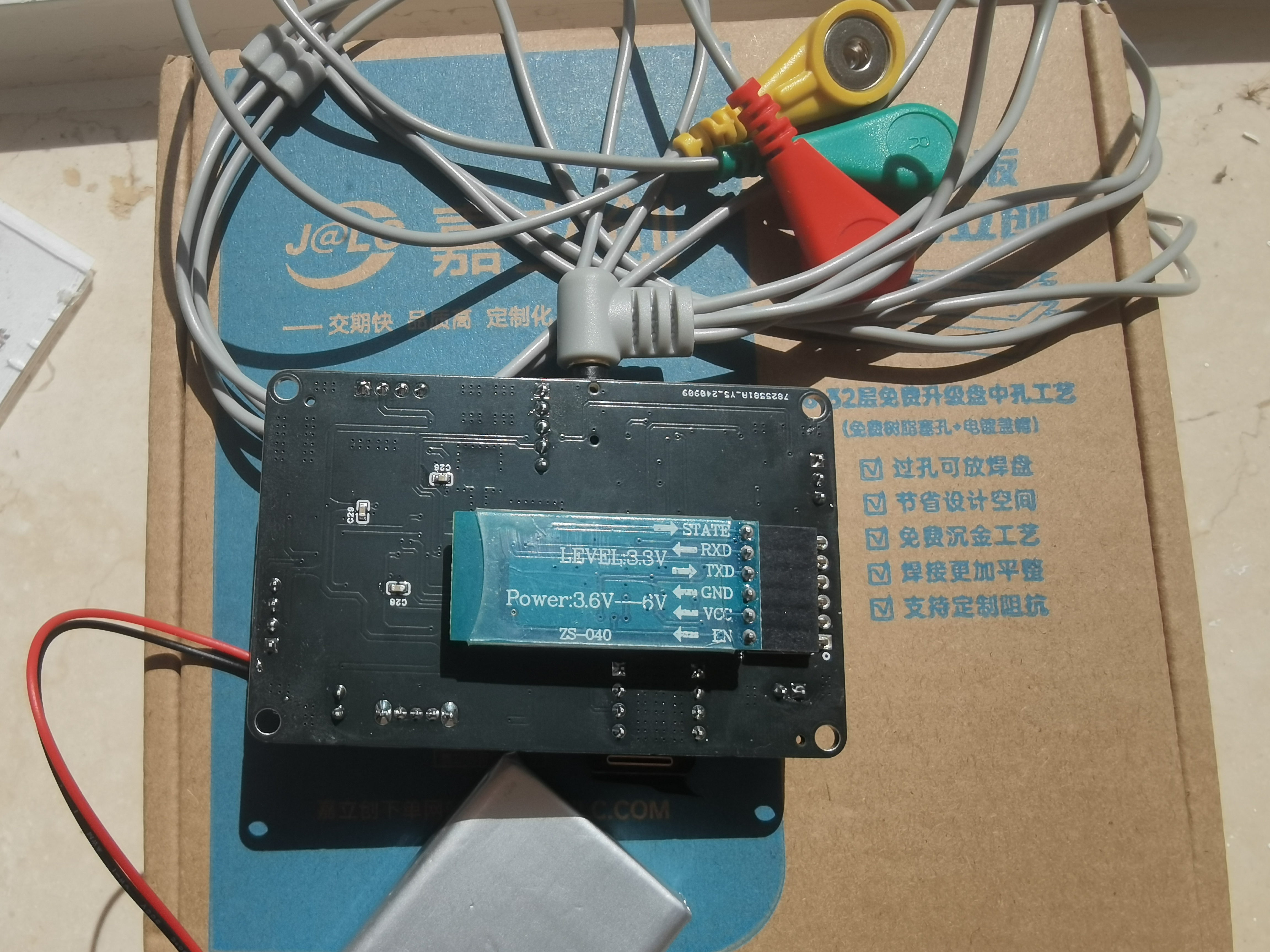
The front and back of the soldered and connected PCB for Version 3.0 are shown in the following figures:
Precautions
: 1. When soldering chips, to protect the chips, it is not advisable to use soldering temperatures above 300 degrees Celsius. The author used a 290-degree soldering iron and hot air gun for soldering, for reference only.
2. The MATLAB version used by the host computer is R2021a (64-bit).
3. Regarding the connection of the ECG lead wire, the connection of the right leg drive electrode does not necessarily have to be attached to the right leg; it can also be attached to the left or right arm.
4. When the MAX30102 is running, the index finger may touch the circuit components carrying electrical signals when in contact with it, which may affect the acquisition of ECG signals. Therefore, it is recommended to use insulating tape to seal the front of the MAX30102, leaving only the central LED exposed, to ensure that the index finger will not touch the circuit when placed on the LED.
Special Note!
This open-source project has three PCBs. The Origin board, which is the Version 1.0 PCB, is only used as a raw record. The PCB routing has major problems and cannot be used. The Version 3.0 PCB has a complete routing and has been successfully verified, achieving the preset effect. The Version 4.0 PCB has adjusted the display direction of the OLED screen based on the Version 3.0 and added a spare AD8232 connection module, but it has not been physically verified.
If you need to replicate, please use Version 3.0 directly. This version has passed physical verification.
If you have any questions, please leave a comment or contact us at 1537361071@qq.com.
The demo
video is too large; please go to Bilibili and search for BV number: BV1GKxHezEDL, or click the following link:
[https://www.bilibili.com/video/BV1GKxHezEDL/?vd_source=1b18a7fc920a520baa9888edc088f105]
Instructions:
After burning the program, disconnect the programmer, connect the 3.7V lithium battery and other modules, and turn on the switch. The red LED power indicator on the PCB will light up, indicating successful startup.
Turn on your computer's Bluetooth and connect it to the HC-05 Bluetooth device. Connect the ECG lead wire and attach the electrode patches. Place your finger on the LED light of the MAX30102 and remain still. After opening the host computer, select the corresponding Bluetooth serial port, click "Open Serial Port," and wait for the system response. The host computer will automatically detect whether the acquisition is complete and stop. No additional operation is required from the user. After the signal is collected, it will automatically calculate and display the filtered waveform and the blood pressure calculation result.


 京公网安备 11010802033920号

 Q302018PCI


