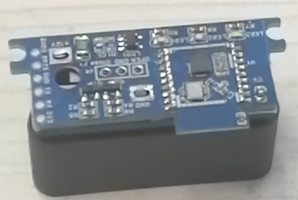
It uses readily available Bluetooth modules, along with an OBD connector and a small amount of peripheral circuitry, to enable keyless and contactless car entry. It's very convenient, eliminating the need to carry keys anymore, and the cost is only a few dollars.
Video Link:
[Ultra-Low Cost Keyless Entry Solution - Bilibili] https://b23.tv/9P4YBhL
Project Introduction:
Utilizing readily available Bluetooth modules, along with an OBD connector and minimal external circuitry, this solution enables keyless entry into your car. It's incredibly convenient, eliminating the need to carry keys, and costs only a few dollars.
Project Function:
Keyless car entry. Simply bring your phone to open or close the car door. Keep your phone in your pocket with Bluetooth enabled; no need to take it out.
Project Parameters
: 1. Bluetooth Version 5.1
2. Standby Power Consumption: 500uA
3. Power Supply: OBD constant power supply
4. Bluetooth Distance: 30m
5. Indicator Lights: Yes. White indicates connection status, green is the unlock signal, and red is the lock signal.
6. OBD Connector Voltage: 12V/24V. Purchase according to your vehicle's OBD voltage.
7. Input Voltage Range: 4-25V
Principle Analysis (Hardware Description)
: The Bluetooth module detects the signal strength between the device and the phone. When the signal is stronger than a set value, the car key sends a signal to unlock the door; when it is weaker than a set value or disconnected, the car key sends a signal to lock the door. Both the car key and the module remain inside the car at all times. No
software code
is available; debugging via WeChat mini-program is sufficient .

Precautions:
1. Before replicating, confirm whether your vehicle supports continuous OBD power supply (i.e., the OBD should always have voltage even after the car is turned off). You can check online or ask a 4S dealership.
2. Confirm the vehicle's OBD voltage. Generally, there are 12V or 24V options. Purchase a compatible OBD connector after confirming the voltage.
3. Confirm whether your car model's key can normally send and receive lock and unlock signals when inside the car, as some models have key detection and cannot lock the car if the key is inside.
4. Replicating is recommended only if you have some electrical knowledge and hands-on skills. If you lack experience, you can buy a cheap one online for a few hundred yuan, which is very convenient.
Assembly process
: 1. Solder the circuit board
; 2. Connect the key circuit board
; 3. Power on and test;
4. Assemble the outer casing
; 5. Insert it into the car;
6. Test with a mobile phone. (
Actual product image)

Keyless entry project design documents 20240923.rar
PDF_【Open Source】Ultra-Low Cost Seamless Car Entry Solution.zip
Altium [Open Source] Ultra-low Cost Seamless Car Entry Solution.zip
PADS - [Open Source] Ultra-Low Cost Seamless Car Entry Solution.zip
BOM_【Open Source】Ultra-Low Cost Seamless Car Entry Solution.xlsx
92038
NE555 Electronic Keyboard
The NE555 chip is a classic integrated circuit commonly used in applications such as timers, pulse generators, and oscillators. Its versatility makes it very popular among electronics enthusiasts and engineers. This project is a simple electronic keyboard built using the NE555 chip.
The NE555 chip is a classic integrated circuit commonly used in applications such as timers, pulse generators, and oscillators. Its versatility makes it popular among electronics enthusiasts and engineers. Below is a brief introduction to building a simple electronic keyboard using the NE555 chip.
NE555 Chip Introduction :
The NE555 chip is a timer IC introduced by Signetics (now NXP) in 1972. It features highly stable time delay capabilities and can be used as a pulse generator or oscillator. Its basic functions include monostable and bistable modes, and the output frequency and pulse width can be adjusted as needed.
Basic Principles of Building a Simple Electronic Keyboard :
The simple electronic keyboard, based on the NE555 chip, can generate sound signals of different frequencies using its oscillator mode, thus simulating different pitches. By adjusting the resistance and capacitance values of the NE555 chip, different frequency pitches can be achieved.
Materials List:
NE555 chip x1,
Resistors (various resistance values)
, Capacitors (various capacitance values)
, Buzzer or Speaker,
Key
Circuit Design,
NE555 Chip Configuration
: Configure the NE555 chip to oscillator mode (also known as square wave generator mode).
Connect the power supply to pin 8 (VCC) and pin 1 (GND) of the NE555 chip.
To set the oscillation frequency,
connect a capacitor (C1) between pins 6 and 2 of the NE555; this determines the oscillation frequency.
The pitch can be adjusted by changing the resistors (R1) between pin 7 (discharge pin) and pin 6, and (R2) between pin 6 and pin 2. A potentiometer can be used instead of a fixed resistor for pitch adjustment.
To output sound
, connect pin 3 (output pin) of the NE555 chip to the positive terminal of a buzzer or speaker.
Connect the negative terminal of the buzzer or speaker to ground (GND).
Experimental Procedure:
Connect the components of the NE555 chip according to the circuit diagram.
Adjust the resistance values using the buttons and observe the changes in the sound emitted by the buzzer to achieve different pitches.
Multiple such circuits can be designed, and different circuits can be switched using buttons to simulate a simple electronic keyboard.
Debugging and Improvement
: Adjusting the pitch: Different pitches can be obtained by adjusting different resistor values.
Sound Effects: Experiment with adding filters or modulation circuits to the buzzer or speaker to achieve richer sound effects.
Expanded Functionality: Add more buttons, each connected to a different NE555 circuit, to achieve multi-tone keyboard effects.
Summary:
Building a simple electronic keyboard using the NE555 chip is a fun and educational project. By adjusting resistors and capacitors, you can create various pitches and experience the joy of electronic music. This project also provides a good practical opportunity to learn and master basic electronic circuit design.
PDF_NE555 Electronic Keyboard.zip
Altium_NE555 electronic keyboard.zip
PADS_NE555 Electronic Keyboard.zip
BOM_NE555 Electronic Keyboard.xlsx
92039
The Magic Wand v0.8
This is a circuit design for making magic wand toys. It can also be used as a development board with a wide range of integrated peripheral functions.
Magic Wand Project Functions:
Wand Mode: Users wave the wand to perform specific actions and recite spells (optional). The wand then controls home appliances via infrared remote control, simultaneously playing sound and light effects. The LCD displays the recognized graphic shape and related prompts.
Prophet Mode: Users press a button, speak their desired topic, and release the button. The wand connects to a large language model, acquires its output, converts it into speech, and plays the speech to the user. The LCD displays the prophet's image.
BLE Air Mouse: Simulates a BLE mouse device to control a TV or computer. The middle button is used for single or double clicks, and the up, down, left, and right buttons are used for auxiliary directional control.
Night Light: Automatically turns on LED lights when the illuminance is below a certain threshold and there is activity. The MCU operates in ULP ultra-low power mode throughout the process.
Automatic Lighting: Automatically turns on home lights via infrared remote control when the illuminance is below a certain threshold and there is activity (lights must support infrared remote control).
Wand: Waving the wand displays the selected graphic or text on an LED strip. Graphic or text styles can be automatically obtained by the MCU from the network (and the resolution is automatically reduced to suit the density of the LED strip).
Intercom mode: Two wands can communicate via voice over a 2.4G Mesh network.
Configuration mode: Connect to the MCU's Wi-Fi access point, open the specified address in a browser, and configure the specific parameters of the above functions through the web interface.
Voice control: Most of the above functions support voice control. The LCD will prompt the user with voice commands as needed.
Hardware Function Verification Status:
Main
Electronic Modules
Verification Completed
More Description:
Motion Perception
MPU6050
Yes
Voice Playback
ES8311, AW8010B
Yes Can
play MP3 files stored in Flash or MP3 data streams downloaded from the network
Voice Input
ES8311, ZTS6117 Yes
Used
for voice command recognition
Infrared Control
IR940F3
No (This circuit was verified using other models in the previous version)
Used to control the switching of home appliances
Infrared Receiver
DY-IRMHA384-T05-2KB
No
(This circuit was verified using other models in the previous version)
Used to learn infrared remote control commands for home appliances
LED Light
F8MM The 0.75W light source
is
used as a flashlight or night light.
The WS2812B LED strip
is
used to display light and shadow effects . The PT550F3
ambient light sensor is used to prevent daytime illumination in night light mode. The GMT128-01 (round screen) LCD display is used to display system status, animated characters, text, etc. The MG58F18 human presence sensor is used to automatically wake the wand when it is near, and to automatically turn on the light in night light mode. The five-way button has the middle button connected to GPIO0; it can be used as a BOOT button during startup, and its function is defined according to the wand mode during normal operation. The up, down, left, and right buttons use an ADC for input detection, and their functions are defined according to the wand's operating mode. The BLE air mouse ESP32S3R8 is a prophetic mode ESP32S3R8. The W25Q256JVEIQ is used for chatting with large language models. Battery voltage detection is used to report battery voltage. This version has an issue: the installation orientation of the human presence sensing radar module does not conform to the housing design requirements. External pull-up or pull-down resistors are not designed for the GPIO used to wake the MCU from deep sleep (to further reduce current during deep sleep).
PDF_The Magic Wand v0.8.zip
Altium_Magic Wand v0.8.zip
PADS_Magic Wand v0.8.zip
BOM_The Magic Wand v0.8.xlsx
92041
Human body sensing environmental detection exhaust fan
I built my own exhaust fan for the dormitory toilet. The system includes: a lithium battery, a control board and expansion board, and a PWM fan. It has the following functions: PWM fan speed measurement, PWM fan speed control, lithium battery voltage detection, temperature and humidity detection, ammonia concentration detection, and OLED information display.
I built my own exhaust fan for a dormitory toilet. Its main function is to detect the toilet environment and whether anyone is in the room, thereby controlling the fan speed to achieve fully automatic intelligent ventilation. The
system consists of
an Arduino UNO R4 control board,
a self-made expansion board
, a lithium battery,
a PWM fan, and is shown in the physical demonstration.

PDF_Human Body Sensor Environmental Detection Exhaust Fan.zip
Altium_Human Body Sensor Environmental Detection Exhaust Fan.zip
PADS_Human Body Sensor Environmental Detection Exhaust Fan.zip
BOM_Human Body Sensor Environmental Detection Exhaust Fan.xlsx
92042
Wireless dry contact switch
The button action is triggered by connecting an optocoupler solid-state relay (PhotoMOS) via a wireless WiFi module (ESP-12S).
The switch button is controlled by connecting an optocoupler solid-state relay (PhotoMOS) via a wireless WiFi module (ESP-12S).

PDF_Wireless Dry Contact Switch.zip
Altium Wireless Dry Contact Switch.zip
PADS Wireless Dry Contact Switch.zip
BOM_Wireless Dry Contact Switch.xlsx
92043
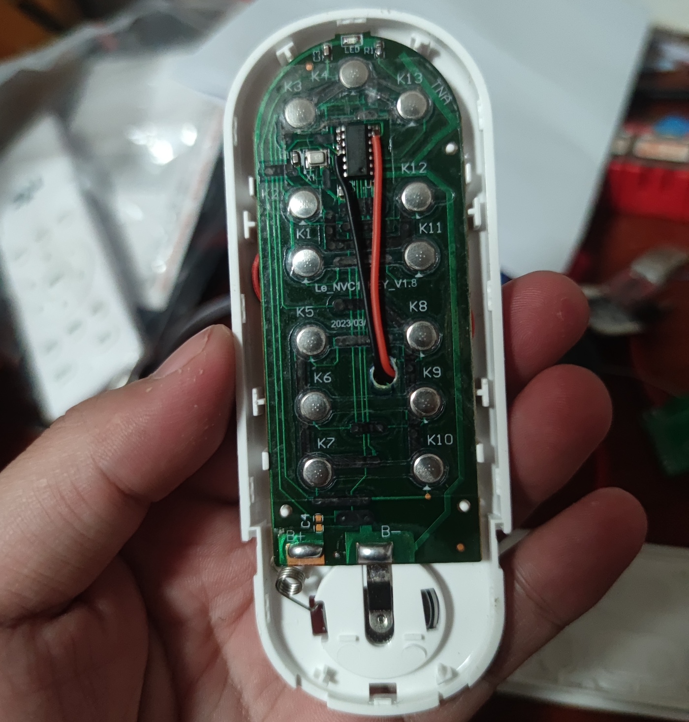
Ruler 2.0
Campus ruler of Xi'an Jiaotong University City College
The campus ruler from Xi'an Jiaotong University City College
incorporates advanced NFC technology.

PDF_Ruler 2.0.zip
Altium Ruler 2.0.zip
PADS_Ruler2.0.zip
BOM_Ruler2.0.xlsx
92044
2024 Electronic Design Contest, Problem H
2024 Provincial Competition, Problem H: Autonomous Driving Car (Sensors with MCU)
Materials:
1. Liangshanpai development board
2. Ganwei grayscale sensor, Weite JY61P angle sensor
3. 0.96-inch OLED, JY-31 Bluetooth sensor, active buzzer, LED lights and buttons
4. 12V to 5V and 5V to 3V step-down modules, DC interface and single-pole double-throw switch
5. TB6612 motor drive module, motor interface female connector, car frame and MG513X motor
connection instructions:
After soldering the female connector according to the PCB board, insert each module. See the attached notes for details.
Car function:
Implement angle closed-loop control and tracking function according to the requirements of the 2024H question in the attached document (the extended Bluetooth is configured but the control command is not written).
Operation instructions:
There are 3 operation buttons: the reset button on the development board is the reset button, the key up button on the development board is the task selection button, and the SW2 button is the motor start button.
The OLED displays the following:
Angle (current angle)
, left wheel odometer, right wheel odometer,
average odometer;
and key (corresponding key value for the task).
For question 2, at the beginning, the car should be placed perpendicular to the AB line, then the reset button should be pressed, and then it should be placed back at the starting point. At the starting point, place it until the Angle display on the OLED is approximately +90, then start the operation. This is to prevent angle jumps during gyroscope closed-loop control.
Questions 3 and 4 are similar: place the car perpendicular to the AB line, press the reset button, then place it back at the starting point. At the starting point, place it until the Angle display on the OLED is approximately +53, then reset and start the operation.
H-question_Autonomous Driving Car (1).pdf
Fourth Question Video.mp4
2024 H.zip
Comments.png
PDF_2024 Electronic Design Contest H Problem.zip
Altium_2024 Electronic Design Contest H Problem.zip
PADS_2024 Electronic Design Contest H Problem.zip
BOM_2024 Electronic Design Contest H Problem.xlsx
92046
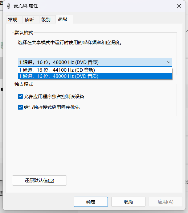
USB sound card device
This USB sound card device, built using the GPD8106, supports audio output, microphone input, and button control.
The GD108B is a USB stereo audio single-chip designed specifically for USB headset devices.
It features a crystal-free design, eliminating the need for an external crystal oscillator and saving on BOM costs. Its SOP16 package simplifies PCB design.
It includes a dual-channel high-resolution DAC and a mono ADC, along with a built-in microphone booster.
Driver-free, plug-and-play, and compatible with Windows, Android, and Linux.


GPD8106B Specification Sheet.pdf
PDF_USB sound card device.zip
Altium_USB sound card device.zip
PADS_USB sound card device.zip
BOM_USB sound card device.xlsx
92047
air001 main controller LED/PWM capture
Capture the PWM signal from the LED or pin and output the frequency and duty cycle information using a digital tube.
It can detect the on/off state of LEDs or changes in the voltage level of pins, calculate the event frequency and duty cycle, and display the results on a digital tube.
In projects where refresh rate information is needed, such as during screen refresh in a loop, but relying on UART to transmit frame rate information has a significant impact in scenarios with high speed requirements, the onboard LEDs or pins can have their voltage levels changed slightly during each loop, and the refresh rate can then be observed through this device. (Oscilloscopes or logic analyzers are optional.)
pwm_snipper.zip
PDF_air001 main controller LED-PWM capturer.zip
Altium_air001 main controller LED_PWM capturer.zip
PADS_air001 main controller LED_PWM capturer.zip
LED PWM Capturer for BOM_air001 Main Controller.xlsx
92051
electronic
 and connection diagram.
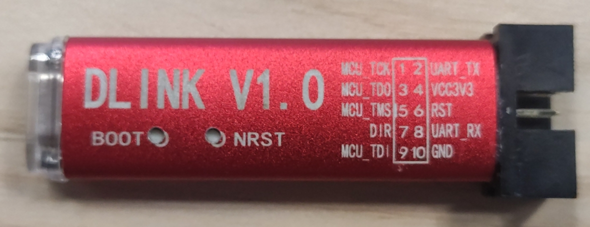
 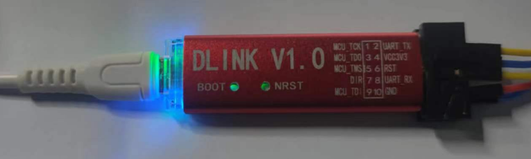 DLINK Introduction:
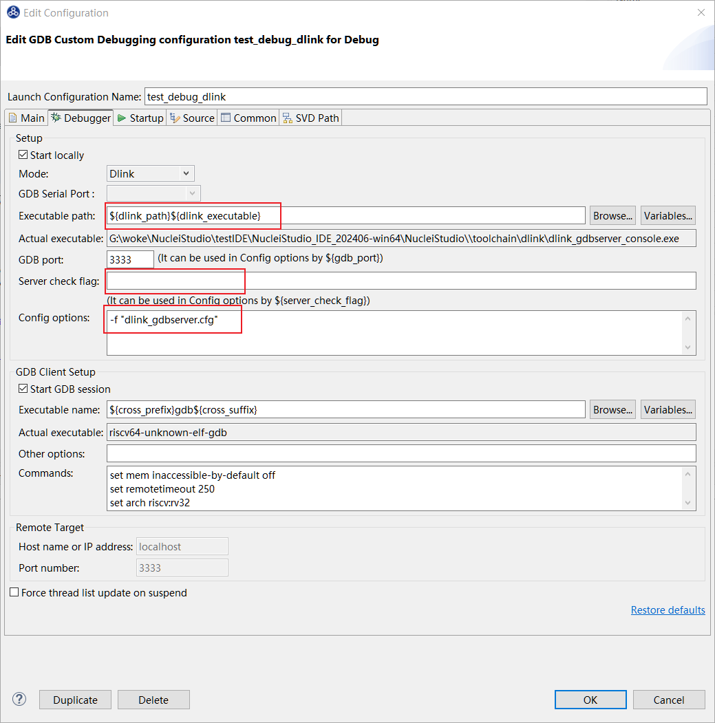
 DLINK Connection Instructions:
  Start debugging. If the configuration is correct, the Console will output as shown below, and the D-Link indicator will light up green.
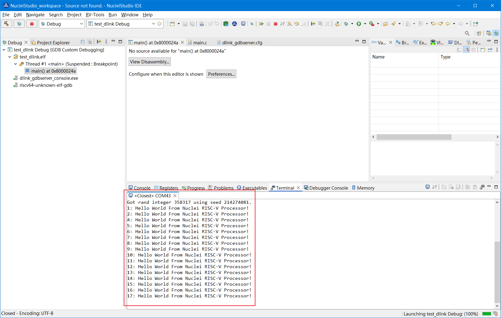


 京公网安备 11010802033920号

 RNC55K3520DPRSL


