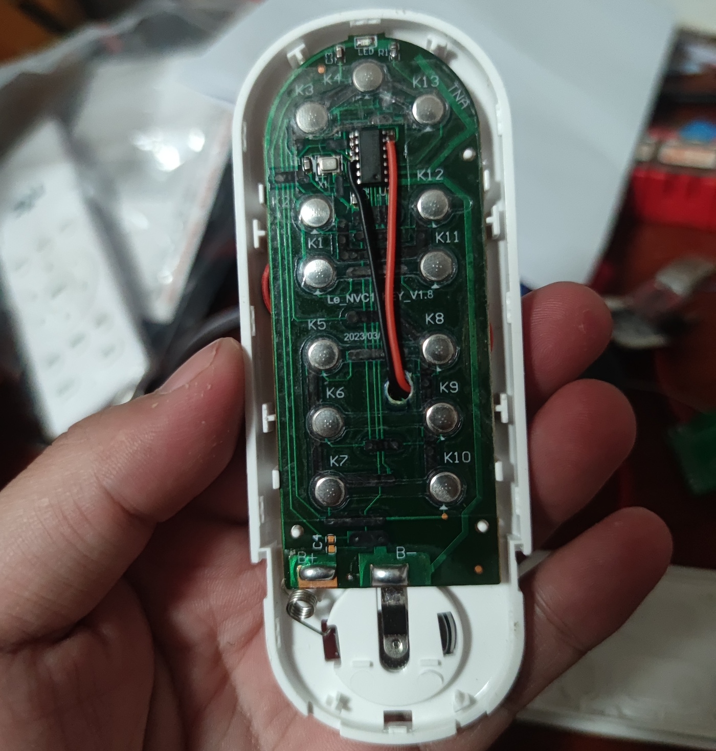
The switch button is controlled by connecting an optocoupler solid-state relay (PhotoMOS) via a wireless WiFi module (ESP-12S).
The campus ruler from Xi'an Jiaotong University City College
incorporates advanced NFC technology.

PDF_Ruler 2.0.zip
Altium Ruler 2.0.zip
PADS_Ruler2.0.zip
BOM_Ruler2.0.xlsx
92044
2024 Electronic Design Contest, Problem H
2024 Provincial Competition, Problem H: Autonomous Driving Car (Sensors with MCU)
Materials:
1. Liangshanpai development board
2. Ganwei grayscale sensor, Weite JY61P angle sensor
3. 0.96-inch OLED, JY-31 Bluetooth sensor, active buzzer, LED lights and buttons
4. 12V to 5V and 5V to 3V step-down modules, DC interface and single-pole double-throw switch
5. TB6612 motor drive module, motor interface female connector, car frame and MG513X motor
connection instructions:
After soldering the female connector according to the PCB board, insert each module. See the attached notes for details.
Car function:
Implement angle closed-loop control and tracking function according to the requirements of the 2024H question in the attached document (the extended Bluetooth is configured but the control command is not written).
Operation instructions:
There are 3 operation buttons: the reset button on the development board is the reset button, the key up button on the development board is the task selection button, and the SW2 button is the motor start button.
The OLED displays the following:
Angle (current angle)
, left wheel odometer, right wheel odometer,
average odometer;
and key (corresponding key value for the task).
For question 2, at the beginning, the car should be placed perpendicular to the AB line, then the reset button should be pressed, and then it should be placed back at the starting point. At the starting point, place it until the Angle display on the OLED is approximately +90, then start the operation. This is to prevent angle jumps during gyroscope closed-loop control.
Questions 3 and 4 are similar: place the car perpendicular to the AB line, press the reset button, then place it back at the starting point. At the starting point, place it until the Angle display on the OLED is approximately +53, then reset and start the operation.
H-question_Autonomous Driving Car (1).pdf
Fourth Question Video.mp4
2024 H.zip
Comments.png
PDF_2024 Electronic Design Contest H Problem.zip
Altium_2024 Electronic Design Contest H Problem.zip
PADS_2024 Electronic Design Contest H Problem.zip
BOM_2024 Electronic Design Contest H Problem.xlsx
92046
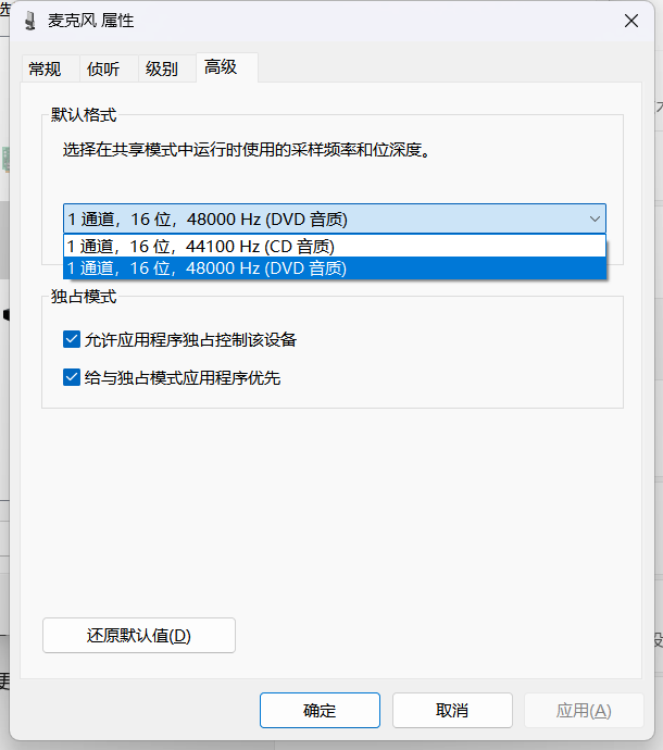
USB sound card device
This USB sound card device, built using the GPD8106, supports audio output, microphone input, and button control.
The GD108B is a USB stereo audio single-chip designed specifically for USB headset devices.
It features a crystal-free design, eliminating the need for an external crystal oscillator and saving on BOM costs. Its SOP16 package simplifies PCB design.
It includes a dual-channel high-resolution DAC and a mono ADC, along with a built-in microphone booster.
Driver-free, plug-and-play, and compatible with Windows, Android, and Linux.


GPD8106B Specification Sheet.pdf
PDF_USB sound card device.zip
Altium_USB sound card device.zip
PADS_USB sound card device.zip
BOM_USB sound card device.xlsx
92047
air001 main controller LED/PWM capture
Capture the PWM signal from the LED or pin and output the frequency and duty cycle information using a digital tube.
It can detect the on/off state of LEDs or changes in the voltage level of pins, calculate the event frequency and duty cycle, and display the results on a digital tube.
In projects where refresh rate information is needed, such as during screen refresh in a loop, but relying on UART to transmit frame rate information has a significant impact in scenarios with high speed requirements, the onboard LEDs or pins can have their voltage levels changed slightly during each loop, and the refresh rate can then be observed through this device. (Oscilloscopes or logic analyzers are optional.)
pwm_snipper.zip
PDF_air001 main controller LED-PWM capturer.zip
Altium_air001 main controller LED_PWM capturer.zip
PADS_air001 main controller LED_PWM capturer.zip
LED PWM Capturer for BOM_air001 Main Controller.xlsx
92051
electronic


 京公网安备 11010802033920号

 3SAM6014N


