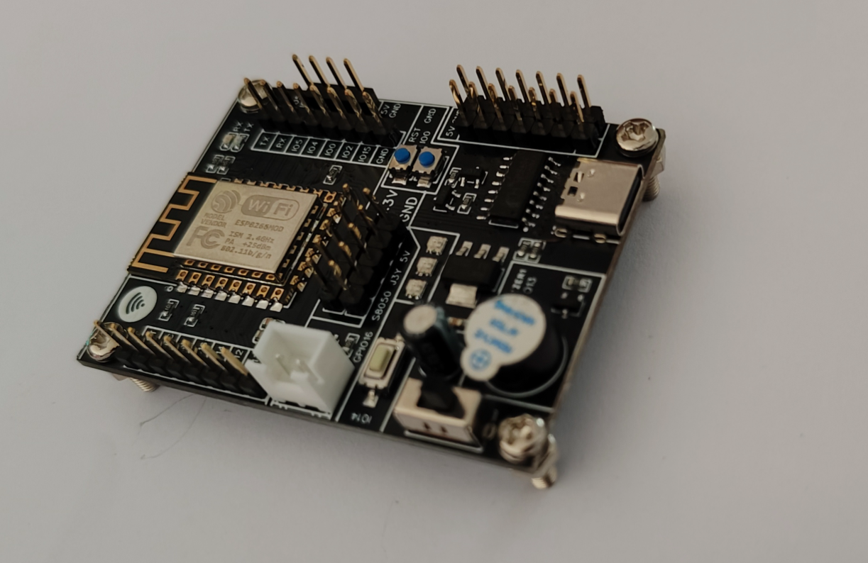
The ESP8266 IoT development board features an onboard CH340C serial port converter, automatic download, buzzer, WS2812B, transistor switching circuit, and all pins are exposed, making it suitable for learning ESP8266EX.
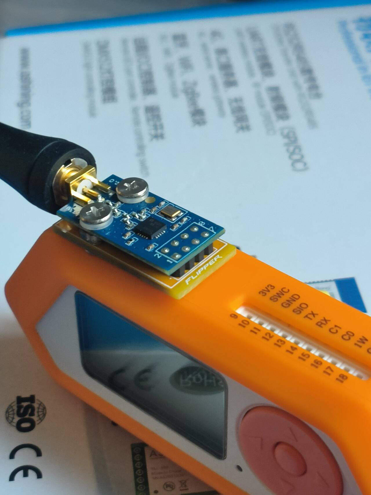
The ultra-mini module is designed independently and is universal.
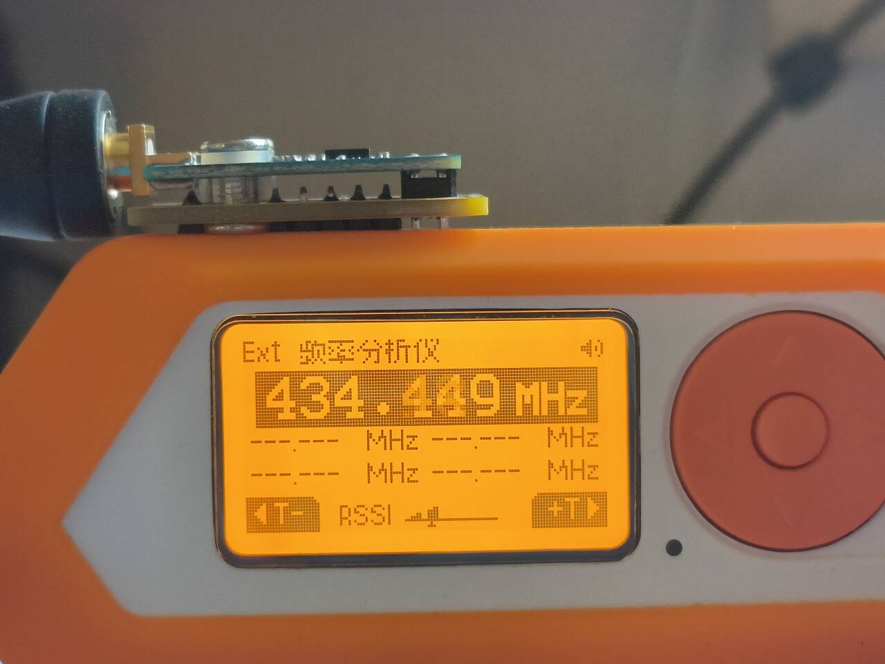
Super MINI, high-value design! Power issue fixed on 20240730.

You can purchase and use this module. Note: Use extended screws and nuts with M3 connectors. QQ group: 694517481. Join the group to discuss and download materials.
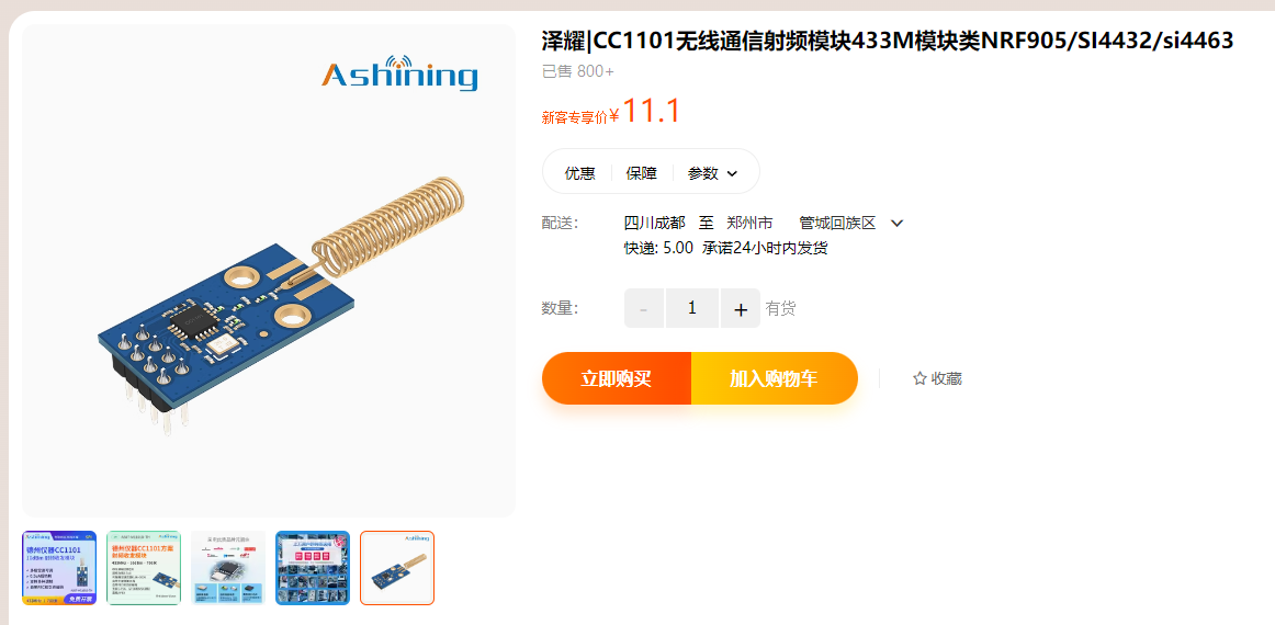


PDF_Flipperzero Little Dolphin CC1101 Expansion Board M1101D Module.zip
Altium_Flipperzero Little Dolphin CC1101 Expansion Board M1101D Module.zip
PADS_Flipperzero Little Dolphin CC1101 Expansion Board M1101D Module.zip
BOM_Flipperzero Little Dolphin CC1101 Expansion Board M1101D Module.xlsx
93421
Brushless ESC driver based on STC32G without a hall
Hardware components: The system includes an STC32G core board, a brushless ESC, a motor, and other necessary connectors and cables. The ESC receives control signals from the core board and drives the motor to rotate.
Software control: The program on the core board generates control signals that drive the motor.
1. Brushless Motor Principle and
Internal Structure: A brushless motor contains three coils (usually called phases), each connected at one end and led to the outside. Inside the motor is an internal rotor with a permanent magnet having N/S poles.
Rotation Principle: By energizing the motor in a specific sequence, the rotor can rotate. For example, applying a positive voltage to phase A and a negative voltage to phase B will cause the rotor to rotate to a certain position; changing the energizing sequence will continue the rotation.
Commutation: To maintain continuous rotor rotation, the energized coils need to be changed periodically. One revolution typically requires six commutations, each with a commutation angle of 60 degrees.
2. Hall-less Rotor Position Detection:
Traditional Methods: Rotor position detection is usually achieved using Hall sensors or magnetic encoders, but these methods increase cost or complexity.
Hall-less Method: The STC32G series drive solution uses hall-less technology, typically using zero-crossing detection or software algorithms to detect rotor position. Zero-crossing detection determines the rotor position by comparing the three-phase voltages with the motor's neutral point voltage.
3. STC32G Brushless ESC Drive PCB Motor
Hardware Components: The system includes an STC32G core board, a brushless ESC, a motor, and other necessary connectors and cables. The ESC receives control signals from the core board and drives the motor to rotate.
Software Control: The program on the core board generates control signals, which are processed by the ESC to drive the motor. The program also needs to detect the rotor position and adjust the control signals based on the detected position. PCB
Design: The PCB (Printed Circuit Board) is the foundation for connecting various hardware components. When designing the PCB, factors such as the rationality of wiring, component layout, and heat dissipation need to be considered.
July 30.mp4
Three-phase brushless motor driver - STC32G - Hallless - PID control - OLED display - Serial port drawing.rar
PDF_STC32G Hallless Brushless ESC Driver.zip
Altium-based brushless ESC driver without a HALL (STC32G) for STC32G.zip
PADS_STC32G-based brushless ESC driver without a HALL.zip
BOM_Driver for STC32G Brushless ESC without Hall.xlsx
93422
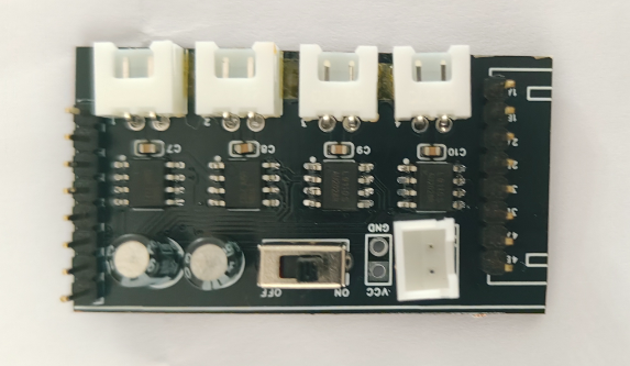
L9110 Four-Channel Motor Drive Module
L9110 Four-Channel Motor Drive Module
The L9110 four-channel motor drive module has four built-in L9110 motor drive chips, which can drive four motors.
PDF_L9110 Four-Channel Motor Driver Module.zip
Altium_L9110 Four-Channel Motor Driver Module.zip
PADS_L9110 Four-Channel Motor Driver Module.zip
BOM_L9110 Four-Channel Motor Driver Module.xlsx
93423
STC32G12K128 core board
STC32G12K128 core board, minimum system board
This core board uses the latest STC32G12K128 microcontroller with fully exposed interfaces supporting USB download.
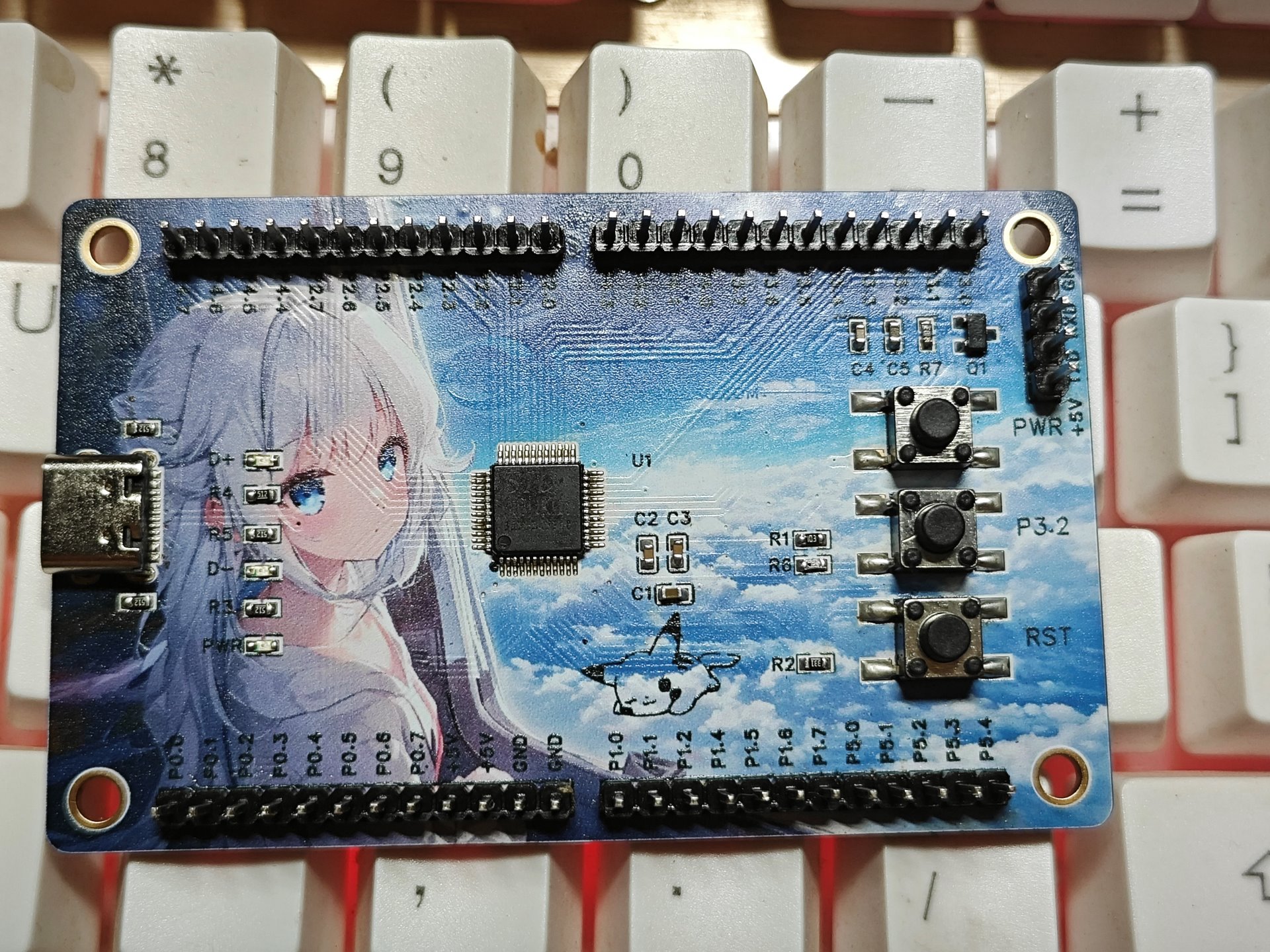
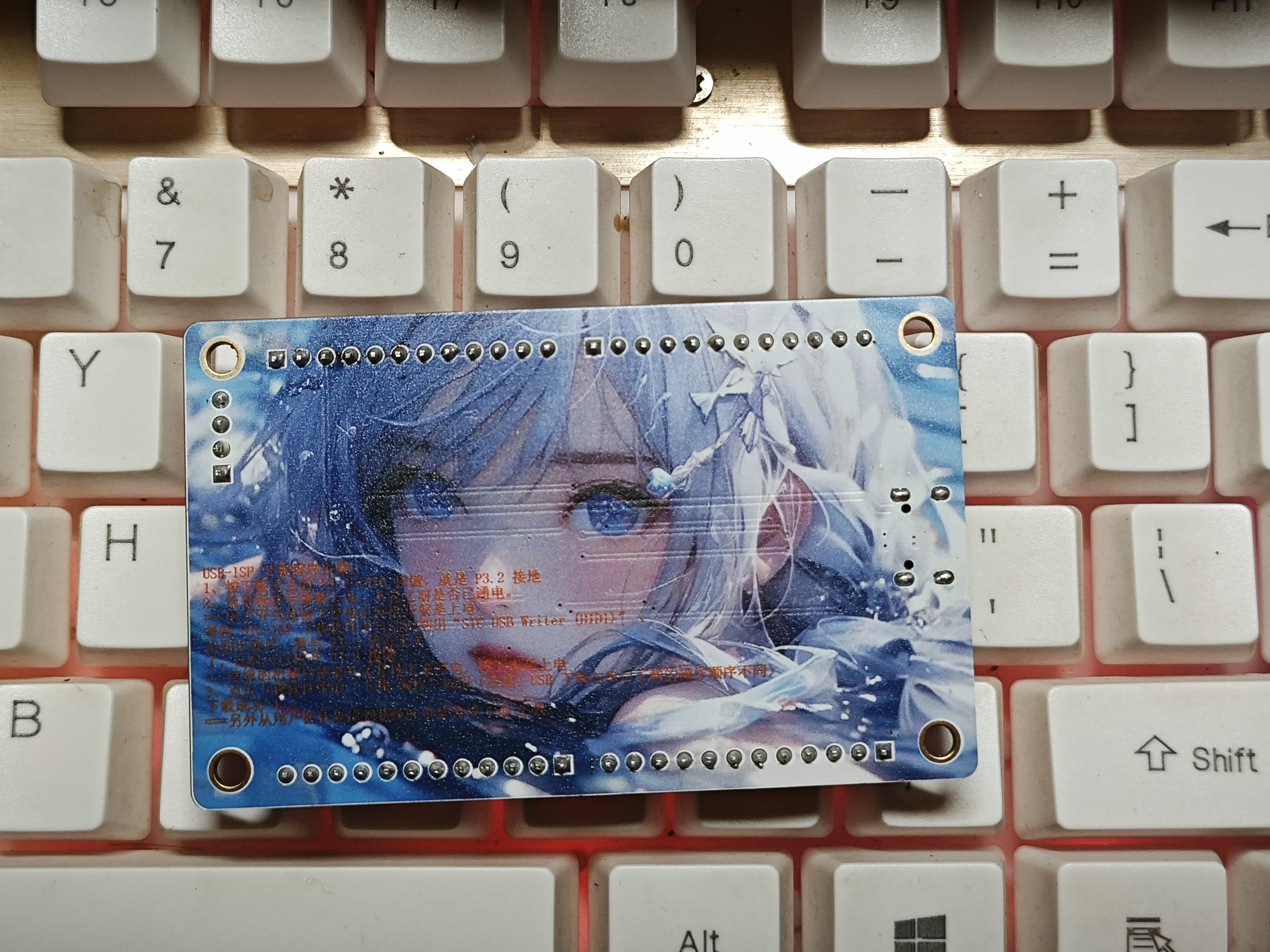
USB-ISP download steps: 1. Press the P3.2/INT0 button on the board to ground P3.2. 2. Power on the target chip, regardless of whether it was previously powered on. ===The electronic switch turns off power when pressed and powers on when released. Wait for the STC-ISP download software to automatically recognize "STC USB Writer (HID1)". Once recognized, the P3.2 status is irrelevant; you can then release the P3.2 button.===The traditional mechanical self-locking switch turns off power when pressed up and powers on when pressed down. 3. Click the "Download/Programming" button in the download software (Note: the operation sequence for USB download and serial download is different). Download successful! ===Additionally, when performing a soft reset from the user area to the system area, it also requires waiting for USB download.
Note: 1. Except for P3.0 and P3.1, all other I/O ports are in a high-impedance input state after power-on. Users must set the I/O port mode before using it. 2. All I/O ports can be set to quasi-bidirectional port mode, strong push-pull output mode, open-drain output mode, or high-impedance input mode. Each I/O port can also independently enable its internal 4K pull-up resistor. 3. When P5.4 is enabled as the reset pin, the reset level is low. 4. The ADC's external reference power supply pin, ADC_VRef+, must not be floating; it must be connected to an external reference power supply or directly to Vcc. 5. If USB download is not required, P3.0/P3.1/P3.2 must not be low simultaneously during chip reset.
lv_0_20240730203508.mp4
PDF_STC32G12K128 core board.zip
Altium_STC32G12K128 core board.zip
PADS_STC32G12K128 core board.zip
BOM_STC32G12K128 Core Board.xlsx
93424
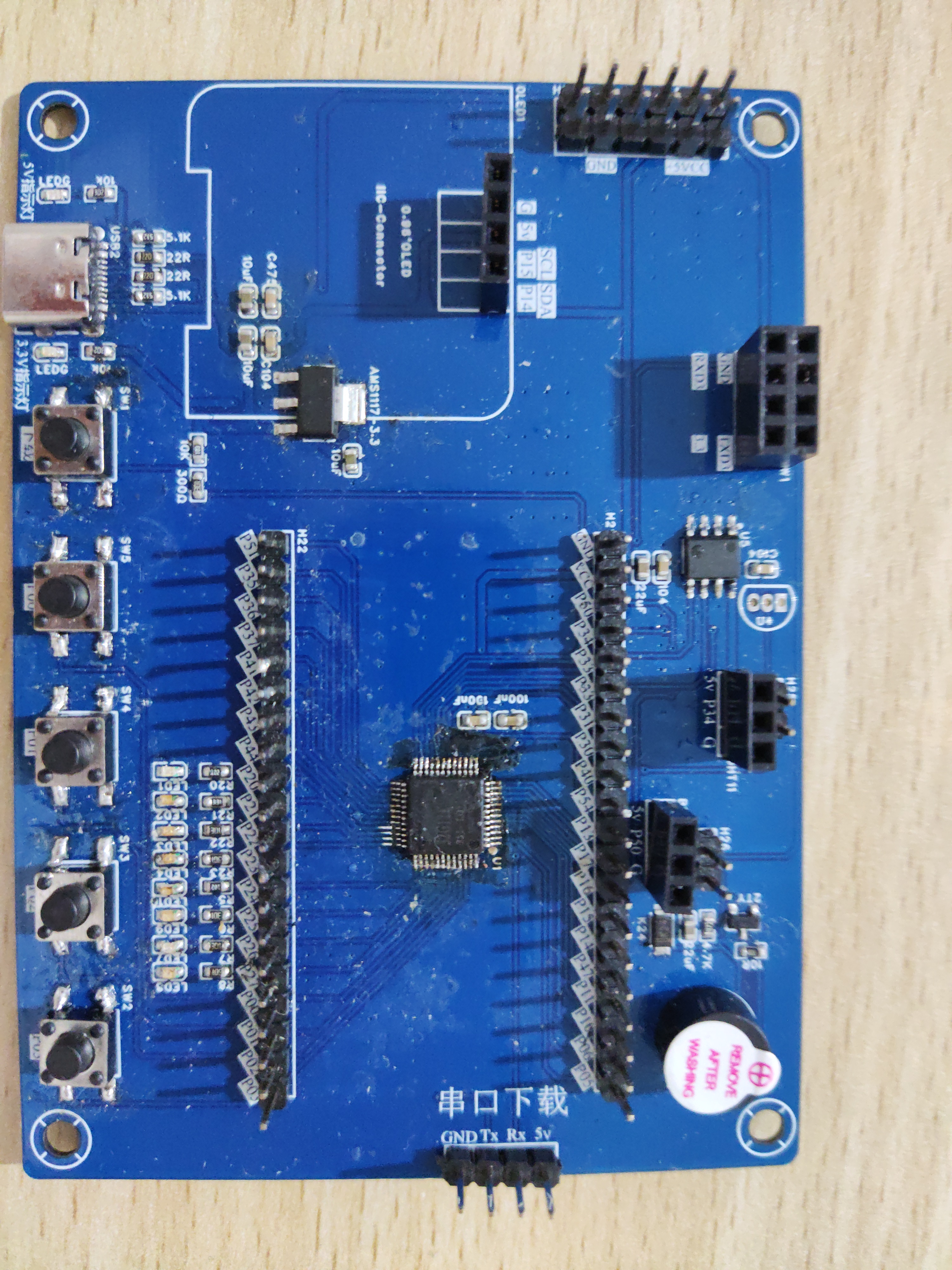
STC32_KS0108
Both development boards and engineering boards are acceptable.
The LCD controller is of the KS0108 type. The STC website has a bare-metal UGFX module. The website address is: [New Reminder] [uGFX/GUI + uC/OS-II] @STC32G; uGFX/GUI@STC32G bare-metal - uCOS/FreeRTOS, GUI-uGFX/U8g2, file system, domestic RTOS, real-time operating system. This is a global 32-bit 8051 enthusiast mutual aid and exchange community: https://www.stcaimcu.com/forum.php?mod=viewthread&tid=7130&extra=&page=1.
The network controller is W5500, with automatic RS-485 transmission and reception, TTL to USB conversion, and uses serial port 2.
Everyone can learn from it.
PDF_STC32_KS0108.zip
Altium_STC32_KS0108.zip
PADS_STC32_KS0108.zip
BOM_STC32_KS0108.xlsx
93425
electronic


 京公网安备 11010802033920号

 SHD2185B


