This is an original Type-C powered boost biasTee for powering active loop antennas. It uses a boost converter with LDO secondary regulation, followed by LC and common-mode inductor filtering before supplying power to the RF signal bias. Paired with the active loop antenna, it provides strong medium-wave and short-wave reception with minimal noise.
The default output voltage is 12V, and it works well with the open-source LZ1AQ loop antenna. The first-stage boost output is 15V, and the second-stage output is 12V. The LZ1AQ antenna has a relatively high operating current, which is normal for the LM7812. In actual testing, it operated stably for a week without interruption of power.
If you need to modify the output voltage, you can replace the LDO regulator and then modify the boost feedback resistor. It is recommended that the boost output be 2-3V higher than the regulated voltage to allow for some adjustment headroom for better power supply rejection ratio.
Open-source LZ1AQ active shortwave antenna: https://oshwhub.com/zhuxiangyu92/lz1aq-xiao-huan-tian-xian-fang-da-qi
Make your appliance storage compartment more organized;
you can easily add or remove wiring; up to 6 outputs
.
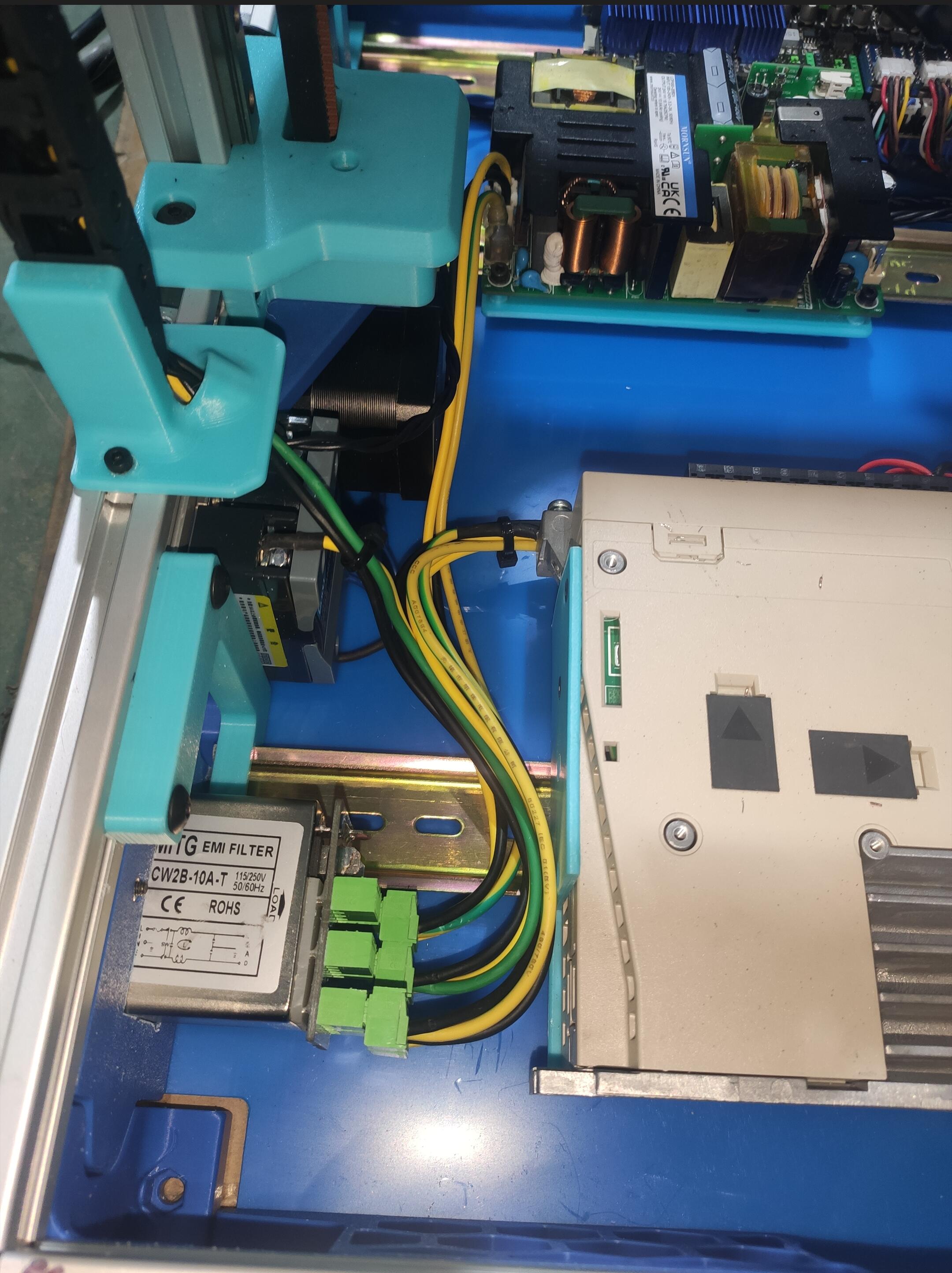
Voron2.4_power_inlet_CW2B.STEP
Trident_power_inlet_CW2B.STEP
PDF_Voron CW2B 220V Power Hub.zip
Altium_Voron CW2B 220V Power Hub.zip
PADS_Voron CW2B 220V Power Hub.zip
BOM_Voron CW2B 220V Power Hub.xlsx
92131
STC89C51 microcontroller development board
A simple 51 microcontroller development board
I designed a simple 51 microcontroller development board by drawing the circuit diagram of commercially available development boards.
---
Features:
- 7×7.3cm size, easy to carry
- Onboard running lights, digital tubes, independent buttons, buzzers, etc., suitable for learning I/O and peripheral use
- The microcontroller is in a DIP-40 package, compatible with 40-pin IC sockets or chip test sockets, facilitating chip replacement
- Designed a programming button (lower left corner), a short press of this button during programming will automatically power off and power on the chip
- Resistors and capacitors use 0805 packages, Type-C interface uses a female connector with board, easy for beginners to solder
---
Front view (initial design), the female connector and crystal oscillator capacitors have not yet arrived, so they are not soldered yet
![IMG_20240918_182300.jpg]

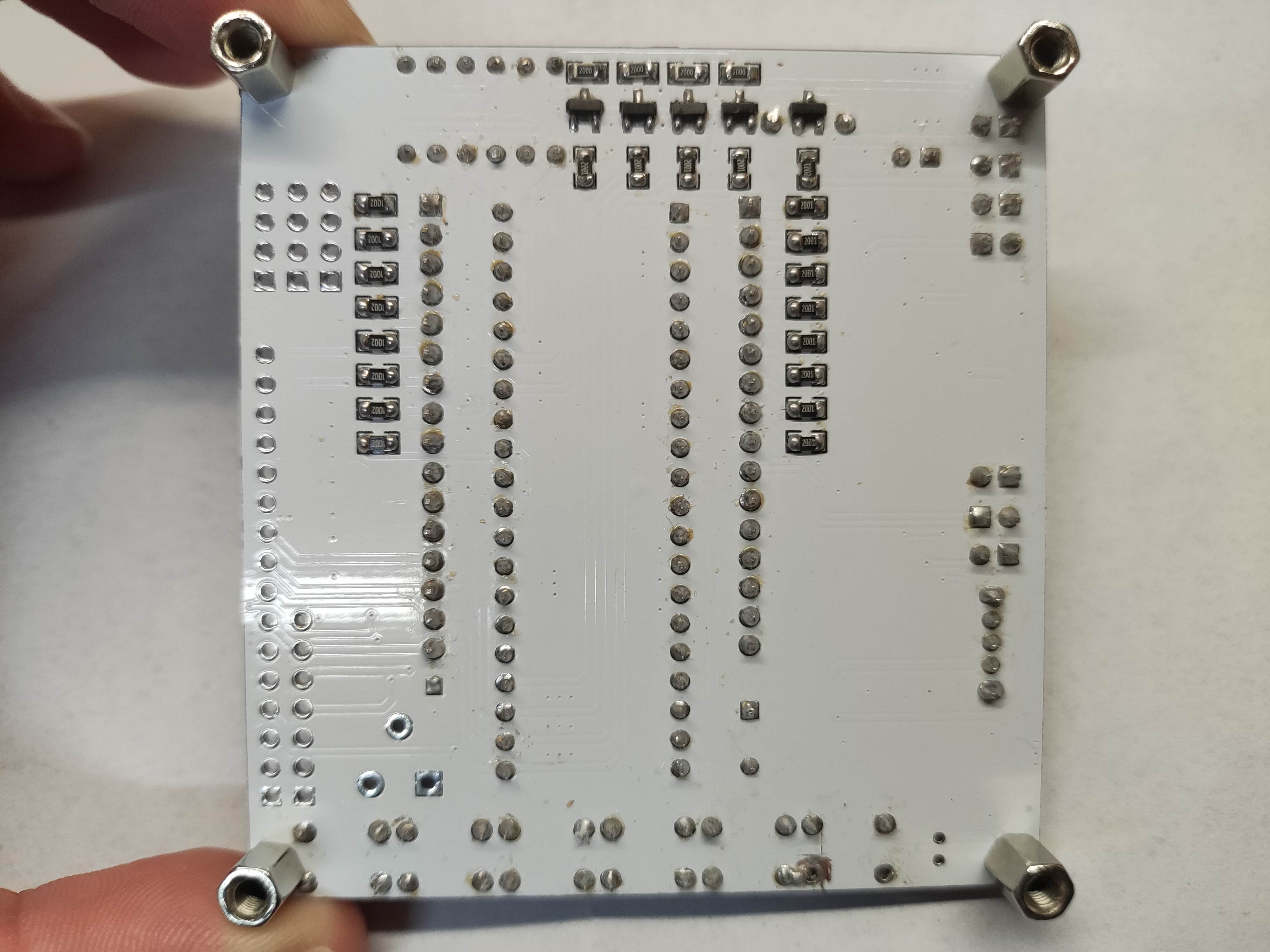
Back view
![IMG_20240918_182424.jpg]
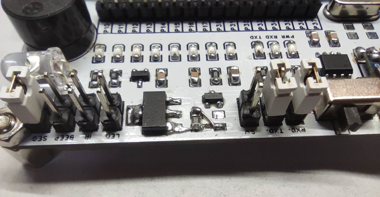
An error occurred during the design process, the conduction condition of the MOSFET was incorrect, and as a result, the automatic power-on button did not work during testing, so I had to scrape the board and add jumper wires to solve the problem. The project has been modified before release and can be used directly
! ![IMG_20240918_182343.jpg]
This is a personal creation; please feel free to discuss and correct any shortcomings.
PDF_STC89C51 Microcontroller Development Board.zip
Altium_STC89C51 microcontroller development board.zip
PADS_STC89C51 Microcontroller Development Board.zip
BOM_STC89C51 Microcontroller Development Board.xlsx
92132
ESP32-based voice-activated color light design
This project combines the powerful functions of the ESP32 microcontroller with voice recognition technology, enabling users to control the switching on and off of colored lights, adjust colors, and switch modes via voice commands, greatly enhancing the ease of use and fun.
In the context of the increasing popularity of smart homes, the ESP32 voice-activated color light design
brings new possibilities to home decoration and intelligent control with its unique interactive experience and rich color variations. This project combines the powerful functions of the ESP32 microcontroller with voice recognition technology, allowing users to control the lights' on/off status, color adjustment, and mode switching via voice commands, greatly enhancing ease of use and enjoyment.
Core components:
ESP32 Development Board: As the core control unit of the system, the ESP32 integrates Wi-Fi and Bluetooth dual-mode communication functions, as well as rich GPIO interfaces, easily processing voice recognition data, controlling light color and brightness, and supporting remote control and firmware upgrades.
Voice Recognition Module (e.g., iFlytek, Baidu Voice Recognition SDK, or a simple hardware module based on specific voice command recognition): Responsible for capturing user voice commands and converting them into text or command codes that the system can recognize, enabling human-computer interaction.
RGB LED Strip or RGB LED Beads: As the main carrier of color expression, RGB LEDs can emit red, green, and blue light. By adjusting the intensity ratio of different colors, almost any visible light color can be mixed.
Power Supply and Driver Circuit: Provides stable power to the ESP32 and RGB LEDs, ensuring the LEDs accurately display colors according to control commands.
Optional Components: Such as a megaphone for voice feedback, a microphone array to enhance voice recognition accuracy, and a housing design to protect internal circuitry and enhance aesthetics.
Features:
Voice Control: Users can achieve comprehensive control of the colored lights through simple voice commands such as "turn on the light," "turn off the light," "turn to blue," and "increase brightness."
Color Adjustment: Supports free switching and mixing of multiple colors, allowing users to adjust the light color according to their mood or ambient atmosphere.
Scene Modes: Preset multiple lighting scene modes (such as reading mode, party mode, romantic mode, etc.), allowing one-click switching to enjoy different atmospheres.
Remote Control: Combined with the ESP32's Wi-Fi function, remote control can be achieved through a mobile app or webpage, allowing users to control the colored lights in their home from anywhere.
Smart Linkage: Can be linked with other smart home devices (such as smart speakers, security systems, etc.) to achieve more intelligent home scene applications.
Application Scenarios:
The ESP32 voice-activated decorative light is suitable for various settings including living rooms, bedrooms, studies, and dining rooms. It not only serves as decorative lighting, enhancing the comfort and aesthetics of the living environment, but also brings more convenience and enjoyment to life through intelligent control. Furthermore, it can be applied to commercial displays, bars, nightclubs, KTV rooms, and other venues to create unique atmospheres and visual effects.
Language-themed Colored Night Light.mp4
Project code.zip
PDF_ESP32-based voice-activated color light design.zip
Altium_ESP32-based voice-activated color light design.zip
PADS_ESP32-based voice-activated color light design.zip
BOM_Design of Voice-Activated Colored Lights Based on ESP32.xlsx
92133
ESP32 Night Light Holder
Small IoT projects, progress through learning
Project Introduction:
ESP32S3 Night Light Box.
This project is a night light switch button control, which can also be used to control chargers and other USB devices.
Project Functions
: [This section can be filled in with relevant project functions and application scenarios.] Example:
It has one independent button used to locally light up and turn off the relay, thereby controlling the USB socket's power supply.
Principle Analysis (Hardware Description):
The pins, through optocouplers and transistor amplification, deliver the required voltage and current to the relay, thus driving the relay to engage and complete the conduction between the USB sockets.
Software Code:
Refer to the LCSC ESP32S3 development board example program. The button lights up the LED. The 48-pin configuration was modified to 38 pins. Originally,
the plan was to make it Wi-Fi-enabled LED lighting, but the relay encountered many problems, causing a long delay. Therefore, the button lighting was used first.
f7fc3389b4b20e6dbebd3592b391b260.mp4
PDF_esp32 Night Light Holder.zip
Altium_esp32 night light holder.zip
PADS_esp32 Night Light Holder.zip
BOM_esp32 Nightlight Stand.xlsx
92134
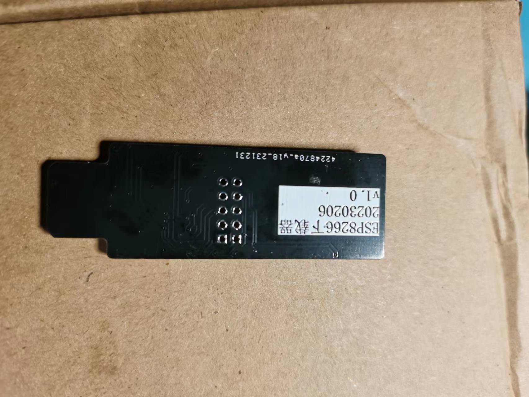
ESP8266 downloader, with corresponding materials to be updated later.
An ESP8266 downloader and development board that does not require a USB connector
An ESP8266 downloader and development board that does not require a USB connector


PDF_ESP8266 downloader, with subsequent updates of corresponding materials.zip
Altium_ESP8266 downloader, with subsequent updates and related materials.zip
PADS_ESP8266 downloader, with subsequent updates to the corresponding materials.zip
Downloader for BOM_ESP8266, with corresponding updated materials in .xlsx format.
92137
electronic
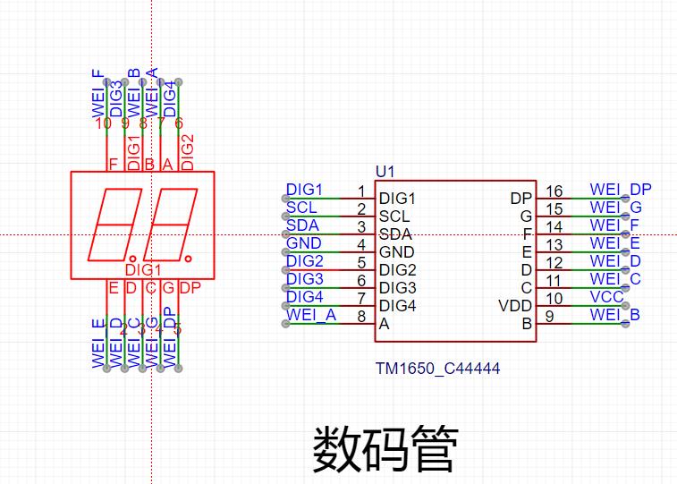 It employs three sets of LEDs (red, yellow, and green), connected in a three-series, three-parallel configuration, with each set connected in series with a 100Ω resistor for current limiting. Considering the different current requirements of the red, yellow, and green lights, different resistors are used, connected in series in their respective branches. The brightness can be uniformly adjusted later. Simultaneously, each color LED is strung together
 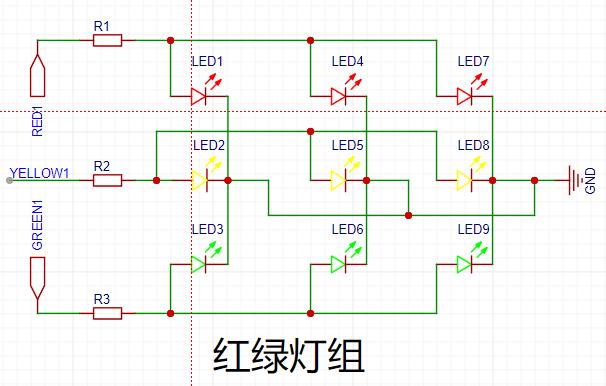 using a 24-pin interface and the baseboard (development board) for communication, which can meet general needs.
 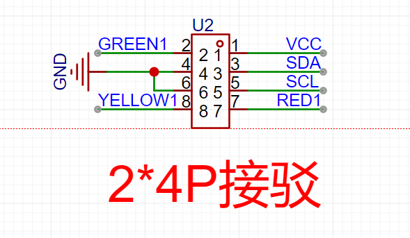 ...
... 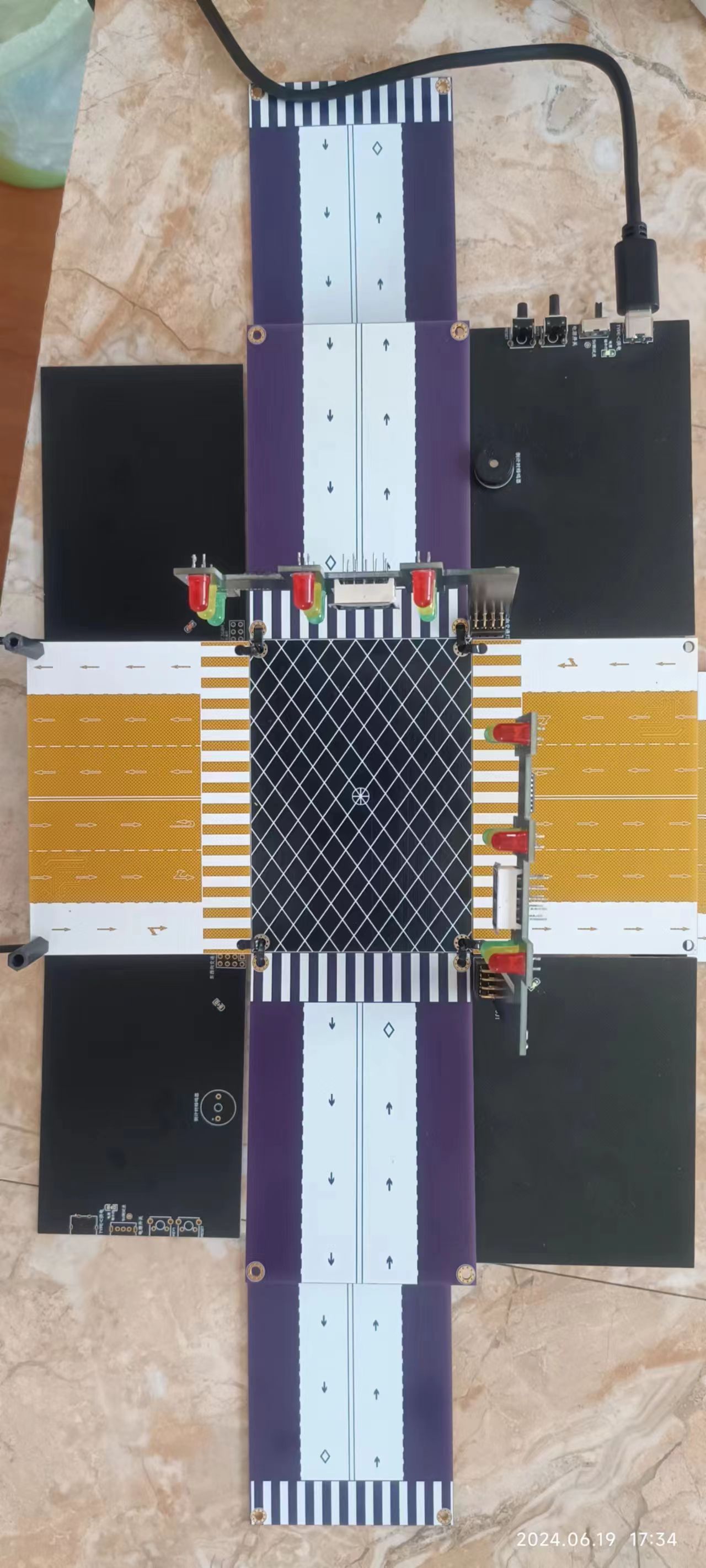 Figure 2: Side view;
 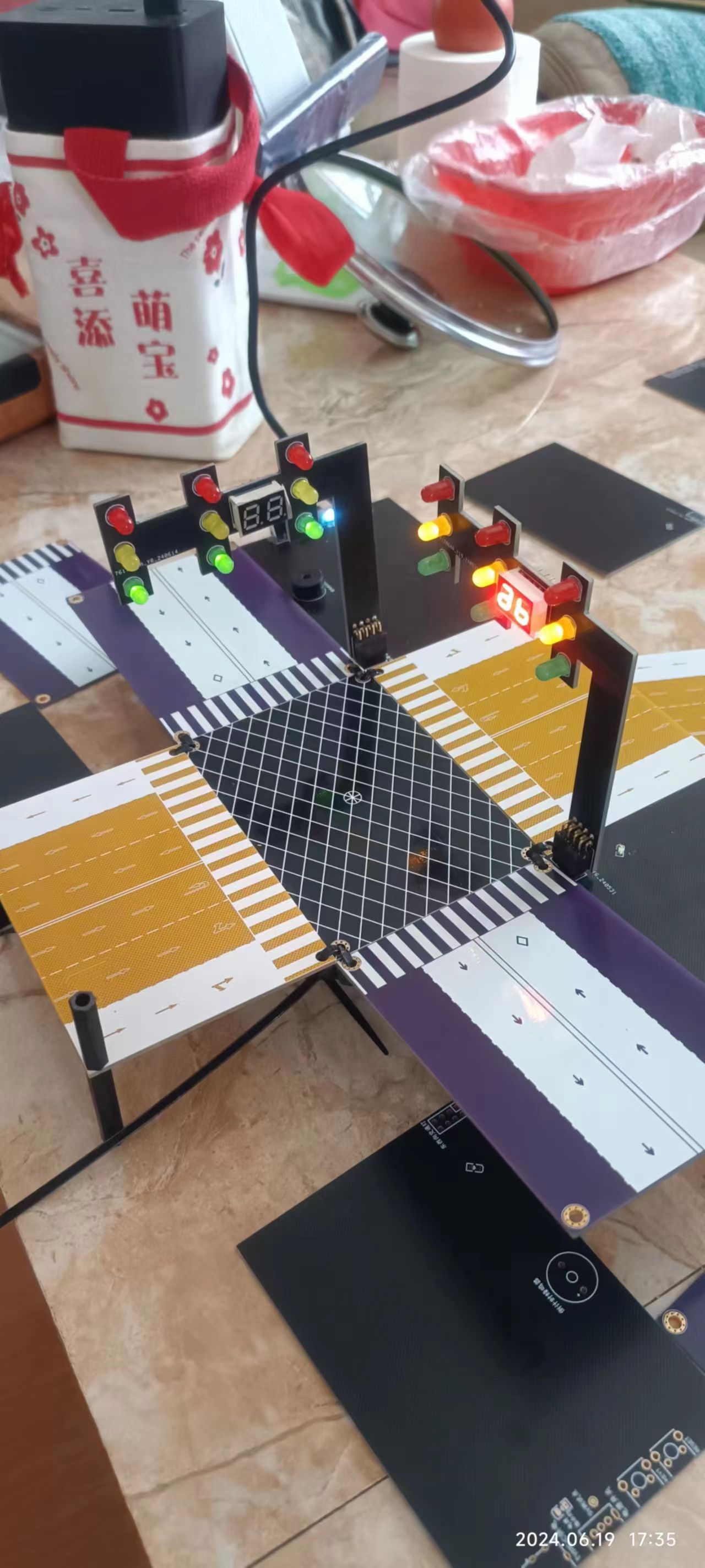 Figure 3: Debugging interface board
 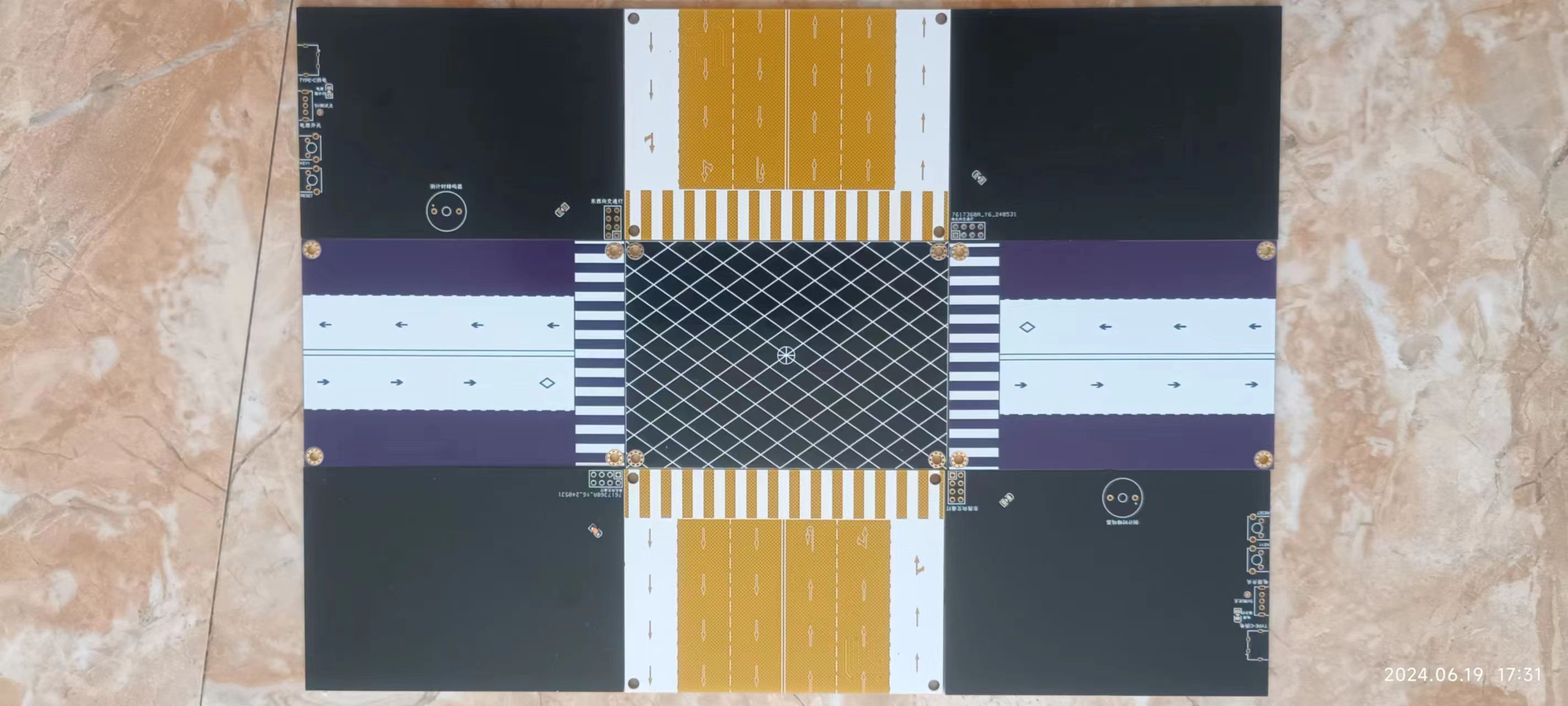 ; Figure 4: Traffic light board;
 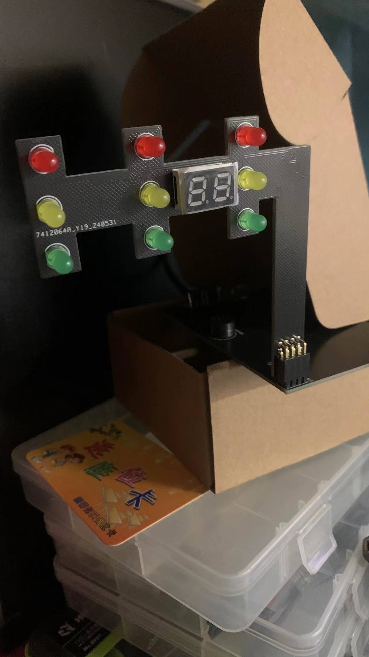 Figure 5: 3D rendering.
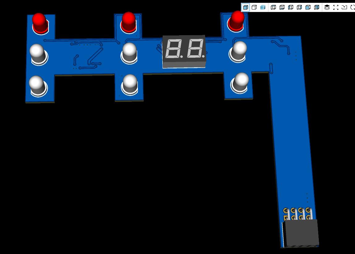
 Back view:
  Notes:
 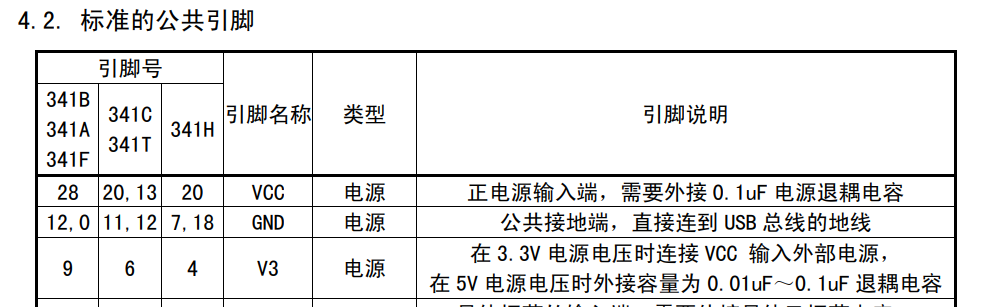 The project includes two projects, "No Level Conversion" and "Level Conversion." In the "No Level Conversion" project, pin 9 is connected to VCC, but when programming 5V chips, VCC will have a 5V voltage, which does not conform to the manual specification. This has no impact in actual use (long-term stability is unknown). It is recommended to modify it yourself or use the "Level Conversion" project.
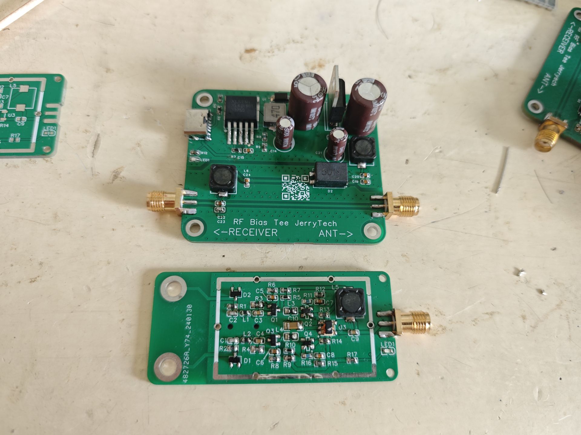


 京公网安备 11010802033920号

 ICS8304


