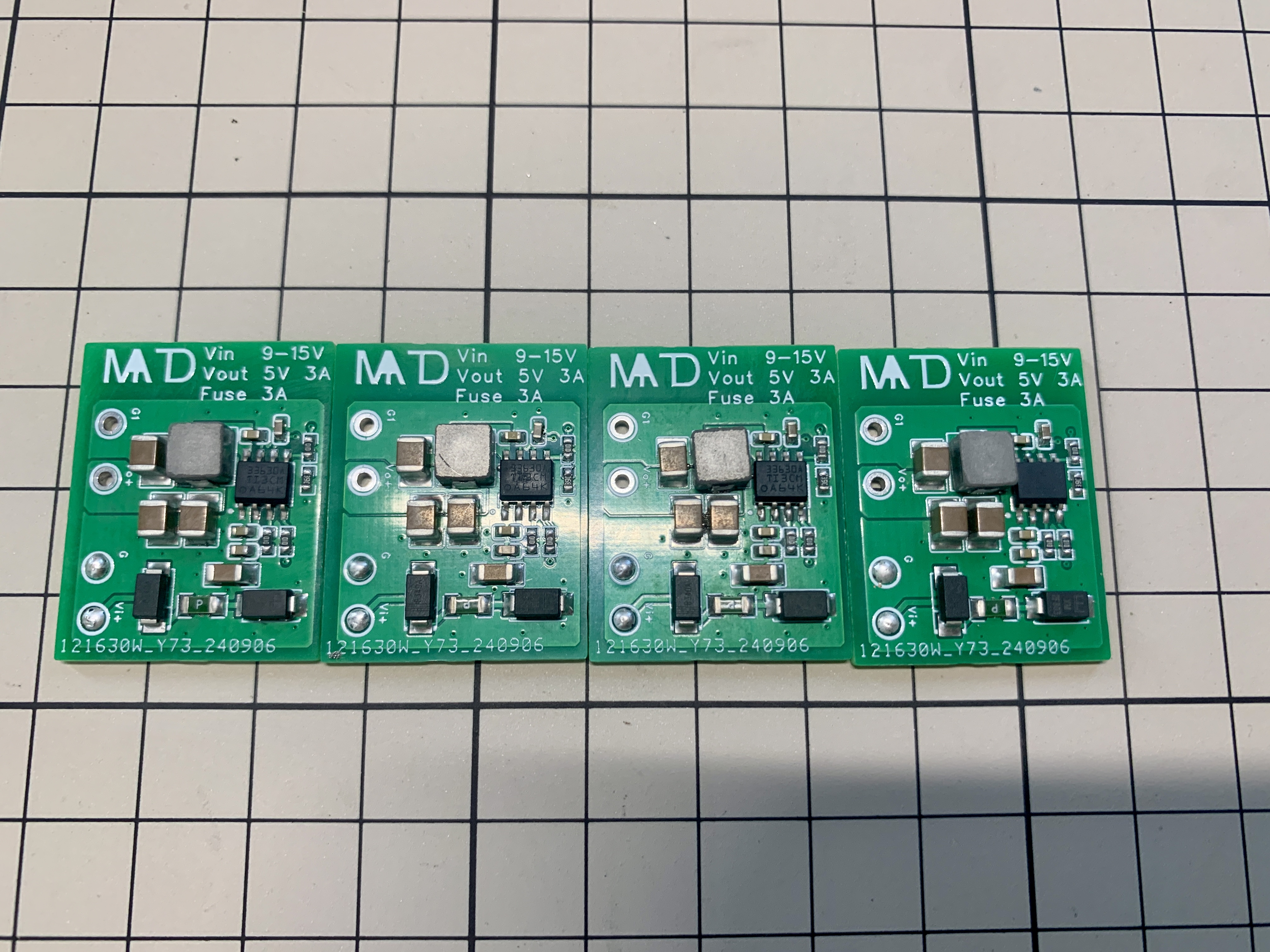
//Because V1.1 and V1.2 used an LDO to convert 24V to 5V, the voltage difference was too large, resulting in severe heat generation. Therefore, V1.3 was changed to a DC-DC converter to 5V, effectively reducing voltage and heat generation, but this may introduce some power supply interference. The choice of version can be considered accordingly; V1.3 is recommended.
In addition, the board also has reserved solder points for selecting the switching frequency. Regarding frequency selection: (Short-circuit solder point selection; soldering as shown in the diagram indicates the lowest frequency. A more appropriate frequency can be selected, but increasing the frequency will cause even more heat generation.)
BOM_Small Round Screen Amplifier Board - V1.2 Buying Guide and Price Reference Table.xlsx
Function Description:
DIY 5G CPE Adapter Board/5G Module to USB Adapter Board.
Tested download speed: 300Mbps+.

Open Source License:
CC BY-NC-SA 4.0.
Notes:
The Type-C interface only supports USB 3.0 on one side. Different LED colors indicate the orientation: pinkish-purple for USB 3.0, yellow for USB 2.0
. The antenna spacing is too small; please select an antenna with a diameter <12mm or use an antenna extension cable (antenna panel hole spacing adjusted to 14mm).
The heat dissipation space is approximately 10.6mm high, 48mm wide, and 60mm long. The heatsink and fan must
be smaller than these dimensions. Issues:
I've been busy lately and won't be making further modifications for now. Welcome to continue sharing a more perfect version.
The inductor makes a whistling sound under high load; this may be due to an unreasonable inductor/power supply design. The order was placed hastily;
a MUX chip needs to be added.
The LED placement is slightly inward, supporting reversible Type-C interface , and requires
further adjustment.
This project has been verified, but the following modifications were made after verification:
antenna spacing was increased, the position of some panel interfaces was slightly adjusted
, the outer contour of the adapter board was adjusted and copper plating
was reapplied, and the soldering stud pad connection method was changed to divergent for easier soldering.
Acknowledgements:
This project is based on @炽羽渡尘's project with slight modifications. The positions of the SIM female connector and power supply were adjusted to fit the housing.
References:
https://blog.siriling.com:1212/2023/04/12/5g-modem-fibocom-fm350-gl/
https://blog.csdn.net/qq_41354243/article/details/140923865
https://oshwhub.com/yizhidianzi/gl3224-usb3-0-sdio
https://www.waveshare.net/wiki/RM500U-CNV
The Texas Instruments eZ-FET-Lite debugger, based on the MSP430F5528, uses a circuit derived from the publicly available schematic of the 5529LP. It can be used with UniFlash or CCS to develop or program Texas Instruments' MSP430F55 series microcontrollers.
Introduction:
eZ-FET-Lite, launched by Texas Instruments (TI), is a lightweight debugger for onboard programmers and debuggers on MSP430F5529 and other series of microcontroller development boards. It uses the MSP430F55xx series microcontroller with USB peripherals as the main control chip, converting it into a serial port and TI's unique SBW interface (essentially a modified SWD) for microcontroller programming/debugging. Commonly found on early TI microcontroller development boards, it has now been replaced by the XDS110 series onboard debugger. Currently, its main purpose is to debug devices with older TI microcontrollers or to restore firmware for other eZ-FET-Lite devices (this is where TI's abstract approach comes in). The author's main purpose in creating this debugger was to try flashing the EV2400 firmware onto the F5528 using the eZ-FET-Lite after repeated unsuccessful attempts with the MSP430F5528.
Schematic & PCB Design:
The schematic for this eZ-FET-Lite is a modified version of the programmer section of the Texas Instruments MSP430F5529 LaunchPad, almost a complete copy. I added some ESD protection circuitry and a USB-BSL download circuit (a useful function that Texas Instruments didn't use, resulting in bricked eZ-FET-Lite units needing to be restored using another working eZ-FET-Lite, which is quite abstract). I replaced the power supply IC with an easily found one, added a reset button, and brought out the programming port. That's about it. A few points to note when replicating:
I recommend soldering the F5528 and USB connector first, then the rest, otherwise it's difficult to solder.
For the F5528, I suggest finding a used, cut-down board on Xianyu (a second-hand marketplace) and disassembling it yourself. Taobao has no good quality ones; I've bought seven and none have worked properly. Alternatively, if you have a broken 5529 development board, you can simply remove the 5528 from it, saving you the trouble of programming.
You or a classmate need to have an eZ-FET-Lite first, otherwise you can't program it (I know this sounds incredible, but I had no choice; this is how Texas Instruments made it, so this is the only way. I heard there was a BSL programming program for the 5528, but I haven't found it yet; I'm still exploring).
The attachment contains firmware extracted from a working eZ-FET-Lite. You can also download the publicly available eZ-FET-Lite resource package from Texas Instruments and find the firmware there.
Programming steps (also the method for unbricking an eZ-FET-Lite):
(Most of this text is copied from @hexesdesu, thank you!)
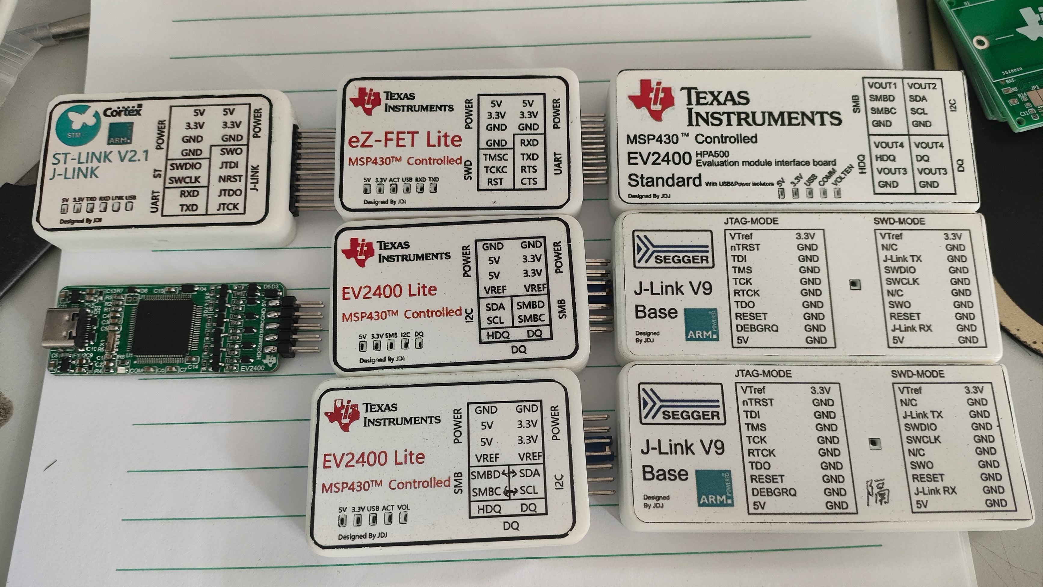
Find a programmer that can program the 5528. The LaunchPad's onboard eZ-FET-Lite or FET430UIF will work. Connect it to the prepared board in the following order: SBW-RST-->RST; SBW-TST-->TEST; 3V3-->3.3V; GND-->GND.
Install the UniFlash tool on your computer and download the Ez-FET lite resource package.
Unzip the resource package and find the firmware file eZ-FET lite rev 1.10 Release PackageFirmwareEZFET_LITE_Rev1_1_BSL_1_1.txt. Copy it out (you can also use the new firmware I uploaded below).
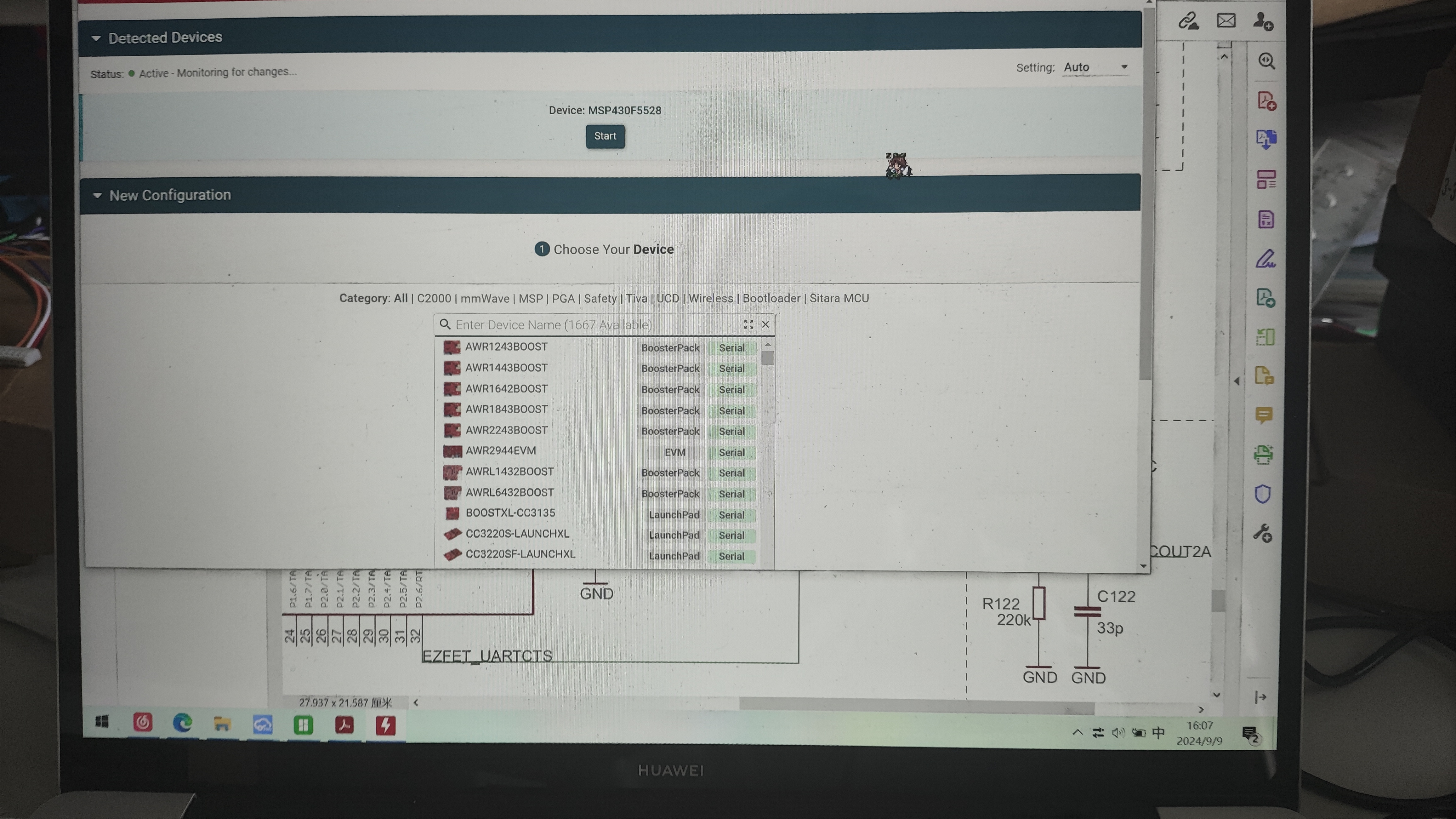
Open UniFlash, select the MSP430F5528 chip and connector. The first connector should be selected by default. (For the current version, there's an auto-detection option at the top. If auto-detection is enabled and the programmer is properly connected to the microcontroller, it will automatically recognize the target microcontroller. Just click on it (as shown in the image, simply click START to enter).)
On the Settings & Utilities page, find the Erase section and click Mass Erase. Wait for the erasure to complete. (Do not click EraseByAddress. If you are using the firmware with addresses 0x00-0x243ff or 0x4400-0x243ff below, you can enter those addresses in Start and EndAddress to perform a full chip erase.)
In the Download section above, check Allow Read/Write/Erase access to BSL memory. Return to the Program page
and select the firmware you just copied in Flash Image(s). (If you used the firmware I uploaded in the previous steps, select the corresponding firmware here.) Click Load. Upload the firmware to the image and wait for the upload success message.
Disconnect the burning cable and plug the target board directly into the computer. The computer will make a sound indicating a new device has been inserted, but you won't see it in Device Manager. Don't panic.
Open CCS or Energia (IAR hasn't been tested), and choose any program to upload. It will prompt you to update the firmware; select update (Energia will update automatically). After the update, your computer will see the two serial port devices. (If you use the new firmware extracted from the attachment below, this problem will not occur, and it will be recognized directly.)
Shell:
The shell is printed using a 3D printer. The attachment includes the files and sticker files. It is recommended to print the sticker files on 32x52mm A4 self-adhesive paper. The shell and sticker files are in the attachment. You will need to use M2 thermoplastic nuts and countersunk screws to connect the top and bottom covers.
Usage Example:
As I mentioned earlier, I made this for flashing firmware onto the 5528. Actually, it's not really a forced flash, because the MSP430F55 series uses the same core; only some peripherals differ. The EV2400 only uses a few pins. Those cheap domestic EV2400s on Taobao and Xianyu are actually from this source. Other ICs in the MSP430F55 series, flashed with EV2400 firmware, won't cause problems when operating non-existent peripherals, so they can still run normally. Since it's the same core, there's no question of one being better than the other; it's just that cheaper ones use salvaged parts with unknown remaining lifespans.
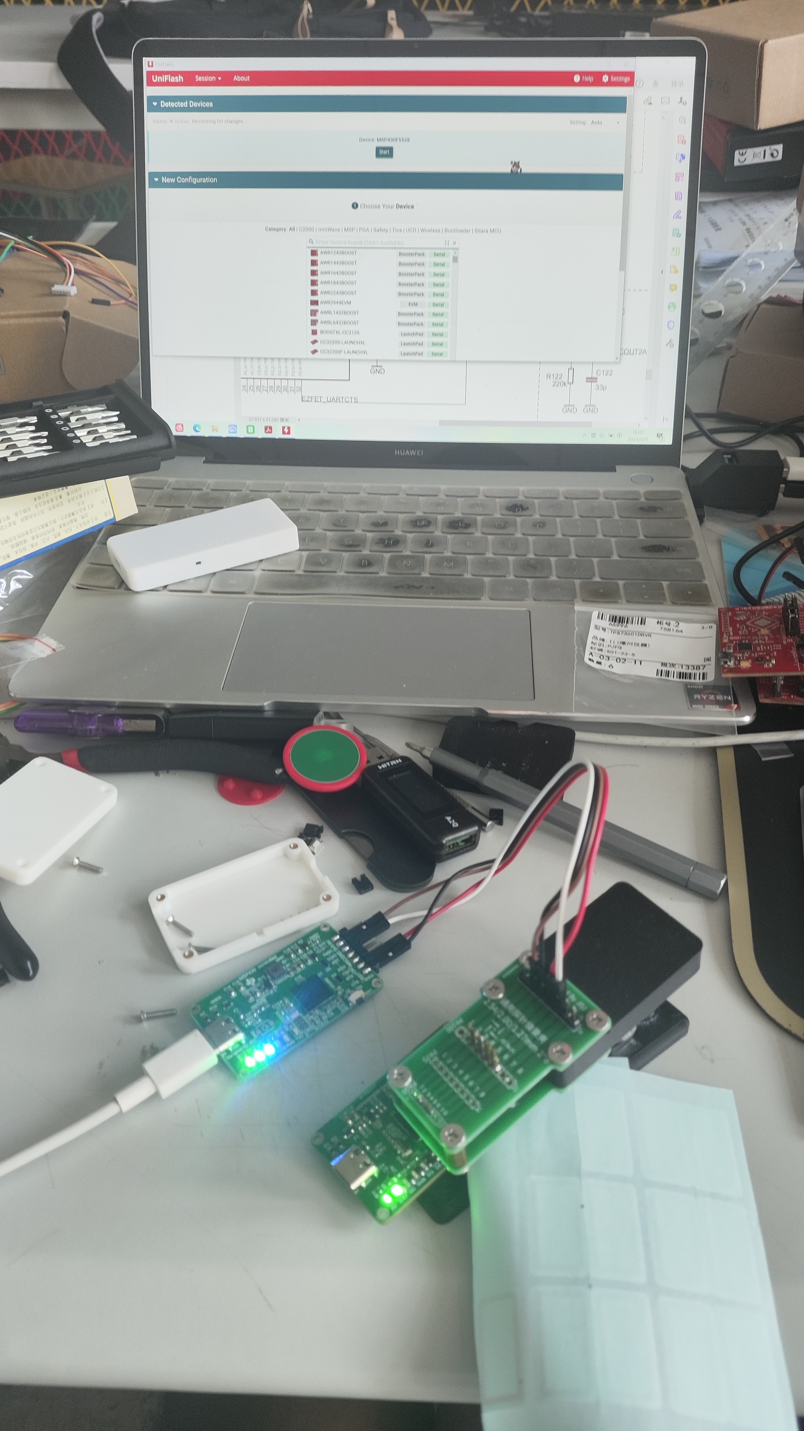
Attached are some usage photos without a case:
(Burning the EV2400's F5529 program onto a 5528 using the EV2400 after a failed USB-BSL flashing attempt).
Photos of it used with the flashing clip
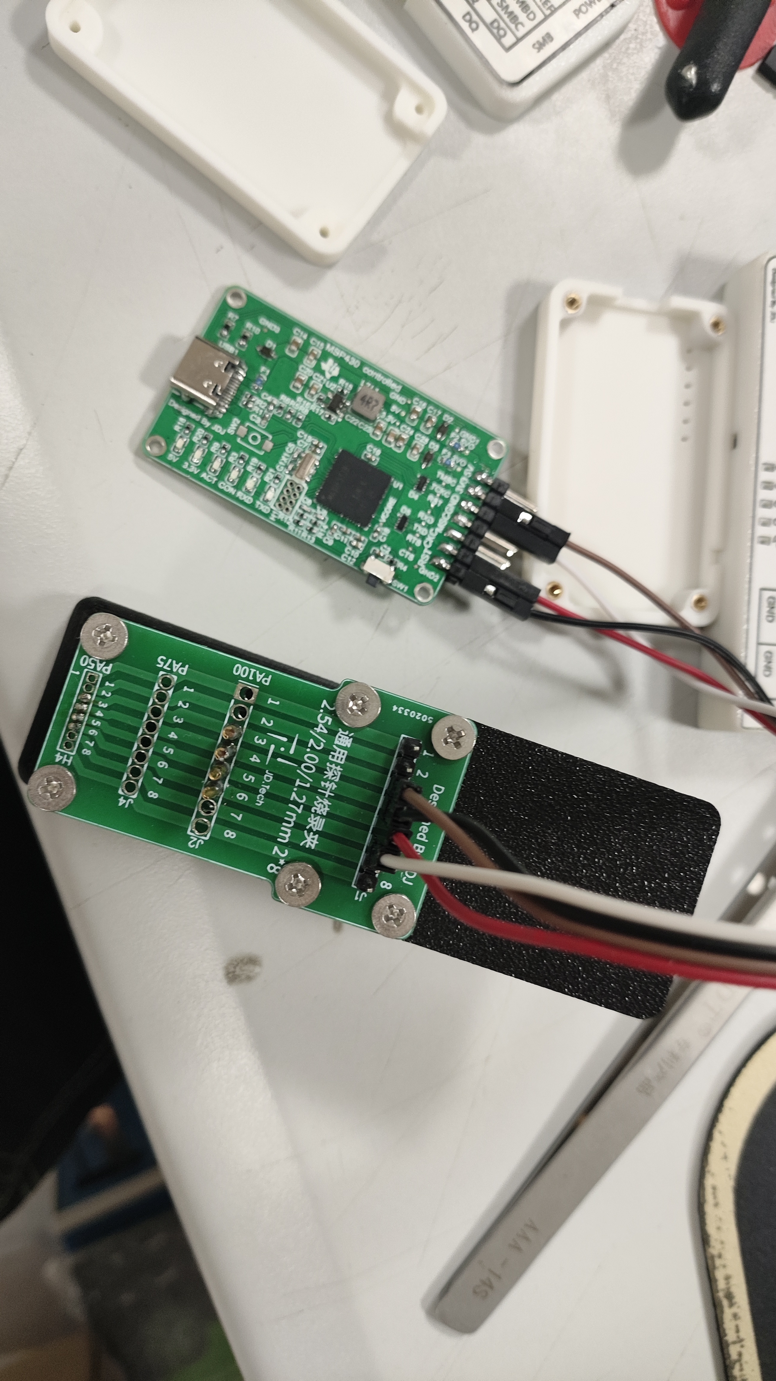
. A debugger that has been made and tested is also available (the standard EV2400 and 5528 versions of the EV2400 will be open-sourced later).
eZ-FET_lite_Release_Package_rev_1_10_20130712.zip
EZ-FET-0X00-0X243FF.bin
EZ-FET-REV1.8-FROM0X4400TO0X243FF.bin
eZ-FET-Lite.psd
eZ-FET-Lite.png
3D_eZ-FET top cover 2024-05-22 v1.3mf
3D_eZ-FET bottom cover 2024-05-22 v1.3mf
PDF_[Verified] eZ-FET-Lite Debugger-Programmer.zip
Altium_[Verified] eZ-FET-Lite Debugger_Programmer.zip
PADS_[Verified] eZ-FET-Lite Debugger_Programmer.zip
BOM_[Verified]eZ-FET-Lite Debugger_Programmer.xlsx
92167
A card dealing machine
DIY Card Dealer for 100 Yuan V1.2
Fast, lightweight, no-shuffle, and I believe it's better than those on the market. The hardware and software are almost complete; it's open source, so let's all play together.
The main controller is a 328P; pins and storage space are almost used up. If new features are needed, I'll consider porting them to an ESP32.
Related videos are on Bilibili. Files and BOM are being organized. Code and print files are at https://github.com/heute666/smart-poker-dealer.
Related videos on Bilibili: https://space.bilibili.com/554504409. For now,
the images look like V1.1. I initially wanted to put the touch chip on the motherboard, but it didn't work well, including the indicator lights. It has been updated to V1.2.
The attachments include STL files, BOM, and PCB layout files for the card-dispensing sensor (necessary); PCB layout files are also available in the repository (not necessary; a tracking sensor can be used instead, but other wiring needs to be done manually).
cardout_sensor.rar
card_carbin_pcb.zip
stl.rar
BOM_v2.xlsx
BOM_A Card Dealer.xlsx
POKERDEALER_MAIN.zip
POKERDEALER_TOUCHPANEL.zip
PDF_A Card Dealer.zip
Altium_A Card Dealer.zip
PADS_A Card Dealer.zip
92170
STM32F407VET/VGT Universal Car Expansion Board
This expansion board, based on JLCPCB's SkyStar Youth Edition STM32F407VET6/VGT6, has 80 pins brought out, supporting screen display, four motors driven by two TB6612 chips, eight grayscale sensor ports, a wireless serial port, and Bluetooth communication.
This expansion board can be used with STM32F407Vet6 or VGT6 for learning and building car projects. Besides the external modules, you need to provide your own, including switches, headers, pin headers, etc. The cost of replicating this
board is less than ten yuan. The interfaces supported by the board are as follows: if you need to know the corresponding pins, you can open the schematic diagram of the project and match them one by one.
1. Step-down module


2. TB6612 motor drive module

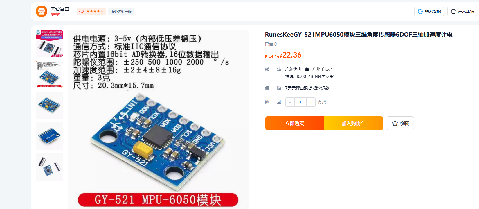
3. MPU6050 6-axis module
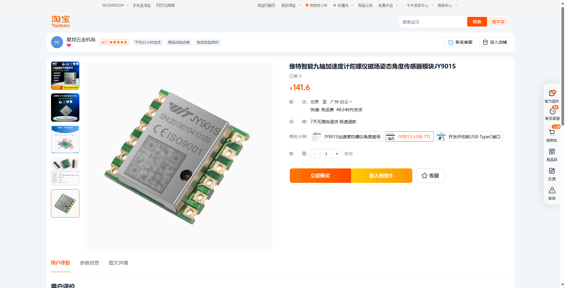
4. Witt gyroscope – reserved serial communication interface
5. Eight-channel grayscale tracking sensor interface – any tracking sensor on the market can be used (the one used here is from Senvi).

6. 0.96-inch OLED screen interface, using I2C communication, replaceable color screen, any I2C-compatible screen is compatible.

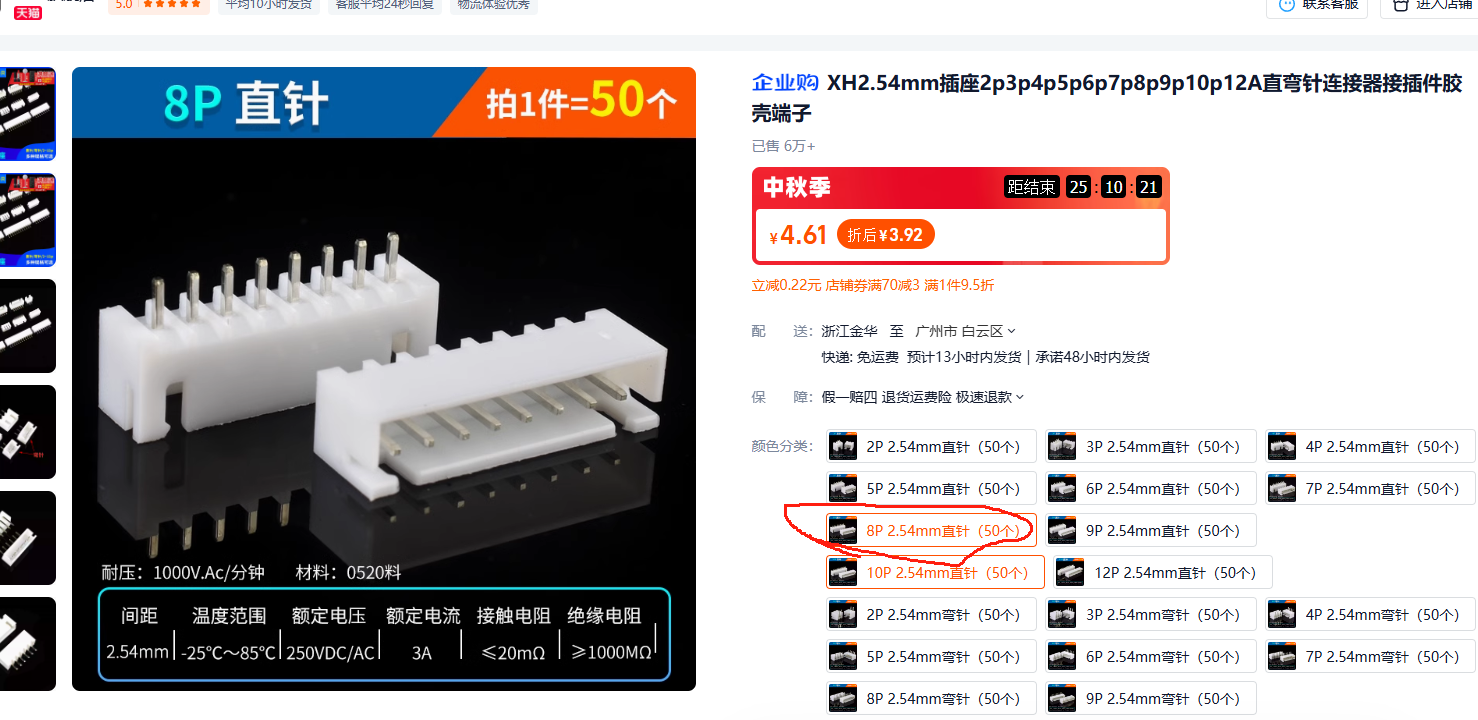
7. Four motor XH-2.54-8P interfaces, all with encoder acquisition support interfaces, pre-assigned.
8. SR-04 ultrasonic interface (supports tracking and obstacle avoidance, etc.).

9. Bluetooth module interface - 4P.

Replica expansion board supported modules.pdf
PDF_STM32F407VET-VGT Universal Car Expansion Board.zip
Altium_STM32F407VET_VGT Universal Car Expansion Board.zip
PADS_STM32F407VET_VGT Universal Car Expansion Board.zip
BOM_STM32F407VET_VGT Universal Car Expansion Board.xlsx
92171
Logitech G102 Mouse Adapter Board 5+1 Buttons
Simple and practical scroll wheel included
Project Origin:
This project originated from a sudden inspiration during my daily gaming.
Some game scenarios require relatively complex operations, such as repetitive buying and selling, etc.
The usage frequency is not high, but it is very tedious. It is not cost-effective to use a mouse and customize the button. Therefore, this project was created.
Functionality:
It uses Logitech's official control software to customize its functions and realize one-click macro operation.
Principle Analysis (Hardware Description):
Directly bring out the button. The difficulty is relatively low.
Precautions:
Bring out the onboard button. The button has a common ground. The encoder is the second generation. Early and first generation have 1K resistors and capacitors. Be careful not to damage them during soldering. It can also be directly integrated into the adapter board. Be careful not to leave too short the flying wire.
Assembly Process:
After the flying wire is completed, use copper pillars to clamp the motherboard in the middle of the adapter board. Actual
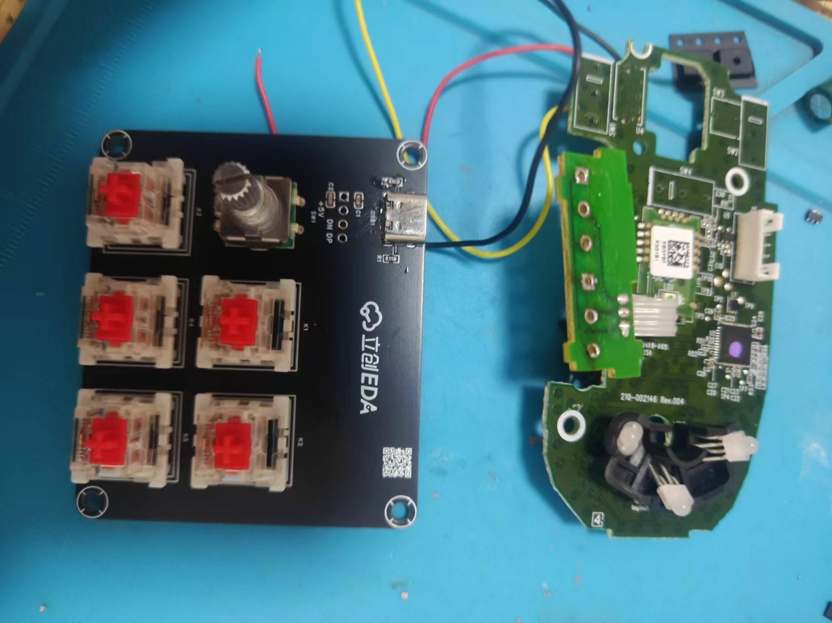

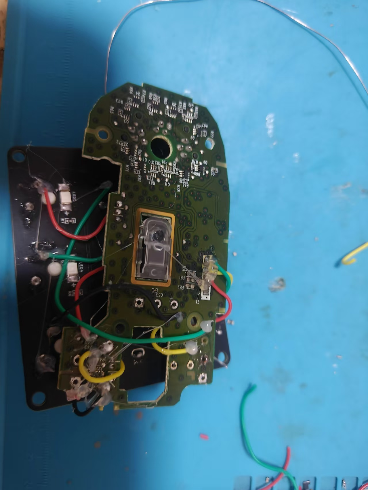
Product Image

Replica Cost:
The material cost is no more than 10 yuan. The switch is TB. The trial pack of Gateron is 4 yuan for 10.
The encoder is just a regular EC11 for about 2 yuan.
The G102 main control board is about 20 yuan on Xianyu. Motherboards with double-click are also available because the double-click fault is due to the microswitch.
The
adapter board cannot completely cover the motherboard. You can cut the board and fly the wire.
The USB ports are not sufficient. The future will integrate HUB function. Please look forward to it.
PDF_Logitech G102 Mouse Adapter Board 5+1 Buttons.zip
Altium Logitech G102 Mouse Adapter Board (5+1 Buttons).zip
PADS Logitech G102 Mouse Adapter Board (5+1 Buttons).zip
BOM_Logitech G102 Mouse Adapter Board 5+1 Buttons.xlsx
92172
electronic

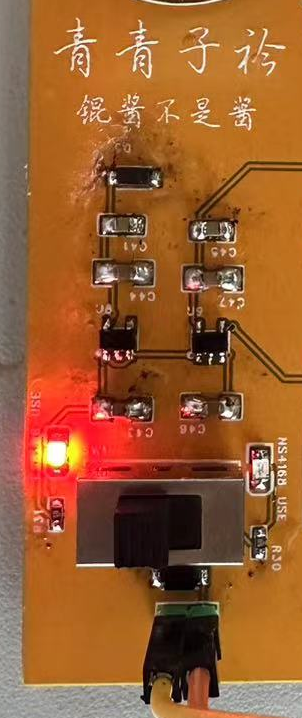
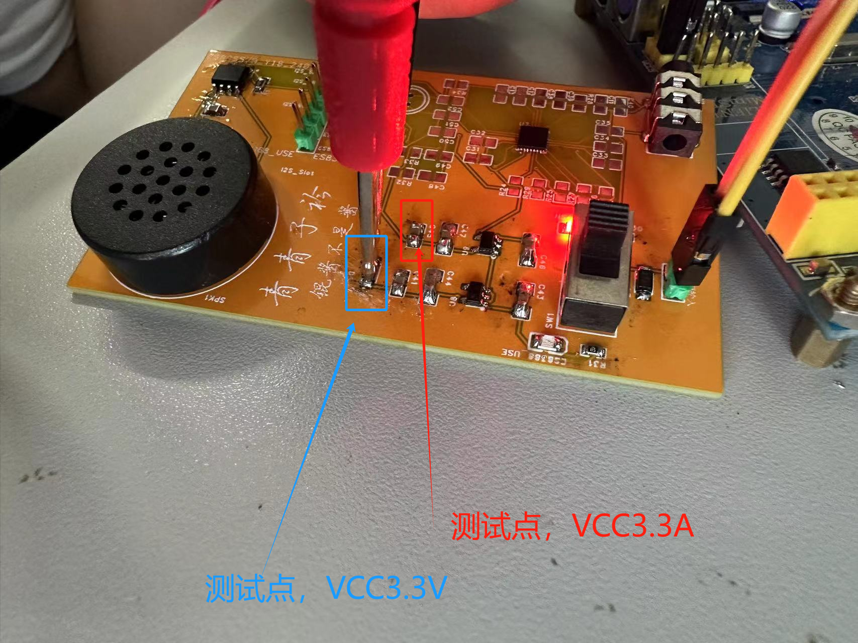
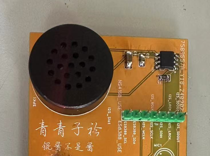
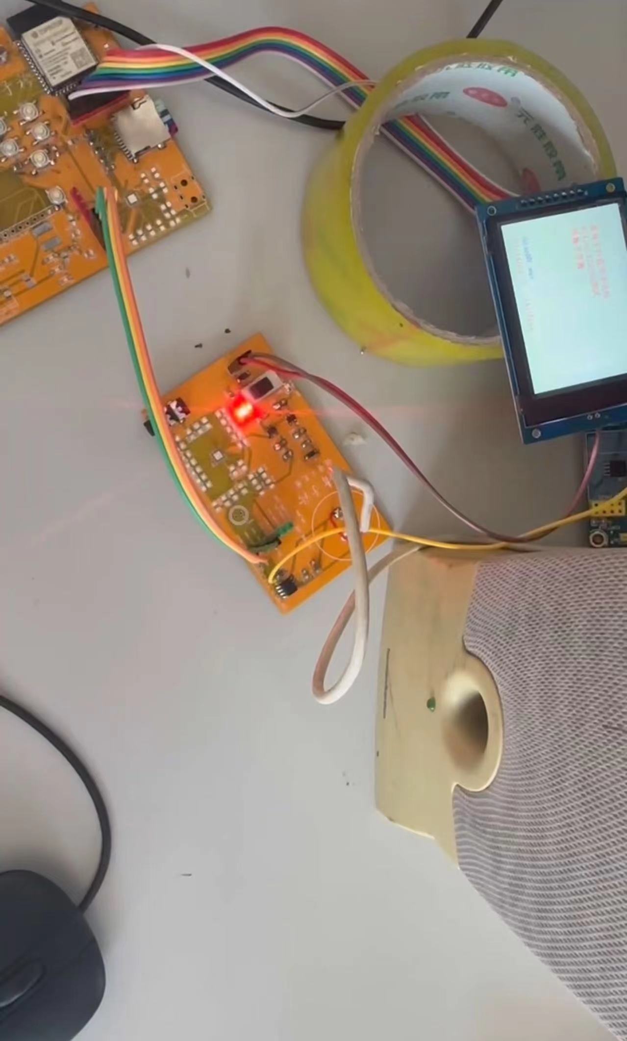
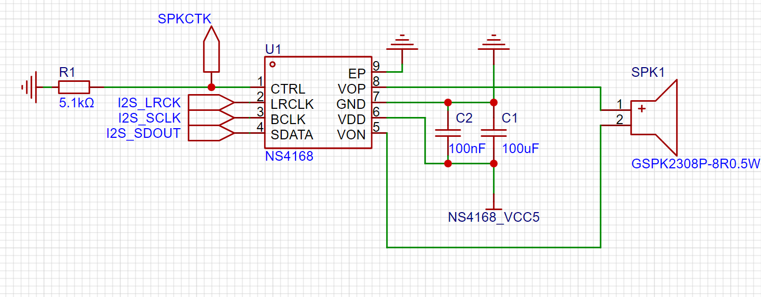 With a 5V power supply, the output power can reach 2.5W, making it a good choice for building small speakers. I placed an NS4168 chip on this evaluation board for testing purposes. Audio is output through the onboard speaker.
 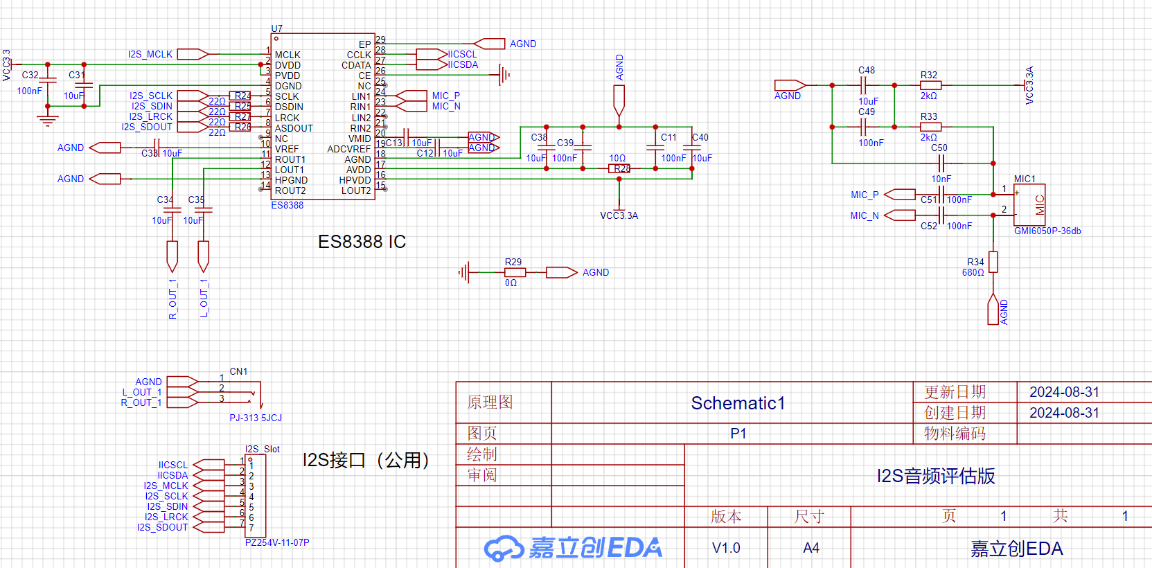 . This chip not only supports audio output but also audio input, offering dual-channel input and output


 6.8K 9V 24K 12V 56K 15VNC 20V,
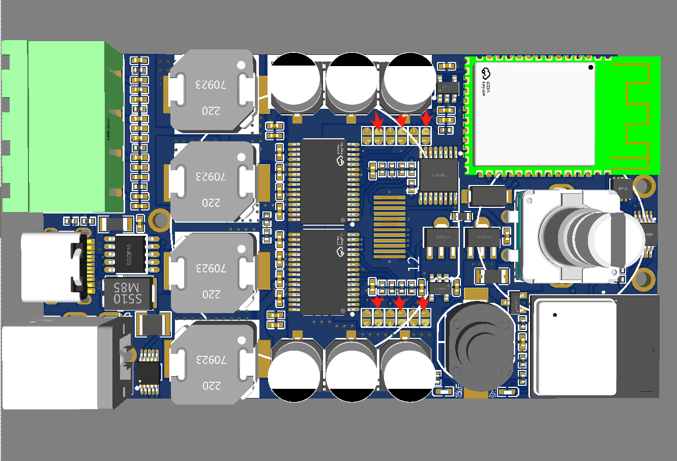


 京公网安备 11010802033920号

 MF-RX012/250U-A5-0


