This file contains the official open-source PCB for the OpenMV4 R1 board. It can be used for replacing damaged pins and for replicating designs. Please do not use it for commercial purposes.
CC meter, without deception, displays voltage, current and power.
This document describes
the use of an LDO to power a microcontroller
, an INA226 as the voltage and current acquisition chip,
and an OLED screen for display.

Issues and subsequent optimizations
: 1. Using an LDO for power supply can easily cause system restarts when the USB-B voltage changes; a DC-DC converter is planned for the next version.
2. There was a bug in the OLED screen circuitry (now fixed).
3. A resistor divider network using the CW32's built-in ADC has been added for functional verification.
4. The overall current flowing through the board is relatively low; the power supply issue for the Type-C port still needs to be addressed.
5. Reserved buttons have been removed.
I. Hardware Design
1. Power Supply Circuit
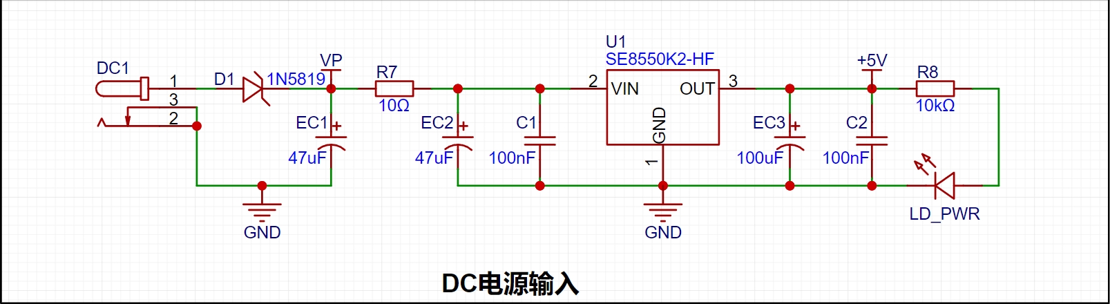
LDO (Low Dropout Linear Regulator) Selection This project uses an LDO as the power supply. Considering that most voltmeter products are used in industrial scenarios with 24V or 36V power supplies, the SE8550K2 with a maximum input voltage of up to 40V was selected as the power supply. The main reason for not using a DC-DC step-down circuit to handle the large voltage drop is to avoid introducing DC-DC ripple interference during the design process, and the secondary reason is to reduce project costs.
2. MCU Selection Analysis
To reduce the learning cost for everyone, this project uses the LCSC CW32F030C8Tx development board (core board) as the main controller, but this does not mean that we will talk less about this section. From the perspective of training engineers, the correct selection of the main controller is very important, as it relates to the overall advantage of the project. Regarding the voltmeter and current meter, the author used STM32/CW32 and some other 32-bit microcontrollers for some debugging and testing. This comparison is only with the STM32F103C8T6 as a reference for device selection, primarily aimed at providing ideas and improving understanding.
Avoid blind selection. When selecting an MCU (Microcontroller Unit) for this project, multiple aspects need to be considered to ensure the chosen MCU meets project requirements.
Clearly define your project needs: Understand the required computing power, including clock speed, processor core type, and whether a floating-point unit is needed.
Identify the required I/O ports and important peripherals, such as ADC peripherals. Since this is a development board project, primarily for debugging and learning, there are no strict limitations on the number of I/O ports: i.e., the associated costs are not considered.
Key advantages of the CW32 in this project
: Wide operating temperature range: -40~105℃;
Wide operating voltage range: 1.65V~5.5V (STM32 only supports 3.3V systems)
; Superior interference immunity: HBM ESD 8KV; All ESD reliability meets the highest international standard (STM32 ESD 2KV)
; Project focus - Better ADC: 12-bit high-speed ADC, achieving ±1.0LSB INL 11.3ENOB; Multiple Vref reference voltages... (STM32 only supports VDD=Vref);
Stable and reliable eFLASH technology.
A detailed explanation of these advantages will be provided in the chapters on ADC sampling and related extensions.
The main characteristics of the CW32 ADC: This project requires a focus on the 4 reference voltage sources. (Content from the "CW32x030 User Manual")
3. Voltage Sampling Circuit:
The voltage divider resistors in this project are designed to be 220K+10K, therefore the voltage division ratio is 22:1 (ADC_IN11).
The voltage divider resistor selection
is designed to measure the maximum voltage. For safety reasons, this project uses 30V (the actual maximum display value can be 99.9V or 100V).
The ADC reference voltage is 1.5V in this project, and this reference voltage can be configured through the program.
To reduce the power consumption of the sampling circuit, the low-side resistor (R7) is usually chosen as 10K based on experience.
Then, the high-side resistance of the voltage divider resistor can be calculated using the above parameters.
The required voltage division ratio is calculated, i.e., the ADC reference voltage. The input voltage is designed; using known parameters, 1.5V/30V = 0.05 can be calculated.
The high-side resistance is calculated as the low-side resistance/voltage division ratio; using known parameters, 10K/0.05 = 200K can be calculated.
A standard resistor is selected: a resistor slightly higher than the calculated value of 200K is chosen. We usually choose E24 series resistors; therefore, in this project, 220K, which is greater than 200K and closest to the calculated value, is selected.
If, in actual use, the voltage to be measured is lower than 2/3 of the module's design voltage (66V), the voltage divider resistor can be replaced and the program modified to improve measurement accuracy. The following example illustrates this:
Assuming the measured voltage is no higher than 24V and other parameters remain unchanged,
calculations show 1.5V/24V = 0.0625, 10K/0.0625 = 160K. 160K is a standard E24 resistor and can be directly selected, or a higher value 180K can be chosen with some redundancy.
If, in actual use, the voltage to be measured is higher than the module's 99V design voltage, a different resistor can be selected. To achieve a wider voltage measurement range, one can choose to replace the voltage divider resistor or modify the reference voltage. The following example illustrates this:
Assuming the measured voltage is 160V, the solution is to increase the voltage reference to expand the range.
Given that the voltage division ratio of the selected resistor is 0.0145, we can calculate 160V * 0.0145 = 2.32V using the formula. Therefore, we can choose a 2.5V voltage reference to expand the range (increasing the range will reduce accuracy).
Considering the potential fluctuations in the measured power supply, a 10nF filter capacitor is connected in parallel with the low-side voltage divider resistor to improve measurement stability.
Range switching:
In this project, an additional voltage sampling circuit was added. Therefore, we can discuss the significance of range switching for improving measurement accuracy. Multimeters often have multiple range settings for more accurate measurements. By adjusting different ranges, the optimal measurement accuracy of the measured point within the corresponding range can be obtained.
This project requires a combination of hardware and software to achieve this function. When we first use the ADC_IN11 channel mentioned earlier to measure voltages below 30V... If the measured voltage is within 0~3V, use the ADC_IN9 channel for measurement. In this case, the measurement accuracy is greatly improved due to the reduced voltage division ratio. There are many ways to implement gear shifting, and the development board design provides more design possibilities.
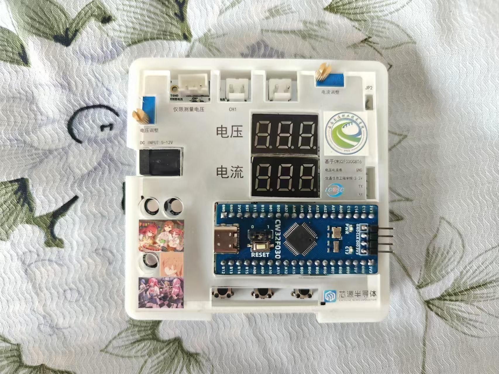
Physical diagram:
PDF_Voltmeter & Ammeter - Based on CW32F030C8T6.zip
Altium voltage and current meter - based on CW32F030C8T6.zip
PADS Voltage and Current Meter - Based on CW32F030C8T6.zip
BOM_Voltage and Current Meter - Based on CW32F030C8T6.xlsx
92931
electronic


 京公网安备 11010802033920号

 IDT70V27S35BF


