Video Link:
Bilibili Video -- Function Demonstration and Introduction
Project Overview
This project aims to develop a multi-functional desktop assistant integrating ChatGPT voice assistant, Bluetooth keyboard function, application quick launch, computer performance monitoring, weather and time information display, and music playback. It utilizes the ESP32 microcontroller as the core control unit, combined with various sensors and peripheral devices, to provide users with a convenient and intelligent desktop interaction experience.
Project Functions
1. ChatGPT Voice Assistant
Design a voice recognition algorithm to convert user speech into text commands. Through the ESP32's Wi-Fi function, text commands are sent to the ChatGPT server to obtain the response result. The response result is converted into voice output or displayed to the user on the screen.
2. Bluetooth Keyboard Function
Write a Bluetooth pairing and connection program to enable the desktop assistant to establish a Bluetooth connection with the computer. Design keyboard mapping logic to convert the desktop assistant's key operations into keyboard input that the computer can recognize. Support custom shortcut keys to achieve functions such as application quick launch.
3. Application Quick Launch
Write an application management program to identify and manage commonly used applications on the computer. Design a user interface to allow users to quickly launch or switch applications through the desktop assistant.
4. Computer Performance Monitoring:
Communicates with the computer via USB interface to obtain system performance data such as CPU, memory, and disk. Displays the performance data in real time on the screen, providing an intuitive performance monitoring interface.
5. Weather and Time Information Display:
Integrates a weather forecast API to periodically obtain and display current and future weather information. Designs a clock display interface to update and display the current time in real time.
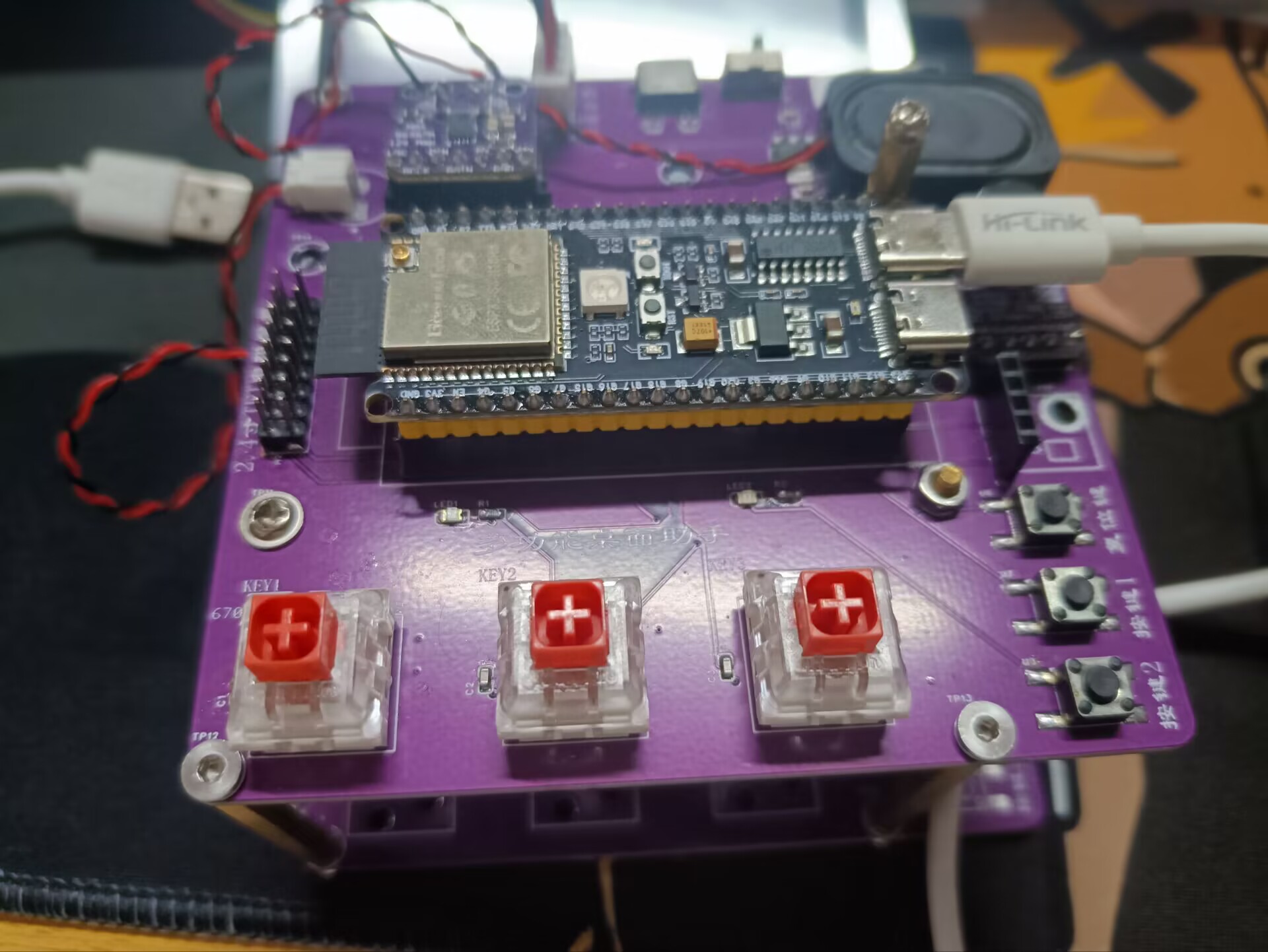
Project Parameters
: Uses ESP32S3 as the main controller.
MAX9814 for voice input,
MAX98357 I2S for voice output, and
GY-SHT30-D for temperature and humidity detection.
Principle Analysis (Hardware Description)
: First Version: Uses a Taojingchi serial capacitive touchscreen. It felt very sensitive. Later, it was found that too much UI was added, and the screen's built-in memory could no longer store it. This prevented many desired features from being implemented, forcing abandonment.
Second Version: Uses a 2.8-inch resistive touchscreen. After completing the UI, the resistive touchscreen felt very laggy... still not achieving the desired effect.
Third Version: Uses a 2.8-inch capacitive touchscreen.
The software code
was developed using VS Code, Platform.io, LVGL, Squareline Studio, and UART HIM.
1. GPT question answering is implemented using Doubao (a type of API) from the Volcano model.
#include
String apiUrl = "https://ark.cn-beijing.volces.com/api/v3/chat/completions";
const char *doubao_apiKey = "c0c9a9df-c65b-4e8f-a5dd-65e4c501ea49";
String getGPTAnswer(String inputText)
{
HTTPClient http;
http.setTimeout(20000);
http.begin(apiUrl);
http.addHeader("Content-Type", "application/json");
String token_key = "Bearer " + String(doubao_apiKey);
http.addHeader("Authorization", token_key);
String payload = "{"model":"ep-20240901212403-z677d","messages":[{"role":"system","content":"You are my AI assistant vor, you must answer in Chinese and the number of characters cannot exceed 85"},{"role":"user","content":"" + inputText + ""}],"temperature": 0.3}";
int httpResponseCode = http.POST(payload);
if (httpResponseCode != 200)
{
Serial0.println("HTTP Request Failed");
http.end();
return "";
}
String reason = http.getString();
http.end();
DynamicJsonDocument jsonDoc1(1024);
deserializeJson(jsonDoc1, reason);
return jsonDoc1["choices"][0]["message"]["content"];
}
2. Implement voice broadcasting through MinMax.
#include
const char *url = "https://api.minimax.chat/v1/t2a_pro?GroupId=1828638795172417679";
const char *apiKey = "eyJhbGciOiJSUzI1NiIsInR5cCI6IkpXVCJ9.eyJHcm91cE5hbWUiOiLlrabnlJ8iLCJVc2VyTmFtZSI6Iu WtpueUnyIsIkFjY291bnQiOiIiLCJTdWJqZWN0SUQiOiIxODI4NjM4Nzk1MTgwODA2Mjg3IiwiUGhvbmUiOi IxOTE4ODM3MzYwMyIsIkdyb3VwSUQiOiIxODI4NjM4Nzk1MTcyNDE3Njc5IiwiUGFnZU5hbWUiOiIiLCJNYW lsIjoiIiwiQ3JlYXRlVGltZSI6IjIwMjQtMDktMDMgMTc6MDg6MjAiLCJpc3MiOiJtaW5pbWF4In0.SnCyHWc tvTXvFISy04BvT1-EYqflqaeXuF1reK-U0ZMpomQ6Nc4F_KwsbgXDtvxx3rQWlGGeC_V4ykp-kr9oYLhX5bl MuRRxYIaR0G_UxJ0ftC1bEAimX4-niwp9BmsfNeBNbCPf13NOcOt_Mm7mLBDPbva7wXhK4Fw74yII_3mmpkV YM2M_aO0uVdEBhDn75MxkjonTK3tHiN3UIaDZoW0x87ASSZcDeX2zkruTmjmXPItXFSGzBHJFLN7zJbu2PAvt4PUC1IGtxqfkijVu8-CyG-iuH3yLES3ayPjcZoSCVXmrYtSFiZKhQWRjvY3QWD31NCQZkdtfY0dO2jnX1Q"; // Replace with your actual API key
/**
* @brief Get TTS Answer
*
* Sends an HTTP POST request to the specified URL to retrieve the TTS answer using the given input text.
*
* @param inputText Input text
*
* @return Returns the audio file link for the TTS answer
*/
String getTTSAnswer(String inputText)
{
HTTPClient http1;
http1.setTimeout(10000);
http1.begin(url);
http1.addHeader("Content-Type", "application/json");
String token_key = "Bearer " + String(apiKey);
http1.addHeader("Authorization", token_key);
StaticJsonDocument<1000> doc;
doc["text"] = inputText;
doc["model"] = "speech-01";
doc["audio_sample_rate"] = 32000;
doc["bitrate"] = 128000;
doc["voice_id"] = "presenter_male";
String jsonString;
serializeJson(doc, jsonString);
int httpResponseCode1 = http1.POST(jsonString);
if (httpResponseCode1 != 200)
{
Serial0.println("HTTP Request Failed");
http1.end();
return "";
}
String reason = http1.getString();
http1.end();
DynamicJsonDocument jsonDoc1(1024);
deserializeJson(jsonDoc1, reason);
return jsonDoc1["audio_file"];
}
3. Implement speech-to-text conversion using Baidu Smart Cloud.
HTTPClient http_client;
uint16_t adc_data[data_len];
uint8_t adc_start_flag = 0;
uint8_t adc_complete_flag = 0;
char data_json[45000];
String response, question,answer;
DynamicJsonDocument jsonDoc(1024);
uint32_t num = 0;
portMUX_TYPE timerMux = portMUX_INITIALIZER_UNLOCKED;
hw_timer_t *timer = NULL;
void IRAM_ATTR onTimer()
{
portENTER_CRITICAL_ISR(&timerMux);
if (adc_start_flag == 1)
{
adc_data[num] = analogRead(ADC);
num++;
if (num >= data_len)
{
adc_complete_flag = 1;
adc_start_flag = 0;
num = 0;
}
}
portEXIT_CRITICAL_ISR(&timerMux);
}
void setupRecorder()
{
pinMode(ADC, ANALOG);
pinMode(key, INPUT_PULLUP);
timer = timerBegin(0, 80, true);
timerAlarmWrite(timer, 125, true);
timerAttachInterrupt(timer, &onTimer, true);
timerAlarmEnable(timer);
timerStop(timer);
}
void handleRecognition()
{
if (digitalRead(key) == 0)
{
Serial0.printf("Start recognition
");
adc_start_flag = 1;
timerStart(timer);
while (!adc_complete_flag)
{
ets_delay_us(10);
}
timerStop(timer);
adc_complete_flag = 0; // Clear flag
memset(data_json, '', strlen(data_json)); // Clear the array:
`strcat(data_json, "{");
strcat(data_json, ""format":"pcm",");
strcat(data_json, ""rate":8000,"); // Sampling rate. If the sampling rate changes, remember to modify this value. There are only two fixed sampling rates: 16000 and 8000.
`strcat(data_json, ""dev_pid":1537,"); // Mandarin Chinese.
`strcat(data_json, ""channel":1,"); // Mono.
`strcat(data_json, ""cuid":"666666","); // Identifier code. Enter any characters, but preferably unique. `
strcat(data_json, ""token":"24.6030159d191427253c659ecc913283ae.2592000.1728034958.282335-114728200","); // token` Here you need to modify it to your own obtained token.
`strcat(data_json, ""len":32000,");` // Data length. If the transmitted data length changes, remember to modify this value. This value is the number of bytes of data collected by the ADC, not the length after base64 encoding.
`strcat(data_json, ""speech":"");
` `strcat(data_json, base64::encode((uint8_t *)adc_data, sizeof(adc_data)).c_str());` // Base64 encoded data.
`strcat(data_json, """);
` `strcat(data_json, "}");
` `int httpCode;
` `http_client.setTimeout(5000);
` `http_client.begin("http://vop.baidu.com/server_api");` // https://vop.baidu.com/pro_api
`http_client.addHeader("Content-Type", "application/json"); ` `
httpCode = http_client.POST(data_json);`
`if (httpCode == 200)`
{
if (httpCode == HTTP_CODE_OK)
{
response = http_client.getString();
http_client.end();
deserializeJson(jsonDoc, response);
String question = jsonDoc["result"][0];
Serial0.println("
Input:" + question);
answer = getGPTAnswer(question);
Serial0.println("Answer: " + answer);
String len = getTTSAnswer(answer);
set_voice(len);
}
else
{
Serial0.printf("[HTTP] GET... failed, error: %s
", http_client.errorToString(httpCode).c_str());
}
}
Serial0.printf("Recognition complete
");
}
vTaskDelay(1);
}
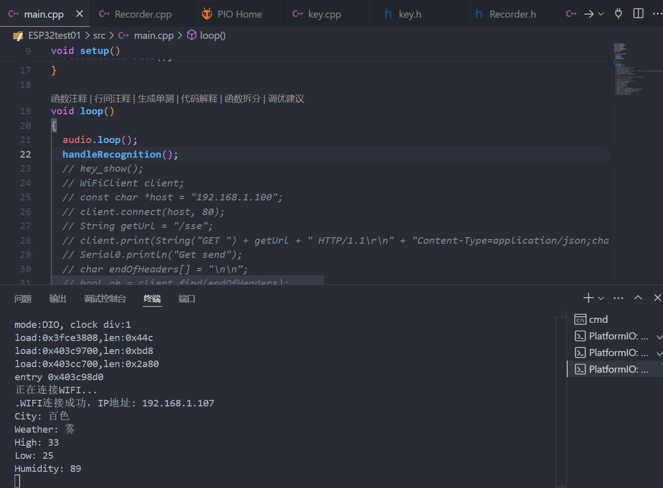
4、通过调用和风天气的API实现未来三天的天气监测。
const char *privateKey = "SWx9ptkZnxlmmy3V5";
const char *city = "百色";
const char *language = "zh-Hans";
HTTPClient client1;
void fetchWeatherData()
{
String getUrl = "/v3/weather/daily.json?key=" + String(privateKey) + "&location=" + String(city) + "&language=" + String(language);
client1.begin("http://api.seniverse.com" + getUrl);
int httpResponseCode = client1.GET();
if (httpResponseCode > 0)
{
String payload = client1.getString();
DynamicJsonDocument doc(1400);
deserializeJson(doc, payload);
WeatherData weatherdata;
strcpy(weatherdata.city, doc["results"][0]["location"]["name"].as());
strcpy(weatherdata.weather, doc["results"][0]["daily"][0]["text_day"].as());
strcpy(weatherdata.high, doc["results"][0]["daily"][0]["high"].as());
strcpy(weatherdata.low, doc["results"][0]["daily"][0]["low"].as());
strcpy(weatherdata.humi, doc["results"][0]["daily"][0]["humidity"].as());
Serial0.println("City: " + String(weatherdata.city));
Serial0.println("Weather: " + String(weatherdata.weather));
Serial0.println("High: " + String(weatherdata.high));
Serial0.println("Low: " + String(weatherdata.low));
Serial0.println("Humidity: " + String(weatherdata.humi));
}
else
{
Serial0.println("Error fetching weather data");
}
client1.end();
}
5、通过AIDA64来实现获取电脑的运行状态和时间。
client.print(String("GET ") + getUrl + " HTTP/1.1
" + "Content-Type=application/json;charset=utf-8
" + "Host: " + host + "
" + "User-Agent=ESP32
" + "Connection: close
");
Serial0.println("Get send");
char endOfHeaders[] = "
";
bool ok = client.find(endOfHeaders);
if (!ok)
{
Serial0.println("No response or invalid response!");
}
Serial0.println("Skip headers");
String line = "";
line += client.readStringUntil('
');
Serial0.println("Content:");
Serial0.println(line);
int16_t dataStart = 0;
int16_t dataEnd = 0;
int16_t cpu_frequence;
String dataStr;
char cpuFreq[] = "CPU fequence";
dataStart = line.indexOf(cpuFreq) + strlen(cpuFreq);
dataEnd = line.indexOf("MHz", dataStart);
dataStr = line.substring(dataStart, dataEnd);
cpu_frequence = dataStr.toInt();
Serial.print("CPU usage :");
Serial.println(cpu_frequence);
6. Display information through the Taojingchi serial port screen.
Precautions
1. Be sure to choose a good screen, otherwise the refresh rate will be too low. I suggest using an ISP capacitive touch screen or an 8080 parallel port screen.
2. Be sure to choose a suitable speaker, otherwise the sound will be very low.
3. Using AIDA64 to obtain the computer's running status is to set your computer's URL to a fixed value so you don't have to reset it every time.
4. Infinite rebooting when porting LVGL to ESP32. Increase the stack size of the ESP32.
5. When using LVGL for the UI, pay attention to file size; it's best to use an SD card.
6. Use the X series when using a Taojingchi serial port screen.
7. Pay attention to the steps when enabling Bluetooth and Wi-Fi simultaneously on the ESP32.
8. Provide a stable power supply to the circuit.
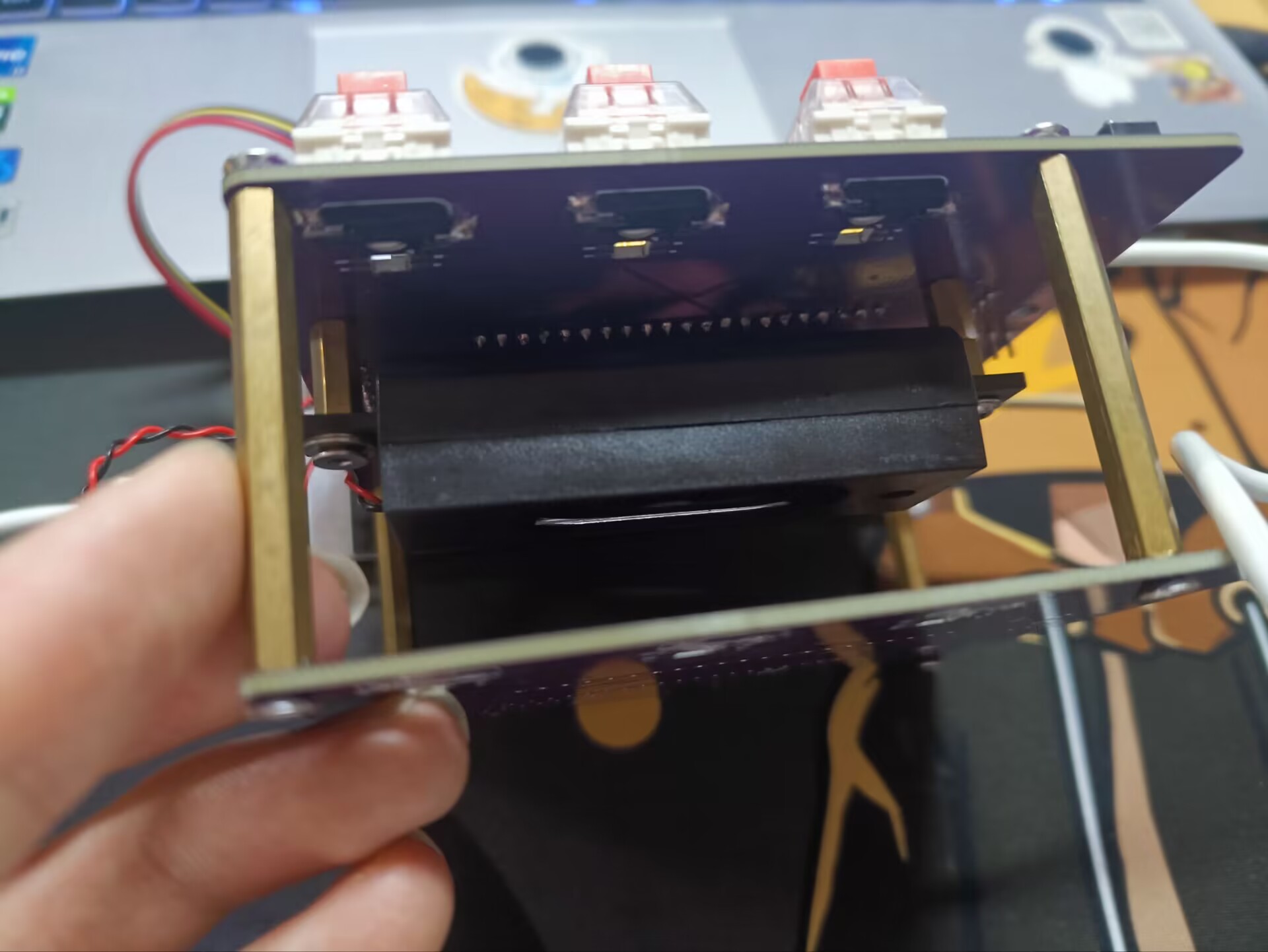
Assembly process photos
will be added later.


UI2.pptx
20240818_1.HMI
870e6e38cd1d3368df83d4c53b26c7d0.mp4
c4ed896d81deb3920c9bce94d069f447.mp4
ESP32test01.zip
PDF_ESP32-based Desktop Assistant.zip
Altium_ESP32-based desktop assistant.zip
PADS_ESP32-based Desktop Assistant.zip
BOM_ESP32-based Desktop Assistant.xlsx
92200
ESP32 Desktop Assistant
ESP32 Desktop Assistant
The ESP32 Desktop Assistant
uses the ESP32-S2 module as the main controller.
The programming mode is a serial port automatic switching programming circuit.
There are three buttons:
Button 1, manually turn the LED on/off
; Button 2, manually restart the MCU;
Button 3, pending.
After powering on, it connects via the ESP32-S2's Wi-Fi peripheral.
Once connected, it uses a WiFi Client to connect to the weather website host and sends a request to acquire weather data.
The weather data is parsed and displayed on a 2.4-inch TFT color screen.
The time is refreshed every 30 seconds, and the weather data is refreshed every 10 minutes.
Data exchange with the ESP32-S2 main controller can be achieved via a network on a mobile phone or computer, enabling control.
Physical demonstration link:
[ESP32 Desktop Assistant] This project is open source on the JLCPCB Open Source Hardware Platform_Bilibili_bilibili
PDF_ESP32 Desktop Assistant.zip
Altium_ESP32 Desktop Assistant.zip
PADS_ESP32 Desktop Assistant.zip
BOM_ESP32 Desktop Assistant.xlsx
92201
ESP32-PLC-MINI
Common industrial control PLCs and frequency converters are replicated based on ESP32 to achieve similar operations to PLCs.
P.S.: Due to limited programming resources and funding, the current version is not ideal. Future improvements will include
network connectivity to control relays and switches for each circuit, and the ability to perform various intelligent controls via external devices.
PDF_ESP32-PLC-MINI.zip
Altium_ESP32-PLC-MINI.zip
PADS_ESP32-PLC-MINI.zip
BOM_ESP32-PLC-MINI.xlsx
92203
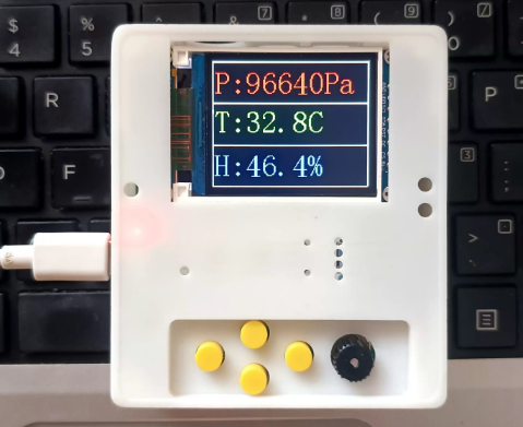
ESP32-based indoor monitoring tabletop
This design utilizes the ESP32-S3 development board to create an indoor monitoring desktop. Features include: 1- Support for monitoring indoor light, temperature, humidity, and pressure; 2- Support for wireless data transmission for convenient remote access; 3- Support for image playback; 4- Support for buzzer alerts; 5- Support for use as a desktop; 6- Support for battery charging and discharging.
Preface:
I've always wanted to learn ESP32, and this time I finally had the chance. I used to develop on Keil, but this time I followed LCSC's tutorials. Although the learning journey was bumpy, I've finally gained something. Anyway, even though I was late, I never missed a day.
I built it all myself, which is very rewarding.
Functional Design and Implementation Status:
1- Supports monitoring indoor light, temperature, humidity, and pressure data acquisition (completed).
2- Supports wireless data transmission for convenient remote access; AP + Bluetooth functionality has been verified and is awaiting integration.
3- Supports image playback; image display has been verified and is awaiting integration.
4- Supports buzzer alerts (completed)
. 5- Supports desktop placement (completed).
6- Supports battery charging and discharging (completed)
. 7- Supports low battery alarm (completed).
Hardware Design
: The main controller
uses an ESP32-S3, a development board purchased directly from LCSC. This project was also to learn ESP32; its 240MHz clock speed and dual-core support were the main reasons I was interested.
The pinout circuit of this board is as follows:

Button design:
To accommodate future functionalities, as many buttons as possible have been reserved.

A rotary encoder interface has also been reserved.

All the above circuits have added debounce capacitors; don't skimp on this!
Indicator light design:
Two pull-up indicator lights are reserved, plus one more indicator light on the development board. A total of three usable indicator lights. Display

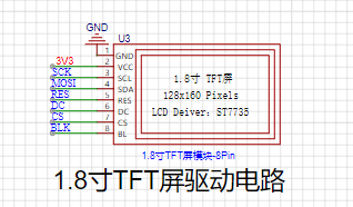
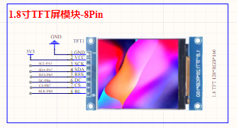
screen design:
I happened to have a 1.8-inch TFT display screen on hand, which I could utilize. I was learning how to drive a color SPI interface screen using an ESP32. This really stumped me. It was too difficult to adjust.
Charging and discharging circuit:
I purchased a TP5400 from LCSC; it's cheap and easy to use. I used this in almost all LCSC activities.
The circuit is simple, reliable, and practical. Just copy it directly.
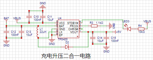
Lithium battery power monitoring:
A fully charged lithium battery is around 4.2V, requiring voltage division for data acquisition. It cannot exceed 3.3V, determined by the ESP32's AD converter. As shown below:

Light intensity detection
: A photoresistor is used; the stronger the light, the lower the resistance. Based on this principle, a pull-up voltage divider is used. The ESP32's AD converter then acquires the data. As shown below:

The buzzer
circuit has various alarms. The circuit is simple, as shown below:

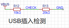
USB detection
can detect when the USB is plugged in for charging. Because the input is 5V, voltage division is performed to protect the interface.
As shown below: The temperature and humidity
sensor module
uses AHT21B to collect data, and the atmospheric pressure sensor uses BMP280.
Both use IIC interfaces, so the interfaces can share the IIC bus. As shown in the figure below:
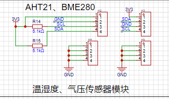
The tutorial does not include porting these two modules, as writing them yourself would be too painful. However, the lessons learned are also very rich.
The lithium battery interface
has a reserved 2.54mm pin header, which can be soldered or directly inserted.

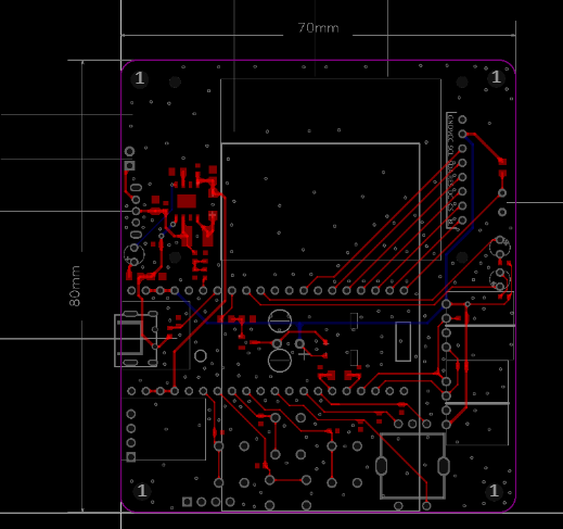
The PCB design
uses a 2-layer board, FR-4 board material, 1.2mm thick, and 70x80mm dimensions.
The casing design
uses LCSC EDA, and LCSC's 3D models are becoming increasingly realistic. The progress is really fast! Domestic EDA has a bright future.

The software design and development
follows the methods in the LCSC tutorial, and vscode and esp-idf are installed.
Here, I would like to remind everyone to use the version in the tutorial, otherwise, various problems will arise, and you will have to redo it.
Anyway, I went through all sorts of pain. Since this is a learning process, don't waste time on setting up the environment.
Later, I'll explain some areas where I spent a lot of time, especially where LCSC didn't provide direct examples. For
the screen driver,
I followed LCSC's tutorial, porting the framework from the 1.69-inch color screen to the 1.8-inch color screen.
First, the pin configuration:
#ifndef __LCD_INIT_H
#define __LCD_INIT_H
#include "driver/gpio.h"
#include "driver/spi_master.h"
#include "freertos/FreeRTOS.h"
#include "freertos/task.h"
#include "esp_rom_sys.h"
#define USE_HORIZONTAL 2 //Set landscape or portrait display 0 or 1 for portrait 2 or 3 for landscape
#if USE_HORIZONTAL==0||USE_HORIZONTAL==1
#define LCD_W 128
#define LCD_H 160
#else
#define LCD_W 160
#define LCD_H 128
#endif
#ifndef u8
#define u8 uint8_t
#endif
#ifndef u16
#define u16 uint16_t
#endif
#ifndef u32
#define u32 uint32_t
#endif
//-----------------LCD port porting----------------
#define LCD_SCL_PIN 7
#define LCD_MOSI_PIN 6
#define LCD_RES_PIN 5
#define LCD_DC_PIN 4
#define LCD_CS_PIN 3
#define LCD_BLK_PIN 2
//-----------------LCD port definition----------------
#define LCD_RES_Clr() gpio_set_level(LCD_RES_PIN,0)//RES
#define LCD_RES_Set() gpio_set_level(LCD_RES_PIN,1)
#define LCD_DC_Clr() gpio_set_level(LCD_DC_PIN,0)//DC
#define LCD_DC_Set() gpio_set_level(LCD_DC_PIN,1)
#define LCD_BLK_Clr() gpio_set_level(LCD_BLK_PIN,0)//BLK
#define LCD_BLK_Set() gpio_set_level(LCD_BLK_PIN,1)
void delay_us(int us);
void delay_ms(int ms);
void LCD_GPIO_Init(void);//Initialize GPIO
void LCD_Writ_Bus(u8 dat);//Simulate SPI timing
void LCD_WR_DATA8(u8 dat);//Write one byte
void LCD_WR_DATA(u16 dat);//Write two bytes
void LCD_WR_REG(u8 dat); // Write an instruction
void LCD_Address_Set(u16 x1,u16 y1,u16 x2,u16 y2); // Set coordinate function
void LCD_Init(void); // LCD initialization
#endif
Next is pin initialization
void LCD_GPIO_Init(void)
{
esp_err_t ret;
spi_bus_config_t buscfg={
.miso_io_num=NULL,
.mosi_io_num=LCD_MOSI_PIN,
.sclk_io_num=LCD_SCL_PIN,
.quadwp_io_num=-1,
.quadhd_io_num=-1,
.max_transfer_sz= 160 *128*3+8 // Maximum transfer size
};
spi_device_interface_config_t devcfg={
.clock_speed_hz=80*1000*1000, //Clock out at 80 MHz
.mode=3, //SPI mode 3
.spics_io_num=LCD_CS_PIN, //CS pin
.queue_size=7, //Transaction queue size of 7
.pre_cb=lcd_spi_pre_transfer_callback, // Callback before data transfer, used for D/C (data command) lines to handle separately
};
// Initialize SPI bus
ret=spi_bus_initialize(SPI2_HOST, &buscfg, SPI_DMA_CH_AUTO);
ESP_ERROR_CHECK(ret);
// Add SPI bus driver
ret=spi_bus_add_device(SPI2_HOST, &devcfg, &spi_port);
ESP_ERROR_CHECK(ret);
gpio_reset_pin(LCD_RES_PIN); // Initialize pin
gpio_set_direction(LCD_RES_PIN, GPIO_MODE_DEF_OUTPUT); // Configure pin to output mode
gpio_reset_pin(LCD_DC_PIN); // Initialize pin
gpio_set_direction(LCD_DC_PIN, GPIO_MODE_DEF_OUTPUT); // Configure pin to output mode
gpio_reset_pin(LCD_BLK_PIN); // Initialize pin
gpio_set_direction(LCD_BLK_PIN, GPIO_MODE_DEF_OUTPUT); // Configure pin to output mode
}
Finally, the screen initialization parameters
void LCD_Init(void)
{
LCD_GPIO_Init(); // Initialize GPIO
LCD_RES_Clr(); // Reset
delay_ms(100);
LCD_RES_Set();
delay_ms(100);
LCD_BLK_Set(); // Turn on backlight
delay_ms(100);
//************* Start Initial Sequence **********//
LCD_WR_REG(0x11); //Sleep out
delay_ms(120); // Delay 120ms
//------------------------------------ST7735S Frame Rate-----------------------------------------//
LCD_WR_REG(0xB1);
LCD_WR_DATA8(0x05);
LCD_WR_DATA8(0x3C);
LCD_WR_DATA8(0x3C);
LCD_WR_REG(0xB2);
LCD_WR_DATA8(0x05);
LCD_WR_DATA8(0x3C);
LCD_WR_DATA8(0x3C);
LCD_WR_REG(0xB3);
LCD_WR_DATA8(0x05);
LCD_WR_DATA8(0x3C);
LCD_WR_DATA8(0x3C);
LCD_WR_DATA8(0x05);
LCD_WR_DATA8(0x3C);
LCD_WR_DATA8(0x3C);
//------------------------------------End ST7735S Frame Rate---------------------------------//
LCD_WR_REG(0xB4); //Dot inversion
LCD_WR_DATA8(0x03);
//------------------------------------ST7735S Power Sequence---------------------------------//
LCD_WR_REG(0xC0);
LCD_WR_DATA8(0x28);
LCD_WR_DATA8(0x08);
LCD_WR_DATA8(0x04);
LCD_WR_REG(0xC1);
LCD_WR_DATA8(0XC0);
LCD_WR_REG(0xC2);
LCD_WR_DATA8(0x0D);
LCD_WR_DATA8(0x00);
LCD_WR_REG(0xC3);
LCD_WR_DATA8(0x8D);
LCD_WR_DATA8(0x2A);
LCD_WR_REG(0xC4);
LCD_WR_DATA8(0x8D);
LCD_WR_DATA8(0xEE);
//---------------------------------End ST7735S Power Sequence-------------------------------------//
LCD_WR_REG(0xC5); //VCOM
LCD_WR_DATA8(0x1A);
LCD_WR_REG(0x36); //MX, MY, RGB mode
if(USE_HORIZONTAL==0){
LCD_WR_DATA8(0x00);
}
else if(USE_HORIZONTAL==1){
LCD_WR_DATA8(0xC0);
}
else if(USE_HORIZONTAL==2){
LCD_WR_DATA8(0x70);
}
else {
LCD_WR_DATA8(0xA0);
}
//------------------------------------ST7735S Gamma Sequence---------------------------------//
LCD_WR_REG(0xE0);
LCD_WR_DATA8(0x04);
LCD_WR_DATA8(0x22);
LCD_WR_DATA8(0x07);
LCD_WR_DATA8(0x0A);
LCD_WR_DATA8(0x2E);
LCD_WR_DATA8(0x30);
LCD_WR_DATA8(0x25);
LCD_WR_DATA8(0x2A);
LCD_WR_DATA8(0x28);
LCD_WR_DATA8(0x26);
LCD_WR_DATA8(0x2E);
LCD_WR_DATA8(0x3A);
LCD_WR_DATA8(0x00);
LCD_WR_DATA8(0x01);
LCD_WR_DATA8(0x03);
LCD_WR_DATA8(0x13);
LCD_WR_REG(0xE1);
LCD_WR_DATA8(0x04);
LCD_WR_DATA8(0x16);
LCD_WR_DATA8(0x06);
LCD_WR_DATA8(0x0D);
LCD_WR_DATA8(0x2D);
LCD_WR_DATA8(0x26);
LCD_WR_DATA8(0x23);
LCD_WR_DATA8(0x27);
LCD_WR_DATA8(0x27);
LCD_WR_DATA8(0x25);
LCD_WR_DATA8(0x2D
);
LCD_WR_DATA8
(0x3B);
LCD_WR_DATA8(0x00);
LCD_WR_DATA8(0x01)
;
LCD_WR_REG(0x3A); //65k mode
LCD_WR_DATA8(0x05);
LCD_WR_REG(0x29); //Display on
}
Please note the above, as errors will cause various problems.
AHT21B driver
header file
#ifndef _BSP_AHT20_H_
#define _BSP_AHT20_H_
#include "freertos/FreeRTOS.h"
#include "freertos/task.h"
#include "esp_log.h"
#include "freertos/queue.h"
#include
#include "sdkconfig.h"
#include "driver/gpio.h"
#include "esp_log.h"
#include "rom/ets_sys.h"
#include "esp_system.h"
#include "driver/gpio.h"
#include "hardware/lcd_init.h"
//Port porting
#define AHT10_SCL_PIN 42
#define AHT10_SDA_PIN 41
//Set SDA output mode
#define SDA_OUT() `gpio_set_direction(AHT10_SDA_PIN,GPIO_MODE_OUTPUT)
` // Sets the SDA input mode.
`#define SDA_IN()` `gpio_set_direction(AHT10_SDA_PIN,GPIO_MODE_INPUT)
` // Gets the SDA pin level changes.
`#define SDA_GET()` `gpio_get_level(AHT10_SDA_PIN)
` // SDA and SCL outputs.
`#define SDA(x)` `gpio_set_level(AHT10_SDA_PIN, (x?1:0))` `
#define SCL(x)` `gpio_set_level(AHT10_SCL_PIN, (x?1:0))
` // `void delay_us(unsigned int us);` // `
void delay_ms(unsigned int ms);` `
void AHT21_GPIO_Init(void);` `
float Get_Temperature(void);
` `float Get_Humidity(void);`
`char` The functions are defined as follows: `aht21_read_data(void);
void IIC_Start(void);
void IIC_Stop(void);
void IIC_Send_Ack(unsigned char ack);
unsigned char I2C_WaitAck(void)
; void Send_Byte(uint8_t dat);
unsigned char Read_Byte(void);
#endif` . Each function was debugged step-by-step and can be used with confidence. `#include "hardware/bsp_aht20.h"` `#include "stdio.h"`h"float Temperature = 0;float Humidity = 0;// void delay_ms(unsigned int ms)// {// vTaskDelay(ms / portTICK_PERIOD_MS);// }// void delay_us(unsigned int us)// {// ets_delay_us(us);// }void AHT21_GPIO_Init(void)
{
gpio_config_t lll_config = {
.pin_bit_mask = (1ULL << AHT10_SCL_PIN) | (1ULL << AHT10_SDA_PIN), // Configure pin.mode
= GPIO_MODE_OUTPUT, // Output mode.pull_up_en
= GPIO_PULLUP_ENABLE, // Enable pull-up.pull_down_en
= GPIO_PULLDOWN_DISABLE, // Disable pull-
down.intr_type = GPIO_INTR_DISABLE // Disable pin interrupt
};
gpio_config(&lll_config);
}
void IIC_Start(void)
{
SDA_OUT();
SDA(1);
delay_us(5);
SCL(1);
delay_us(5);
SDA(0);
delay_us(5);
SCL(0);
delay_us(5);
}
void IIC_Stop(void)
{
SDA_OUT();
SCL(0);
SDA(0);
SCL(1);
delay_us(5);
SDA(1) ; delay_us (5 )
;
}
void IIC_Send_Ack(unsigned char ack ) {
SDA_OUT ( ) ; delay_us(5); SCL(0); SDA(1); } unsigned char I2C_WaitAck(void) { char ack = 0; unsigned char ack_flag = 10; SCL(0); SDA(1); SDA_IN(); delay_us(5); SCL(1); delay_us(5); while ((SDA_GET() == 1) && (ack_flag)) { ack_flag--; delay_us(5); } if (ack_flag <= 0) { IIC_Stop(); return 1; } else { SCL(0); SDA_OUT(); } return ack; } void Send_Byte(uint8_t dat) { int i = 0; SDA_OUT(); SCL(0); // Pull the clock low to start data transmission for (i = 0; i < 8; i++) { SDA((dat & 0x80) >> 7); delay_us(1); SCL(1); delay_us(5); SCL(0);
delay_us(5);
dat <<= 1;
}
}
unsigned char Read_Byte(void)
{
unsigned char i, receive = 0;
SDA_IN(); // SDA is set to input
for (i = 0; i < 8; i++)
{
SCL(0);
delay_us(5);
SCL(1);
delay_us(5);
receive <<= 1;
if (SDA_GET())
{
receive |= 1;
}
delay_us(5);
}
SCL(0);
return receive;
}
// Read the status register
uint8_t aht21_read_status(void)
{
uint8_t status_register_address = 0x71;
uint8_t status_byte;
IIC_Start();
Send_Byte(status_register_address);
if (I2C_WaitAck() == 1)
printf("warning -1
");
status_byte = Read_Byte();
IIC_Send_Ack(0);
IIC_Stop();
return status_byte;
}
// Send the acquisition command to AHT21
uint8_t aht21_send_gather_command(void)
{
uint8_t device_addr = 0x70;//Device address
uint8_t gather_command = 0xac;//Acquisition command
uint8_t gather_command_parameter_1 = 0x33;//Acquisition parameter 1
uint8_t gather_command_parameter_2 = 0x00;//Acquisition parameter 2
IIC_Start();
Send_Byte(device_addr);//Send device address
if( I2C_WaitAck() == 1 ) return 1;
Send_Byte(gather_command);//Send acquisition command
if( I2C_WaitAck() == 1 ) return 2;
Send_Byte(gather_command_parameter_1);//Send acquisition parameter 1
if( I2C_WaitAck() == 1 ) return 3;
Send_Byte(gather_command_parameter_2);//Send acquisition parameter 2
if( I2C_WaitAck() == 1 ) return 4;
IIC_Stop();
return 0;
}
//Initialize AHT21 via command byte
void aht21_device_init(void)
{
uint8_t device_addr = 0x70;//Device address
uint8_t init_command = 0xBE;//Initialization command
uint8_t init_command_parameter_1 = 0x08;//Acquisition parameter 1
uint8_t init_command_parameter_2 = 0x00;//Acquisition parameter 2
IIC_Start();
Send_Byte(device_addr);//Send device address
if( `I2C_WaitAck() == 1) printf("warning -5
");
Send_Byte(init_command); // Send initialization command
if (I2C_WaitAck() == 1) printf("warning -6
");
Send_Byte(init_command_parameter_1); // Send initialization parameter 1
if (I2C_WaitAck() == 1) printf("warning -7
");`
Send_Byte(init_command_parameter_2);//Send initialization parameter 2
if( I2C_WaitAck() == 1 ) printf("warning -8
");
IIC_Stop();
}
/**********************************************************************
* Function name: aht21_read_data
* Function description: Read temperature and humidity
* Function parameters: None
* Function return: 1: Uncalibrated 2: Read timeout 0: Read successful
* Author: LC
* Remarks: None
******************************************************************/
char aht21_read_data(void)
{
uint8_t data[6] = {0};
uint32_t temp = 0;
uint8_t aht21_status_byte = 0;
uint8_t timeout = 0;
//Read the status of AHT21
aht21_status_byte = aht21_read_status();
// Returns 1 if not calibrated
if( (aht21_status_byte & (1<<3)) == 0 )
{
aht21_device_init();
delay_ms(50);
return 1;
}
// Send acquisition command
aht21_send_gather_command();
do
{
delay_ms(1);
timeout++;
// Read AHT21 status
aht21_status_byte = aht21_read_status();
}while( ( ( aht21_status_byte & (1<<7) ) != 0 ) && ( timeout >= 80 ) );
// Returns 2 if read times out
if( timeout >= 80 ) return 2;
IIC_Start();
Send_Byte(0x71);
if( I2C_WaitAck() == 1 ) printf("error -1
");
Read_Byte(); // Read status, no need to save
IIC_Send_Ack(0);
// Read 6 bits of data
data[0] = Read_Byte();
IIC_Send_Ack(0);
data[1] = Read_Byte();
IIC_Send_Ack(0);
data[2] = Read_Byte();
IIC_Send_Ack(0);
data[3] = Read_Byte();
IIC_Send_Ack(0);
data[4] = Read_Byte();
IIC_Send_Ack(0);
data[5] = Read_Byte();
IIC_Send_Ack(0);
IIC_Stop();
// Integrate humidity data
temp = (data[0]<<12) | (data[1]<<4);
temp = temp | (data[2]>>4);
// Convert humidity data
// 2 to the power of 20 = 1048576
Humidity = temp / 1048576.0 * 100.0;
//Integrate humidity data
temp = ( (data[2]&0x0f)<< 16 ) | (data[3]<<8);
temp = temp | data[4];
//Convert humidity data
//2 to the power of 20 = 1048576
Temperature = temp / 1048576.0 * 200.0 - 50;
return 0;
}
/**************************************************************
* Function name: Get_Temperature
* Function function: Get the collected temperature data
* Input parameters: None
* Function return: Temperature data, unit ℃
* Author: LC
* Remarks: Data must be collected first, otherwise 0 or the previous data will be returned.
**********************************************************/
float Get_Temperature(void)
{
return Temperature;
}
/**********************************************************
* Function Name: Get_Humidity
* Function Function: Retrieves collected humidity data
* Input Parameters: None
* Function Return: Humidity data, unit %RH
* Author: LC
* Note: Data must be collected first, otherwise it returns 0 or the previous value
**********************************************************/
float Get_Humidity(void)
{
return Humidity;
}
The BMP280 driver
header file is as follows:
#ifndef __BMP280_H__
#define __BMP280_H__
/*********************************************************************************/
#include "hardware/bsp_aht20.h"
/*==============================================================================
REGISTERS
--------------------------------------------------------------------------------*/
#define BMP280_REGISTER_DIG_T1 0x88
#define BMP280_REGISTER_DIG_T2 0x8A
#define BMP280_REGISTER_DIG_T3 0x8C
#define BMP280_REGISTER_DIG_P1 0x8E
#define BMP280_REGISTER_DIG_P2 0x90
#define BMP280_REGISTER_DIG_P3 0x92
#define BMP280_REGISTER_DIG_P4 0x94
#define BMP280_REGISTER_DIG_P5 0x96
#define BMP280_REGISTER_DIG_P6 0x98
#define BMP280_REGISTER_DIG_P7 0x9A
#define BMP280_REGISTER_DIG_P8 0x9C
#define BMP280_REGISTER_DIG_P9 0x9E
#define BMP280_REGISTER_CHIPID 0xD0
#define BMP280_REGISTER_VERSION 0xD1
#define BMP280_REGISTER_SOFTRESET 0xE0
#define BMP280_REGISTER_CAL26 0xE1 // R calibration stored in 0xE1-0xF0
#define BMP280_REGISTER_CONTROL 0xF4
#define BMP280_REGISTER_CONFIG 0xF5
#define BMP280_REGISTER_PRESSUREDATA 0xF7
#define BMP280_REGISTER_TEMPDATA 0xFA
/*================================================================================*/
/*============================================================================
CALIBRATION DATA
--------------------------------------------------------------------------------*/
typedef struct
{
uint16_t dig_T1;
int16_t dig_T2;
int16_t dig_T3;
uint16_t dig_P1;
int16_t dig_P2;
int16_t dig_P3;
int16_t dig_P4;
int16_t dig_P5;
int16_t dig_P6;
int16_t dig_P7;
int16_t dig_P8;
int16_t dig_P9;
uint8_t dig_H1;
int16_t dig_H2;
uint8_t dig_H3;
int16_t dig_H4;
int16_t dig_H5;
int8_t dig_H6;
} bmp280_calib_data;
/*=========================================================================*/
uint8_t begin(void);
float readTemperature(void);
float readPressure(void);
#endif
函数实现如下
#include "BMP280.h"
void readCoefficients(void);
void write8(uint8_t reg, uint8_t value);
uint8_t read8(uint8_t reg);
uint16_t read16(uint8_t reg);
int16_t readS16(uint8_t reg);
uint16_t read16_LE(uint8_t reg); // little endian
int16_t readS16_LE(uint8_t reg); // little endian
//int8_t cs = -1;
uint8_t i2caddr = 0xEC;
// int32_t sensorID;
int32_t t_fine;
bmp280_calib_data bmp280_calib;
uint8_t begin(void)
{
if (read8(BMP280_REGISTER_CHIPID) != 0x58)
return 0;
readCoefficients();
write8(BMP280_REGISTER_CONTROL, 0x3F);
return 1;
}
/**************************************************************************/
/*!
@brief Writes an 8 bit value over I2C/SPI
*/
/**************************************************************************/
void write8(uint8_t reg, uint8_t value)
{
IIC_Start();
Send_Byte(i2caddr);
if (I2C_WaitAck())
printf("ADDR ACK ERORR
");
Send_Byte(reg);
if (I2C_WaitAck())
printf("REG ACK ERORR
");
Send_Byte(value);
if (I2C_WaitAck())
printf("Value ERORR
");
IIC_Stop();
// release the SPI bus
}
/**************************************************************************/
/*!
@brief Reads an 8 bit value over I2C
*/
/**************************************************************************/
uint8_t read8(uint8_t reg)
{
uint8_t value = 0;
IIC_Start();
Send_Byte(i2caddr);
if (I2C_WaitAck())
printf("ADDR ACK ERORR
");
Send_Byte(reg);
if (I2C_WaitAck())
printf("REG ACK ERORR
");
IIC_Start();
Send_Byte(i2caddr + 1);
if (I2C_WaitAck())
printf("ADDR ACK ERORR
");
value = Read_Byte();
IIC_Send_Ack(1);
IIC_Stop();
return value;
}
/**************************************************************************/
/*!
@brief Reads a 16 bit value over I2C
*/
/**************************************************************************/
uint16_t read16(uint8_t reg)
{
uint16_t value=0;
IIC_Start();
Send_Byte(i2caddr);
I2C_WaitAck();
Send_Byte(reg);
I2C_WaitAck();
IIC_Start();
Send_Byte(i2caddr + 1);
I2C_WaitAck();
value = Read_Byte();
IIC_Send_Ack(0);
value = (value << 8) | Read_Byte();
IIC_Send_Ack(1);
IIC_Stop();
return value;
}
uint16_t read16_LE(uint8_t reg)
{
uint16_t temp = read16(reg);
return (temp >> 8) | (temp << 8);
}
/**************************************************************************/
/*!
@brief Reads a signed 16 bit value over I2C
*/
/**************************************************************************/
int16_t readS16(uint8_t reg)
{
return (int16_t)read16(reg);
}
int16_t readS16_LE(uint8_t reg)
{
return (int16_t)read16_LE(reg);
}
/**************************************************************************/
/*!
@brief Reads the factory-set coefficients
*/
/**************************************************************************/
void readCoefficients(void)
{
bmp280_calib.dig_T1 = read16_LE(BMP280_REGISTER_DIG_T1);
bmp280_calib.dig_T2 = readS16_LE(BMP280_REGISTER_DIG_T2);
bmp280_calib.dig_T3 = readS16_LE(BMP280_REGISTER_DIG_T3);
bmp280_calib.dig_P1 = read16_LE(BMP280_REGISTER_DIG_P1);
bmp280_calib.dig_P2 = readS16_LE(BMP280_REGISTER_DIG_P2);
bmp280_calib.dig_P3 = readS16_LE(BMP280_REGISTER_DIG_P3);
bmp280_calib.dig_P4 = readS16_LE(BMP280_REGISTER_DIG_P4);
bmp280_calib.dig_P5 = readS16_LE(BMP280_REGISTER_DIG_P5);
bmp280_calib.dig_P6 = readS16_LE(BMP280_REGISTER_DIG_P6);
bmp280_calib.dig_P7 = readS16_LE(BMP280_REGISTER_DIG_P7);
bmp280_calib.dig_P8 = readS16_LE(BMP280_REGISTER_DIG_P8);
bmp280_calib.dig_P9 = readS16_LE(BMP280_REGISTER_DIG_P9);
}
/**************************************************************************/
/*!
*/
/**************************************************************************/
float readTemperature(void)
{
int32_t var1, var2;
float T;
int32_t adc_T = read16(BMP280_REGISTER_TEMPDATA);
adc_T <<= 8;
adc_T |= read8(BMP280_REGISTER_TEMPDATA + 2);
adc_T >>= 4;
var1 = ((((adc_T >> 3) - ((int32_t)bmp280_calib.dig_T1 << 1))) *
((int32_t)bmp280_calib.dig_T2)) >>
11;
var2 = (((((adc_T >> 4) - ((int32_t)bmp280_calib.dig_T1)) *
((adc_T >> 4) - ((int32_t)bmp280_calib.dig_T1))) >>
12) *
((int32_t)bmp280_calib.dig_T3)) >>
14;
t_fine = var1 + var2;
T = (t_fine * 5 + 128) >> 8;
return T / 100;
}
/**************************************************************************/
/*!
*/
/**************************************************************************/
float readPressure(void)
{
int64_t var1, var2, p;
int32_t adc_P = read16(BMP280_REGISTER_PRESSUREDATA);
adc_P <<= 8;
adc_P |= read8(BMP280_REGISTER_PRESSUREDATA + 2);
adc_P >>= 4;
var1 = ((int64_t)t_fine) - 128000;
var2 = var1 * var1 * (int64_t)bmp280_calib.dig_P6;
var2 = var2 + ((var1 * (int64_t)bmp280_calib.dig_P5) << 17);
var2 = var2 + (((int64_t)bmp280_calib.dig_P4) << 35);
var1 = ((var1 * var1 * (int64_t)bmp280_calib.dig_P3) >> 8) +
((var1 * (int64_t)bmp280_calib.dig_P2) << 12);
var1 = (((((int64_t)1) << 47) + var1)) * ((int64_t)bmp280_calib.dig_P1) >> 33;
if (var1 == 0)
{
return 0; // avoid exception caused by division by zero
}
p = 1048576 - adc_P;
p = (((p << 31) - var2) * 3125) / var1;
var1 = (((int64_t)bmp280_calib.dig_P9) * (p >> 13) * (p >> 13)) >> 25;
var2 = (((int64_t)bmp280_calib.dig_P8) * p) >> 19;
p = ((p + var1 + var2) >> 8) + (((int64_t)bmp280_calib.dig_P7) << 4);
return (float)p / 256;
}
ADC驱动
这里就不贴代码了,跟着立创教程学习就行,那里肯定比我讲解的详细。
按键、LED驱动
这里也不贴代码了,跟着立创教程学习就行,那里肯定比我讲解的详细。
wifi、蓝牙驱动
立创教程非常丰富,肯定比我讲解的详细,我就不献丑了。如下教程:
https://wiki.lckfb.com/zh-hans/esp32s3r8n8/esp-idf-beginner/wifi.html
演示效果
具体见附件和B站链接哦:
https://www.bilibili.The video (com/video/BV1GFt8eYEos/?vd_source=24f1befd6441a33d7b240715cb07c7b5) Although this trip was rushed, forcing myself to persevere yielded truly many rewards.a journey of a thousand miles beginning with a single step. No matter how difficult, you must take action first.
summarizes
New cover.png
Simple Shell.png
Project_18TFT_AHT21B_BMP280_240916.bin
partition-table.bin
bootloader.bin
Demo video.mp4
PDF_ESP32-based Indoor Monitoring Tabletop.zip
Altium_ESP32-based Indoor Monitoring Desk Tabletop.zip
PADS_ESP32-based Indoor Monitoring Tabletop.zip
BOM_ESP32-based Indoor Monitoring Desk Mount.xlsx
92204
ESP32 Desktop Assistant
Creating a simple desktop assistant based on the LCSC ESP32 S3 development board.
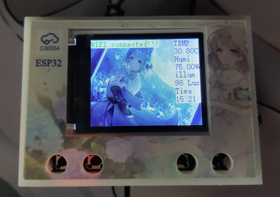
Based on the LCSC ESP32 S3 development board and using the ESP IDF as the development environment, a simple desktop assistant was created to achieve WiFi connectivity, remote air conditioner on/off control, temperature and humidity monitoring and uploading, and time display functions.
1. Function Introduction
This project was designed and built using the LCSC ESP32 S3 development board. Currently, it has achieved WiFi connectivity, remote air conditioner on/off control, temperature and humidity monitoring and uploading, time display, and cloud-based intelligent APP interface display and control functions.
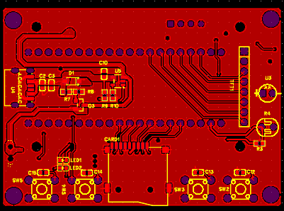
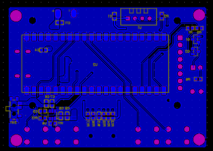
2. Schematic Diagram Explanation
2.1 Power Supply Circuit
The power supply adopts a USB + lithium battery power supply scheme. When the USB socket is plugged in, the system is powered by the USB and charges the lithium battery; when the USB socket is unplugged, the power circuit is powered by the lithium battery.
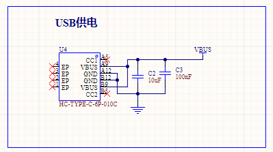
USB power supply interface Lithium battery charging circuit
2.2 Automatic Switching of Power Supply Circuit
The key to achieving automatic switching of the power supply circuit is the use of a PNP type MOSFET. The
voltage Vgs of the MOSFET determines the on/off state of the circuit. When powered by USB, the potential at point G of the PNP transistor is pulled high by the voltage divider resistor, Vgs > 0, the MOSFET is cut off, and the lithium battery does not supply power. When only the lithium battery is powered, point G is grounded, the voltage is 0V, the Vgs
transistor is turned on, and a Schottky diode is connected at the USB output to prevent the two circuits from interfering with each other.

The power supply switching circuit
2.3
includes a 5V boost circuit. The ESP32S3 development board has a 3.3V LDO. Considering the instability of the lithium battery, a 5V boost regulator circuit is designed in the circuit to stabilize the voltage and maintain stable device operation. The boost chip selected is the Chipstar X4310, which outputs a fixed 5V when the input is 2.7~5V,
providing a stable voltage for chip operation. 2.4 Lithium Battery

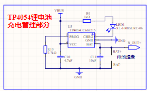
Charging
Management Circuit
: Regarding the lithium battery charging and discharging circuit, the commonly used TP4054 charging and discharging management chip was used. The maximum charging current is 500mA, and this current can be adjusted by changing the resistor. During charging, pin 1 of the chip is grounded, and the LED lights up. When the battery is fully charged,
pin 1 switches to a high state, and the LED turns off. The battery charging status can be determined by the LED's on/off state. 2.5 Display
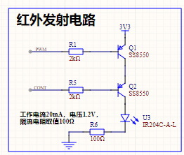
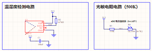
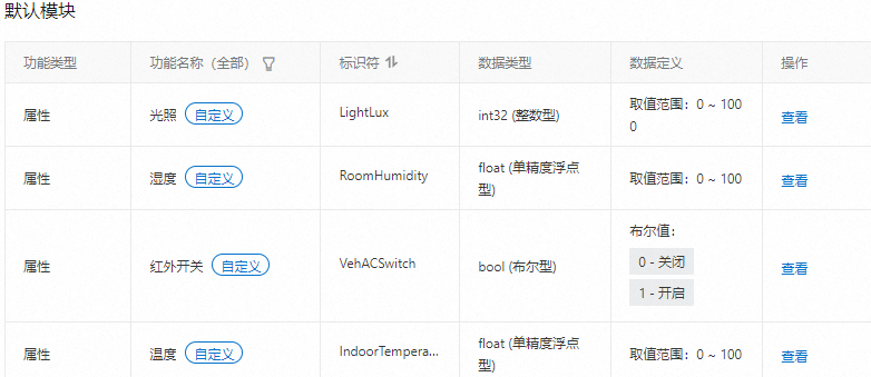
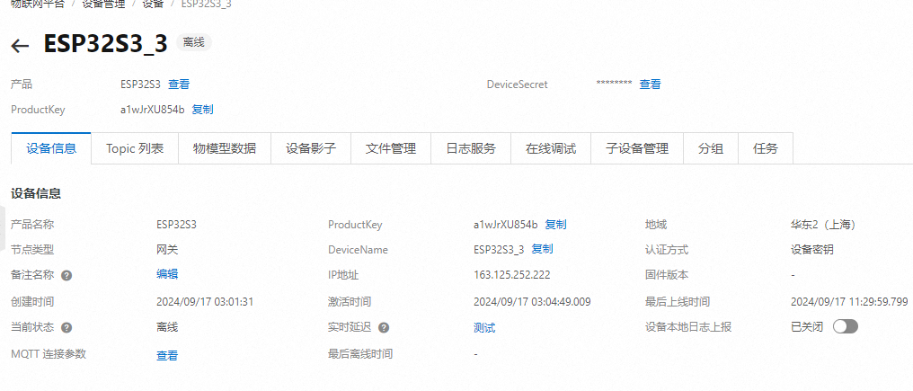
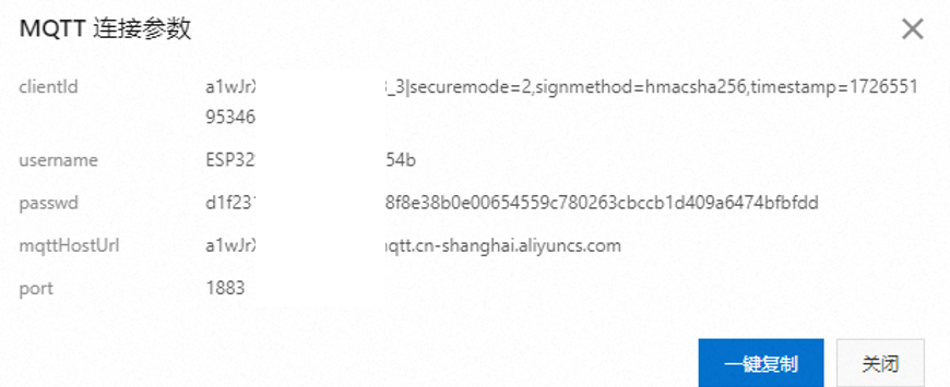
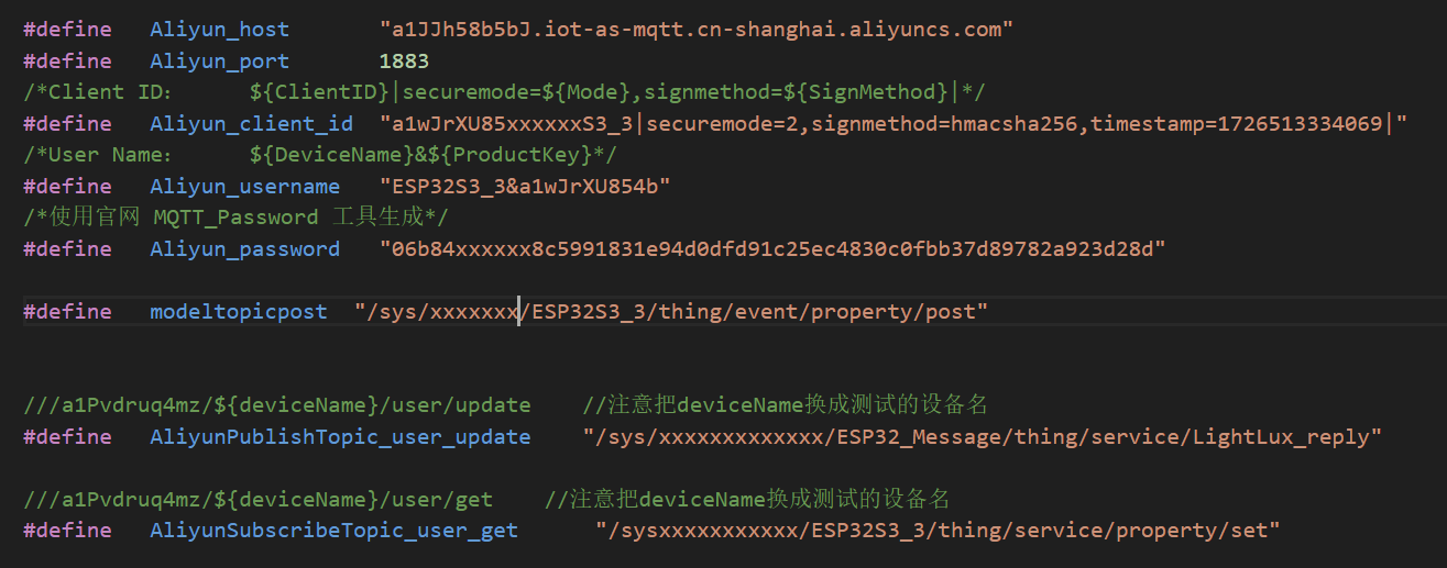
Circuit: The display circuit uses a 1.8-inch OLED screen. This screen uses an SPI interface for communication, resulting in a stable refresh rate and good display quality. 2.6 Infrared Transmitting Circuit: According to the Espressif official manual, the ESP32S3 has infrared functionality and can transmit infrared signals through configuration functions. However, after verification, the transmitted infrared signal is only 32 bits (refer to the Espressif official API for details). However, actual measurements showed that the air conditioner remote control sends signals of over 100 bits at a time. Therefore, after multiple attempts, this solution was abandoned. Therefore, the infrared emitting circuit in this project uses a timer to output a 38kHz PWM waveform to simulate the infrared NEC protocol. The circuit is controlled by two I/O ports: one for enabling the signal and the other for transmitting the signal. All I/O ports are controlled by PNP transistors to turn on and off, and the NEC protocol is simulated through encoding. 2.7 Temperature, Humidity, and Light Detection Circuit : The temperature and humidity sensor uses the cost-effective DHT11, costing less than two yuan per sensor. Light detection uses a photoresistor voltage divider, and then the voltage is read and converted by an ADC. 3. Physical Image of the Temperature, Humidity, and Light Detection Circuit : [Image of the physical product and its display on the cloud smart APP] 4. PCB Design Notes: In the PCB design, the power supply traces should be thickened, and copper pours should be used for connections when necessary. 5. Key Program Descriptions 5.1 The Alibaba Cloud platform access project uses the MQTT protocol to connect to Alibaba Cloud. Before writing the program, you need to register an account on the Alibaba Cloud IoT platform, create products and devices, and define product functions: Alibaba Cloud Platform Product Creation Alibaba Cloud Platform Function Definition Alibaba Cloud Platform Device Creation After the device is created, we can obtain the MQTT connection parameters and the Topic list used for attribute subscription and publication: MQTT Connection Parameters Topic List Write the above information into the code as follows: After writing the information into the code , connect to WIFI and use the mqtt_app_start() function to initialize and connect the device to Alibaba Cloud. 5.2 Alibaba Cloud Message Subscription and Publication After writing the Topic list into the program as described in 5.1, we can create messages using cJSON and then call the esp_mqtt_client_publish function to publish the message:


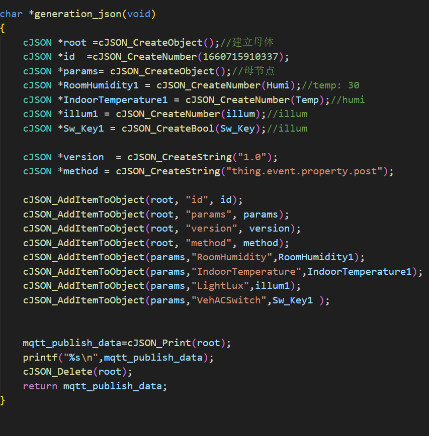
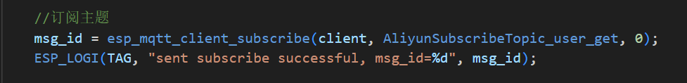
Note that when publishing messages, the variable names on our local machine must be consistent with those set on Alibaba Cloud to ensure that Alibaba Cloud can recognize the information we publish. As for subscribing to topics,
simply add the relevant Topic list during initialization. After receiving a subscription, the relevant message will be printed to the console. Alternatively, we can use cJSON to parse the message and
obtain the content we need.
5.3 Infrared Signal Transmission
The infrared signal uses a PWM waveform generated by a timer to simulate NEC timing for information transmission. The relevant timing definitions are as follows:
Logic 1 and Logic 0:

Logic "0": 560µs effective pulse + 560µs idle interval, total duration 1.12ms. Logic "1": 560µs effective pulse + 1.68ms idle interval, total duration 2.24ms (twice that of Logic 0).
Start Code:

The start flag sequence for each frame is: a 9ms AGC pulse (16 times the 560µs pulse used for logic data bits) + 4.5ms idle.
Therefore, based on the above information, the NEC waveform can be simulated as follows:


Once the relevant code is determined, a signal can be sent through the ESP32's IO port to control the air conditioner's on/off state. The question then arises: how to determine the air conditioner control code?
If the air conditioner brand is commonly used, you can search online; you might find it. If it's less commonly used, or an older model, such as the air conditioner this project
requires control, then use an oscilloscope to measure it!

The image above shows the infrared receiver output waveform tested with an oscilloscope when the air conditioner is turned on. The power-on code information can be obtained through protocol analysis.
(Actually, it's not that complicated. You only need an infrared decoder, connected to a microcontroller, and an infrared receiver code ported from the internet. The oscilloscope is mainly used for convenient waveform observation during debugging.)
6. Assembly Instructions:
All resistors and capacitors in this project use 0603 packages. Only the chip soldering is relatively difficult; with a few attempts, you can complete the soldering. After the code is burned, install the product into the casing. Note that there are four 1.8mm diameter posts for positioning at the screen; do not break them.
3D Shell Files.zip
Demo video.mp4
code.7z
PDF_ESP32 Desktop Assistant.zip
Altium_ESP32 Desktop Assistant.zip
PADS_ESP32 Desktop Assistant.zip
BOM_ESP32 Desktop A


 京公网安备 11010802033920号

 TH72012


