Video Link:
https://www.bilibili.com/video/BV1jb421e7V6/?spm_id_from=333.999.0.0&vd_source=0f4f047c9f645f8d80a94c78c947d2c7
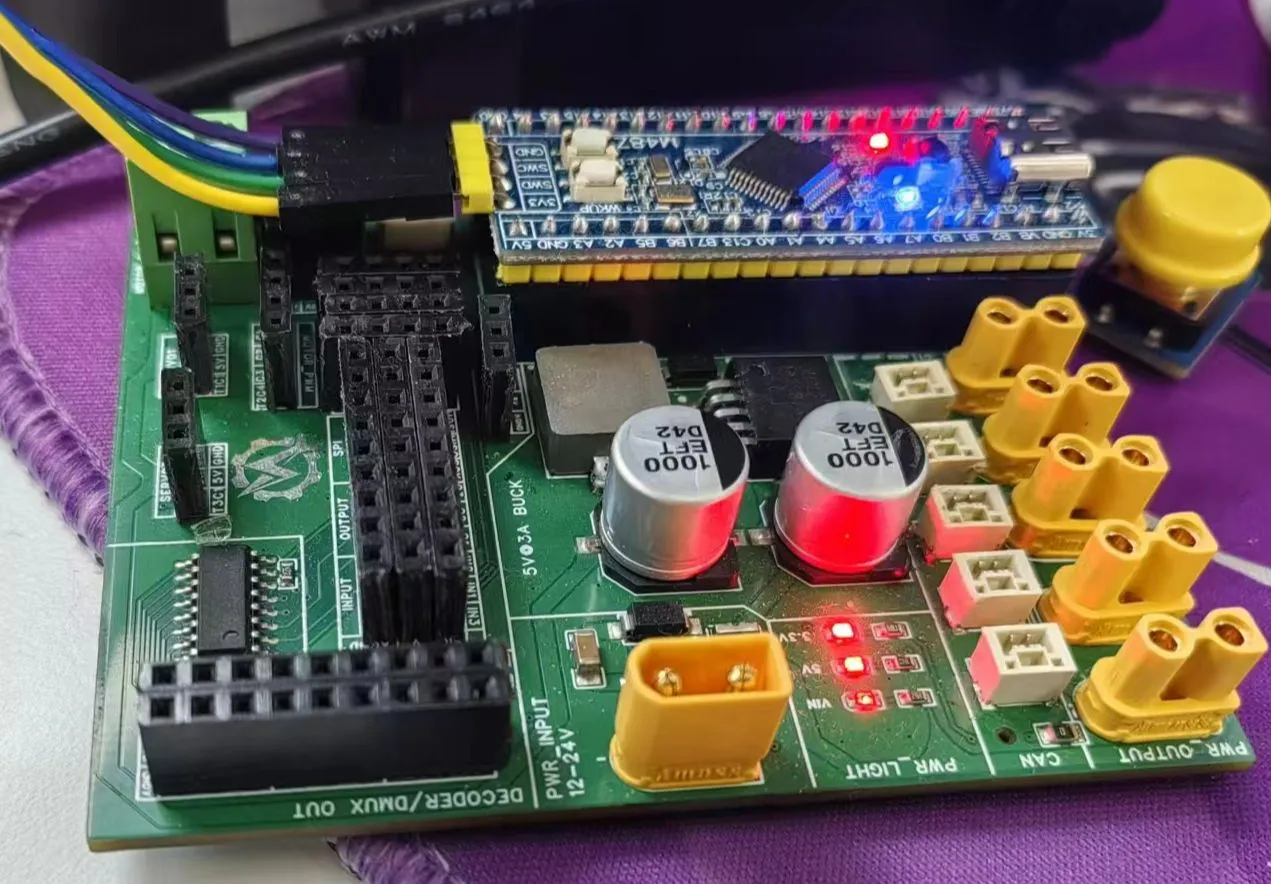
This project is an STM32 carrier board designed by the Magician team at ShanghaiTech University for the 2024 National Electronic Design Contest (NCDC) control problem training and competition. After being fortunate enough to achieve first place in the NCDC control problem with two senior students in 2023, the Magician team began to be responsible for the training and preparation of control-related problems in the school's NCDC. To enable team members or other interested students to quickly get started with embedded tasks, and to ensure module reusability during the competition, this project uses the Zhengdian Atom M48Z STM32F103C8T6 minimum system board, and brings out the basic peripherals.
Because it was urgently needed for training, the preparation time was less than a week. Furthermore, the author's hardware engineering experience is relatively limited. Therefore, this project has some design flaws in certain aspects, which will be explained in detail later. Your understanding is appreciated!
Peripheral Interface:
This project is mainly based on the Zhengdian M48Z minimum system board, configuring and bringing out commonly used peripherals. These include 7 TIM channels, 1 CAN channel, 2 UART channels, 4 ADC channels, 1 I2C channel, 1 SPI channel, and several GPIO INPUT/OUTPUT.
Project Parameters
: 1. Regarding the power
input: It is a wide-range input of 12-24V with reverse connection protection and 2A current limiting (depending on the resettable fuse). The input is stepped down through an LM2596S-5.0 to power the servo motor and DC motor. Given the very low performance of the 2596 (nominal 3A), it may not be sufficient and has a large footprint. Future solutions plan to replace it with a TMI3351 or LM3150.
In addition, to ensure the normal power supply of the CAN transceiver and MCU, we used two wide-input LDOs, MD8350A and MD8333A. When purchasing materials, please pay attention to the model number containing "A" (as the pins differ depending on whether "A" is included, making a mistake will cause the chip to burn out).
It is worth noting that an oversight during the design resulted in the silkscreen markings for the 5V and GND of the DC motor power supply port being reversed; please correct this.
2. Regarding UART:
To adapt to the DBUS interface of the DR16 receiver, the board has a built-in BJT inverting circuit, and only Tx is brought out, providing 5V power. The other UART works normally.
3. Regarding the I2C1 and T3C2 conflict
: The I2C1 was brought out for possible functions such as reading and writing EEPROM, driving the LCD, or receiving I2C ranging feedback packets. After failing during testing, it was only through the errata manual that it was learned that the clock of T3C2 of the F103C8T6 conflicts with that of I2C1. Once I2C1 is EN, T3C2 will output a constant high level (this issue is quite coincidental). The T3C2 is used as the buzzer drive signal, and its DC output could cause it to burn out, so only one of the two can be selected. When this problem was discovered, the board had already been surface-mounted, so the only option was to temporarily disable I2C1 while retaining the normal buzzer function.
4. Regarding GPIO multiplexing:
Given the limited pin resources of the C8T6, the project used a 74HC238 decoder, but its effectiveness was limited. Surface mounting and pinouts can be adjusted as needed. In later versions, we replaced it with a 64-pin F412, making the related multiplexing unnecessary.
5. Regarding CAN:
To facilitate more precise and efficient control of brushless DC motors from companies like DJI or DM for experienced users, we have reserved five XT30 power supplies and GH1.25 * 2p pinouts on the board. The XT30 is directly connected to the power input; the GH1.25 uses DJI's CAN wiring sequence. If using motors from companies like DM, remember to swap the wiring sequence.
In summary and looking
ahead, due to various reasons, the board that should have been completed two months before the electronics competition has been delayed until now, and we sincerely apologize for that. There are also many shortcomings and areas for improvement in this project, and we hope to do better in the next iteration. The Magician team will also use the newly designed carrier board and minimum system board as much as possible in the 2025 season's intramural competition, providing a better hands-on experience for newcomers and laying the foundation for future self-made control boards that replace the C board. We will also open-source the relevant boards after verification, and welcome everyone's feedback. Thank you! Regarding
the software code,
since it is only a carrier board or power distribution board, only the CubeMX configuration file is provided here.


 京公网安备 11010802033920号

 MX1N5274DE3TR


