

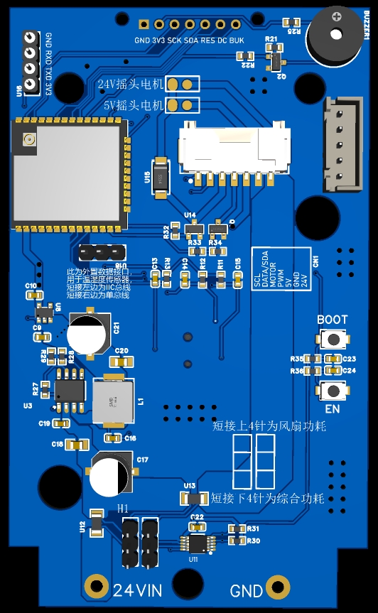
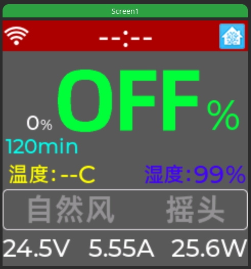
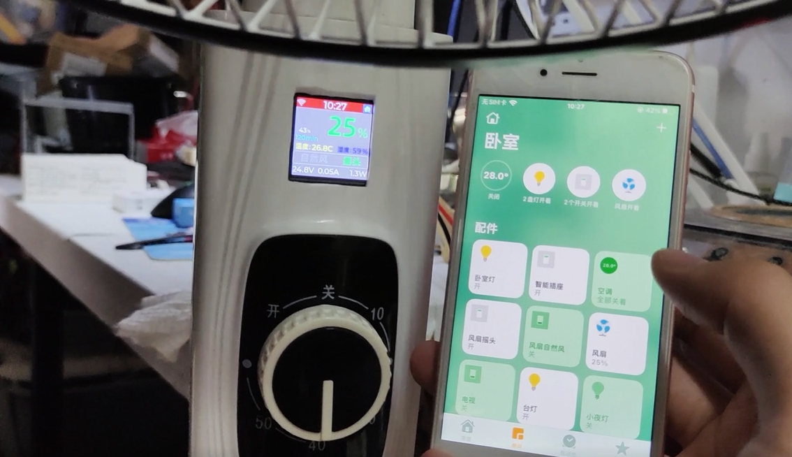
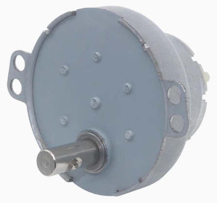
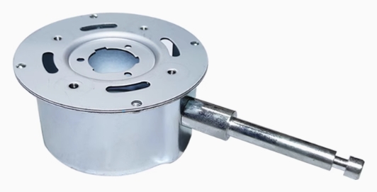
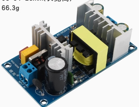
 it uses a Jinyichen 1.33-inch 240x240 resolution LCD display, but other displays with the same pin SPI protocol can also be used; the screen can display WiFi signal strength, current time, Home Assistant connection status, memory wind speed, current wind speed, timer, temperature and humidity, blowing mode, oscillation mode, power supply voltage, current, power, etc.; it selects the DHT11 fully digital single-bus temperature and humidity sensor, which has a wide temperature measurement range and can meet general needs; higher precision sensors such as the I2C protocol SHT20 can also be selected, and the bus protocol can be selected via jumper; the sensor power supply can be drawn from the 5V power supply of the motor. The EC11 controller supports rotation, short press, long press, and double-click actions for power on/off, fan speed adjustment, oscillation, and natural wind control. It uses an INA226 power acquisition chip to collect power consumption data, and a jumper can be used to select whether to display system power consumption or brushless motor power consumption. For hardware, a 24V brushless motor with built-in driver and PWM speed control is required. A brake is optional, but this solution does not utilize it. Most brushless motors support forward and reverse rotation, but reverse rotation is useless for household fans, so this solution does not use it (I really can't think of any use for a fan in reverse, for takeoff?). I personally used a Nidec 48704R130 motor, which is quite suitable for modification in terms of size, power, and speed. The only drawback is its short motor shaft, requiring modification of the original fan's plastic parts. Accessories are also relatively easy to select. Of course, other suitable brushless motors can also be chosen. The PWM frequency can be changed in the code to adapt to different driver boards. For the power supply, a 24V AC-DC power module is required. The module size should be selected based on the motor's power, generally not less than 3A of rated output current (3A current under 24V power supply is already 72W, which is a very powerful airflow for a brushless motor with 16-inch blades). The module size also needs to be considered to ensure it fits in your fan housing. This solution uses an independent oscillating motor, which can be powered by 5V or 24V. A oscillating arm speed of 3-10 r/min is generally suitable. $color{blue}{Hardware Specifications}$ (For reference only) Brushless motor: Nidec 48704R130 motor Oscillating motor: 5V or 24V, must have a fixing hole in the middle of the shaft. Motor bracket Power module $color{blue}{Precautions}$ The specific hardware selection needs to be determined based on the appearance design of the fan to be modified and the available space. Alternatively, you can simply and directly externalize each module (provided safety is ensured). The temperature and humidity sensor can be externally mounted behind the fan motor, taking GND and 5V power from the brushless motor and connecting to the ESP32 via the SCL and DATA/SDA communication lines reserved on the motor cable. A ready-made 7-pin PA/PAE cable can be purchased; note that the wire diameter should not be too thin, at least 24awg, or it can be made yourself. The motherboard has a reserved UART programming interface, I2C and single-bus jumpers for the temperature and humidity sensor, and an INA226 power acquisition jumper, allowing selection of overall power consumption or individual motor power consumption; two GPIOs are also reserved for other uses. The implemented functionality is simple, so a WiFi selection interface is not provided on the display; you must manually set the WiFi name and password in the code. Similarly, you need to change your own HomeAssistant address and MQTT user password in the code. The BOM exported from LCSC EDA should be used as the standard; the BOM automatically generated by the system may not be accurate. Please go to Bilibili to watch the assembly process. Bilibili video -- Function demonstration and introduction. Since the appearance and design of fans from different brands are different, it is impossible to provide a specific modification and assembly plan. You can refer to the ideas in my video to modify and assemble it yourself.


All reference designs on this site are sourced from major semiconductor manufacturers or collected online for learning and research. The copyright belongs to the semiconductor manufacturer or the original author. If you believe that the reference design of this site infringes upon your relevant rights and interests, please send us a rights notice. As a neutral platform service provider, we will take measures to delete the relevant content in accordance with relevant laws after receiving the relevant notice from the rights holder. Please send relevant notifications to email: bbs_service@eeworld.com.cn.
It is your responsibility to test the circuit yourself and determine its suitability for you. EEWorld will not be liable for direct, indirect, special, incidental, consequential or punitive damages arising from any cause or anything connected to any reference design used.
Supported by EEWorld Datasheet
EEWorld
subscription
account

EEWorld
service
account

Automotive
development
community

Robot
development
community

About Us Customer Service Contact Information Datasheet Sitemap LatestNews


Room 1530, 15th Floor, Building B,
No.18 Zhongguancun Street,
Haidian District,
Beijing, Postal Code: 100190
China
Telephone: 008610 8235 0740
 京公网安备 11010802033920号

 183-183-001L999


