In the process of redevelopment,
we often need to supply different power voltages to the system, but the commonly used ones are always the same few. Therefore, we often rely heavily on DC power supply boxes. However, owning a power supply box is relatively expensive and inconvenient to carry. So, after learning about PD (Power Distribution Module) triggering, I decided to make a multi-voltage output, compact, convenient, and low-cost power output board.
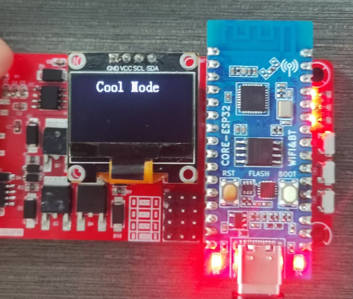
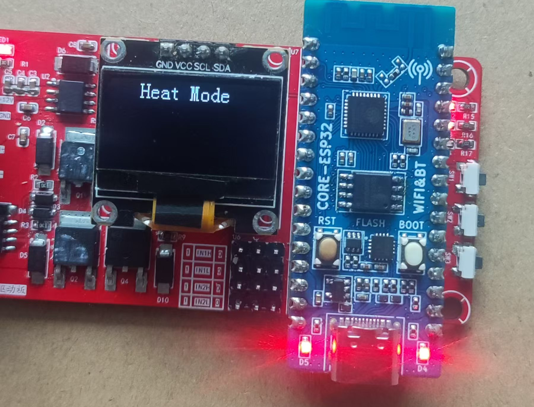
The semiconductor cooling/heating cup holder I made last time did not achieve forward and reverse rotation due to a mistake in the bootstrap circuit design. So, I made it this time as well. The driver board can also be used to drive motors or other loads. The power supply will be a 12V output from the PD triggering. For
the PD-triggered power output board, I prepared two solutions: one with a 3.3V output and the other with a voltage output only supported by the PD protocol. Adding a step-down circuit would significantly increase the board's size; I wanted a very compact board, similar in size to a USB-to-serial module. I'm using resistor configuration because level configuration requires CFG2 and CFG3 to be around 3.3V, necessitating a step-down circuit to obtain this 3.3V. Therefore, I've included a level configuration interface (not yet verified) on the 3.3V version of the power output board. ( The product was returned. ) It's smaller than I imagined =_= I even added a casing. I had a coupon, so I didn't use it. After testing, 9V, 15V, and 20V all output normally. 5V requires connection to a computer or a charger that doesn't support PD triggering. However, the 12V output becomes 15V. Hardware checks are fine; I suspect the plug doesn't support 12V output. The plug vaguely says 6-20V. But my driver board is 12V powered. There's no way around it; I still have to use a power supply box. The motor driver board description includes 12V to 3.3V (for microcontrollers), and an H-bridge circuit (to achieve positive...). The circuit includes a current sampling circuit, a main control chip, an OLED interface, and three LEDs and three buttons. I reserved an interface for testing the EG2312. Last time, when testing with DuPont wires, I accidentally touched a nearby pin and broke the chip. This time, I carefully verified that after powering on, the EG2312 tested normally via the header pins. This chip has a built-in protection mechanism and will not experience a short circuit due to simultaneous conduction of the upper and lower terminals. Later, I used a 50% duty cycle to control the upper (positive) MOSFET, and the phenomenon was normal. However, when I controlled the lower (negative) terminal, the HO output immediately cut off after a short while. The reason is unknown, but I guess it's due to timing mismatch, which I interpreted as a short circuit due to simultaneous conduction of the upper and lower terminals, causing it to stop working. For the initial load test, I used a thermoelectric cooler with a thermometer for a more intuitive digital temperature display. Here, I only gave it a 50% duty cycle, meaning the cooler operates at 6V. Full operation would yield better results. Current sampling:........................ Thermistor feedback:..........................................................

![]()


 京公网安备 11010802033920号

 NX8566LE6023-CC


