Project Introduction:
This project is a desktop assistant based on the ESP32C3 microcontroller. It features temperature and humidity detection, real-time network time monitoring, and the ability to send temperature and humidity data to an MQTT server via the MQTT protocol. (Due to this being the first time working with Espressif's ESP32 series chips, other functions are not yet added.)
Project Functionality
: This design is a desktop assistant based on the ESP32C3 series microcontroller. It has three independent buttons, whose functions are not yet added. It can acquire real-time temperature and humidity and network time, and can subscribe to receive temperature and humidity data via an MQTT client.
Project Parameters
: This design uses a CH343G USB converter chip. Automatic reset and download are achieved by connecting the DTS and DTR pins to an NPN transistor and then connecting them to the EN and BOOT pins of the ESP32C3 chip.
This design uses a 1.8-inch 4-wire SPI interface with an ST7735S controller. The TFT screen displays temperature and humidity icons, temperature and humidity data, and real-time network time using LVGL.
A fully digital DHT11 temperature and humidity sensor with a wide temperature measurement range is selected to meet general needs.
Temperature and humidity data are uploaded to the MQTT server every 2 seconds (can be modified in the code).
Principle Analysis (Hardware Description):
This project consists of the following parts: power supply, CH340G automatic download section, main control section, temperature and humidity detection section, and display section.


Figure 1--Power Supply Circuit:
Two TYPE-C-16P interfaces are used as power supply interfaces. One TYPE-C pin is connected to the corresponding USB data pin of the CH340G (UD+), (UD-). The CH340G's automatic download circuit can be used to download or debug the ESP32C3 program. The other TYPE-C pin is connected to the ESP32C3's USB_D+, USB_D-. USB is used directly for downloading and debugging without conversion to a serial port signal. (Not tested, but this TYPE-C port can provide power when the other port is underpowered.) Both TYPE-C ports have 5.1K pull-down resistors added to the CC1 and CC2 pins to facilitate identification and configuration by different hosts.
Figure 2 - CH340G Automatic Download Circuit;
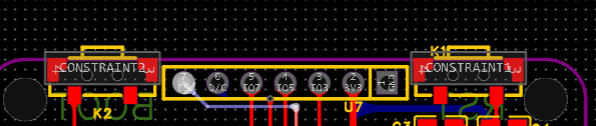
Figure 3 - Main Control Section;

Figure 4 - Temperature and Humidity Detection Section:
This section can be modified according to the device used;
Figure 5 - Display Section:
Uses a 7-pin header (no backlight). If backlight is required, add a 1-pin
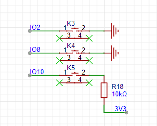
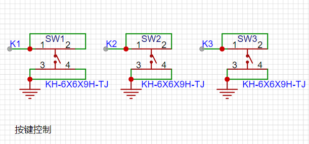
header; Figure 6 - Button Section:
In the three buttons in the above figure, K3 (IO2) and K4 (IO8) must be pull-up. See the official ESP32 documentation for details.
The two buttons in the lower figure are the BOOT button and the EN (RST) button.
The software code
was compiled using ESP-IDF version 5.2.0 compiler under a Linux virtual machine, using VS CODE to remotely log in via SSH to write the code. The code is modified from spi_lcd_touch in ESP-IDF. See the attachment for detailed code.
The MQTT client software is the open-source MQTTX. Software download address;
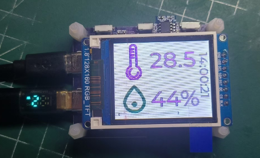
physical picture;
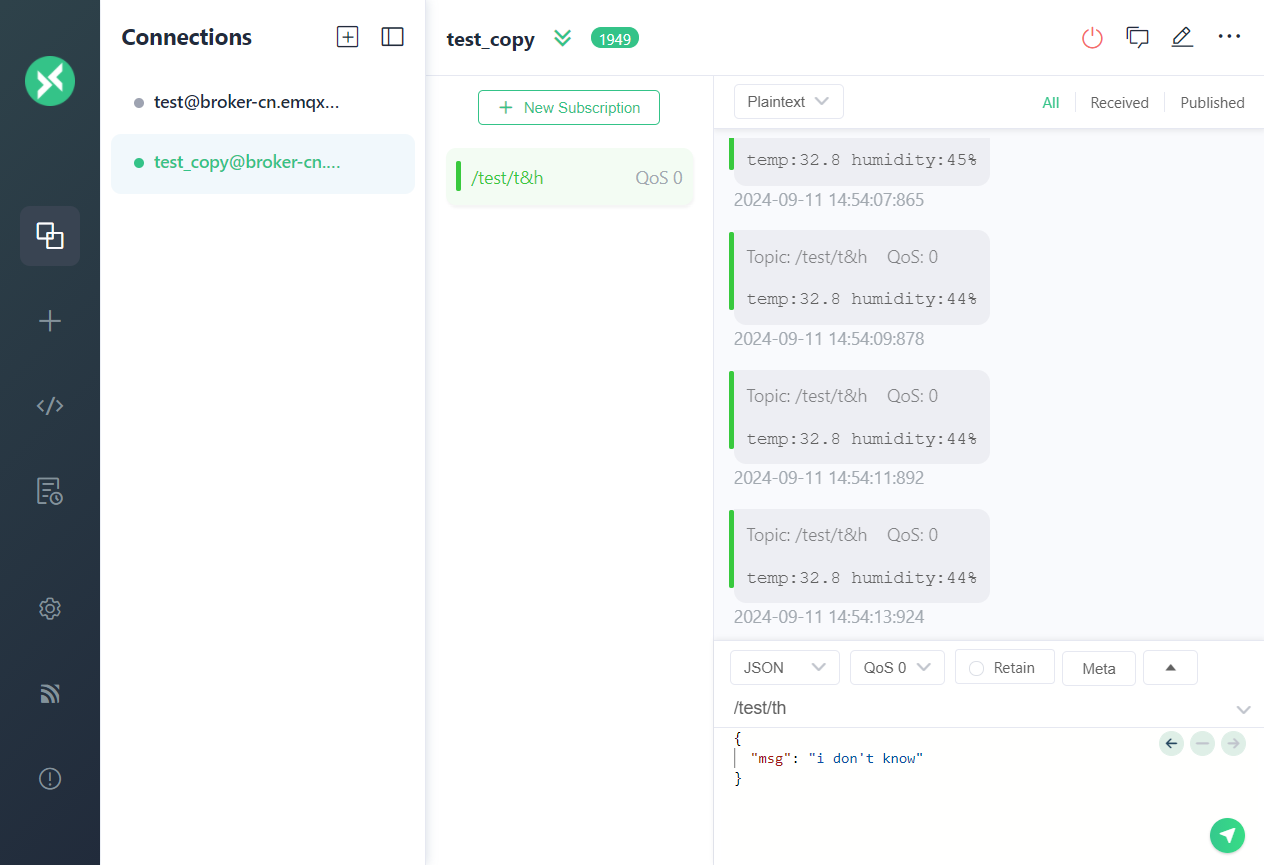
MQTT client screenshot.
project.zip
PDF_ESP32-based Desktop Assistant.zip
Altium - A Desktop Assistant Based on ESP32.zip
PADS_ESP32-based Desktop Assistant.zip
BOM_ESP32-based Desktop Assistant.xlsx
92307
Topzhu A1/A1mini Series Fan Expansion Board
This is an expansion board for the extruder cooling fan interface of the A1/A1mini.
This is an expansion board for the extruder cooling fan interface of the A1/A1mini. It can separate the hot-end fan's wiring to power an additional fan.
You only need a 5V two-wire fan (for three-wire or four-wire fans, you need to remove the wires except VCC/GND).
The board comes in two versions: a speed-enhancing version that can double the speed of the hot-end fan. The hot-end fan of the Tuozhu A1 series only runs at 30% speed; using the speed-enhancing version will double the speed.
Regardless of whether it's speed-enhancing or not, the control strategy for the additional fan is "once the hot-end fan starts, it runs at full power." Therefore, when choosing a fan, please select one with good dynamic balance, minimal noise and vibration, and use foam adhesive to attach the fan to the extruder to reduce the impact of fan vibration on print quality.
I have designed a mounting bracket for a 4cm fan, which can be downloaded from Tuozhu MakerWorld.
Please note that this project is prohibited from commercial use. You can use it yourself, but you cannot sell it! If you really want to sell it, please contact me for commercial permission! Please do not use it for commercial purposes without permission! !
WeChat_20240911141557.mp4
WeChat image_20240911141551.jpg
WeChat image_20240911141546 - copy.jpg
WeChat image_20240911141542.jpg
PDF_Toozhu A1-A1mini Series Fan Expansion Board.zip
Altium_Tuzhu A1_A1mini Series Fan Expansion Board.zip
PADS_Tokuzu A1_A1mini Series Fan Expansion Board.zip
BOM_Toozhu A1_A1mini Series Fan Expansion Board.xlsx
92308
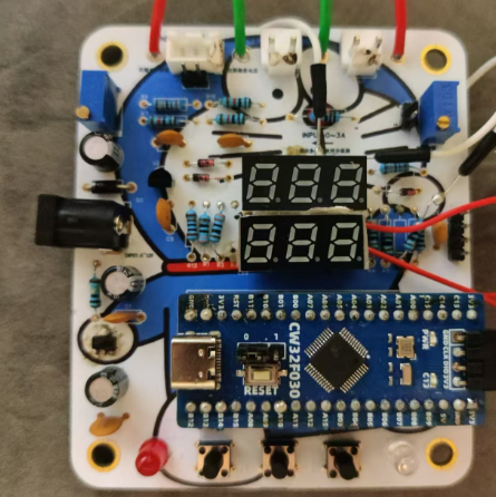
CW32 Voltage and Current Meter
This project is a voltage and current meter project based on the CW32 microcontroller, which aims to improve my development skills from multiple dimensions.
Project Introduction:
ADC is an indispensable key component in electronic systems, enabling analog-to-digital conversion and providing methods for digital processing and analysis. Digital voltmeters and ammeters combine ADC technology with circuit measurement principles, accurately converting analog voltage and current signals into digital information for easy reading and analysis, making them a powerful tool for product hardware analysis. In product applications, digital voltmeters ensure the accuracy and safety of circuit design, while also providing strong support for product quality control and subsequent maintenance. This
project is a voltmeter and ammeter project based on the CW32 microcontroller, aiming to improve development capabilities from multiple dimensions.
Hardware Design:
1. Power Supply Module:
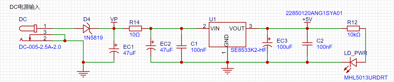
LDO power supply is used here, offering advantages such as low ripple, small size, and low price. Referring to the power supply methods and application scenarios of existing finished voltmeters and ammeters, the SE8550K2 was selected as the power supply, with a maximum input voltage of 40V, meeting the requirements of most meter products.
2. Main Controller Selection
: This paper uses the Diwenxing CW32F030C8Tx minimum system board as the main controller. The selection of the controller is crucial to the overall success of the project; therefore, it is extremely important. Multiple factors must be considered to ensure the chosen controller meets the requirements and is reasonably priced.
Thus, the first step is to meet the project's needs: understand the required computing power, including clock speed, whether floating-point operations are required, memory requirements, etc. It's also necessary to determine the required number of I/O ports and important peripherals, such as ADCs and TIMs. Since the primary purpose of this project is learning, there are no major hardware restrictions, resulting in some cost overruns.
The reasons for choosing Cw as the main controller are as follows:
Wide operating temperature: -40~105℃;
Wide operating voltage: 1.65V~5.5V;
Strong anti-interference: HBM ESD 8KV; All ESD reliability meets the highest international standards;
Stable and reliable eFLASH technology;
Key project focus - Better ADC: 12-bit high-speed ADC with ±1.0LSB INL 11.3ENOB; Multiple Vref reference voltages;
Compared to equivalent ST products on the market, it exhibits superior performance.
3. Voltage and Current Sampling Circuit:
This project uses a 220K+10K voltage divider resistor, resulting in a voltage division ratio of 22:1.
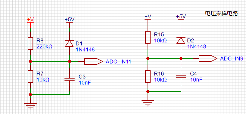
For
safety during debugging and learning, 30V was chosen as the maximum measured voltage, conforming to human safety standards.
The ADC reference voltage is 1.5V, which can be configured programmatically. To reduce power consumption in the sampling circuit, R7 was chosen as 10k based on experience. The high-side resistor R8 can then be calculated using the above formula. The voltage
division ratio is calculated as: ADC reference voltage / design input voltage. Based on the design parameters, 1.5V/30V = 0.05.
Similarly, the high-side resistor can be calculated using the voltage division ratio: 10K/0.05 = 200K. A standard resistor slightly higher than the calculated value was chosen, a 220K E24 series resistor.
The ADC reference voltage is calculated as follows: 1.5V/30V = 0.05, which is the input voltage.
The high-side resistance is calculated as: the low-side resistance/voltage divider ratio, which is calculated as: 10K/0.05 = 200K, which is the voltage divider
ratio. A standard resistor is selected: a resistor slightly higher than the calculated value of 200K is chosen. Typically, E24 series resistors are selected; therefore, in this project, 220K is chosen as the closest value to 200K. Range
switching
is also included in this project to explore the advantages of range switching in improving accuracy. In practice, multimeters often have multiple ranges for more accurate measurements; by adjusting different ranges, the optimal measurement accuracy of the measured point within the corresponding range can be obtained. This project uses a combination of hardware and software. First, ADC_IN11 is used to measure voltages below 30V. If voltages between 0 and 3V are to be measured, the ADC_IN9 channel is used to improve measurement accuracy.
4. The current sampling circuit
project uses a low-side current sampling circuit for current detection.
When learning and debugging, the low-side of the sampling circuit shares a common ground with the development board's meter interface, and R0 is not soldered.

The project's designed sampling current range is 0~3A. A resistor with 1% accuracy and a resistance of 100mΩ is selected as the sampling resistor. The following aspects need to be considered when selecting it:
the maximum value of the designed measurement current (3A in this project);
the voltage difference introduced by the sampling resistor (generally less than 0.5V);
the power consumption of the sampling resistor; based on the design parameters, a 1W metal-wound resistor was selected; and
the voltage multiplier across the sampling resistor. In this project, no operational amplifier is used to build the amplification circuit; the gain is 1. The selection of the sampling resistor can then be derived from the above parameters.
In high-current scenarios, the sampling resistor R0 can be replaced with a shunt for more practical use. Because this project is only for learning purposes, currents exceeding 3A will not be discussed in detail, but the selection principle remains the same.
5. Digital Tube Display:

Due to an oversight in drawing the schematic, one segment code from two common-cathode digital tubes was connected together, while the segment codes were separated. This is something that requires special attention. It took a long time to troubleshoot, and I had to use flying wires to solve the problem. There are many references for connecting common cathode and common anode digital tubes; I will only briefly mention them here. Choosing digital tubes to display current and voltage values better meets the needs of learning and debugging, and their cost and performance are both good.
In the project, actual testing showed that a 300Ω value for the current-limiting resistors (R1~R6) resulted in good brightness and non-glaring visibility of the digital tubes.
6. Power Indicator
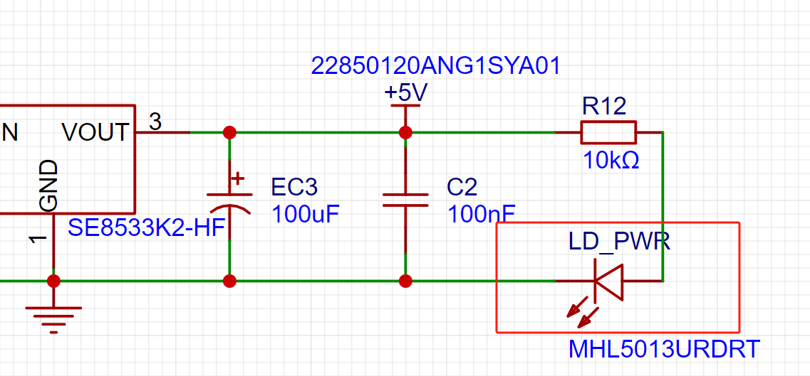
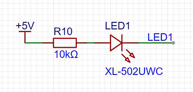
LD_PWR: This is the power indicator. Since the chip's I/O ports often have a greater sinking capacity than a sourcing capacity, LED1 is designed to be active low (on). To reduce LED power consumption, some LED brightness was sacrificed, and a 10K current-limiting resistor was chosen for the LED.
7. The button circuit design
benefits from the CW32's ability to configure internal pull-up and pull-down resistors on the I/O port, eliminating the need for special external configuration. One end of the button is connected to the MCU's I/O port, and the other end is grounded. When the button is pressed, the I/O port is pulled low; the MCU detects the level change in the I/O port to trigger the corresponding function.
8. The TL431 circuit design
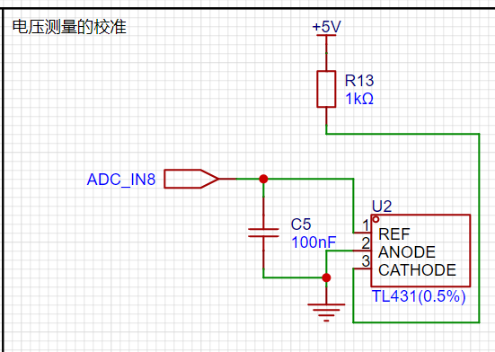
project adds an additional TL431 circuit to provide a 2.5V reference voltage for calibrating the external voltage of the AD converter. This circuit is not essential for the product; it is only used here for learning related applications.
The TL431 has the following advantages:
Precision: Its output voltage is very accurate. The TL431 used in the project has an accuracy of ±0.5%; at room temperature, the measured voltage on the board was 2.495V. Compared to common Zener diodes, its accuracy is significantly superior.
Adjustable output voltage: The output voltage adjustment range is Vref~36V, with Vref voltage approximately 2.5V.
Sinking current capability: This refers to how much current the output voltage pin can provide, which is greatly related to the resistance value (R13) and should not be less than 1mA. If there is no need for sinking current, do not design the current to be too large, as this will cause unnecessary power consumption.
Attached is an article on using JLink to program the CW32 microcontroller; it's very practical!!!
https://mp.weixin.qq.com/s/YBpDoOwrKUAyx7UVfEe6zw
Figure
1:
Ignoring the flying wires—this is the price of careless schematic drawing!!!
Figures 2 and 3:
Measuring standard 3.3V and 5V voltages with minimal error.
This project was completed with reference to the JLCPCB CW32 training camp; many thanks to them!
Current and Voltmeter Engineering Code.rar
PDF_CW32 Voltage and Current Meter.zip
Altium_CW32 voltage and current meter.zip
PADS_CW32 Voltage and Current Meter.zip
BOM_CW32 Voltage and Current Meter.xlsx
92309
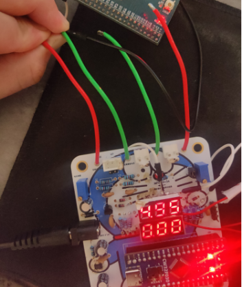
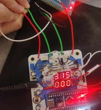
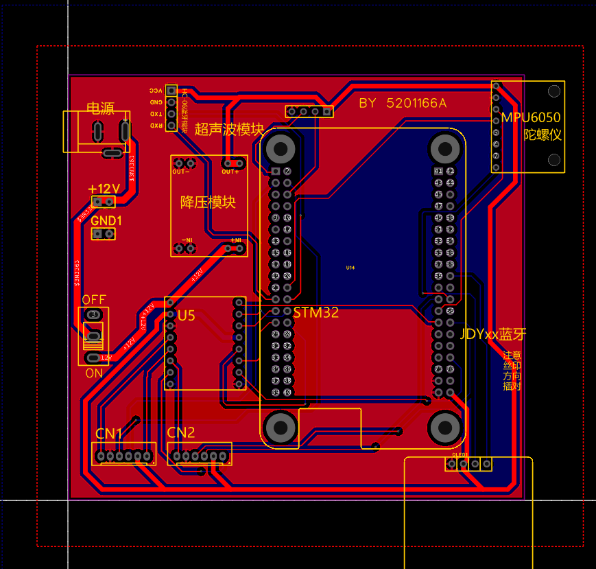
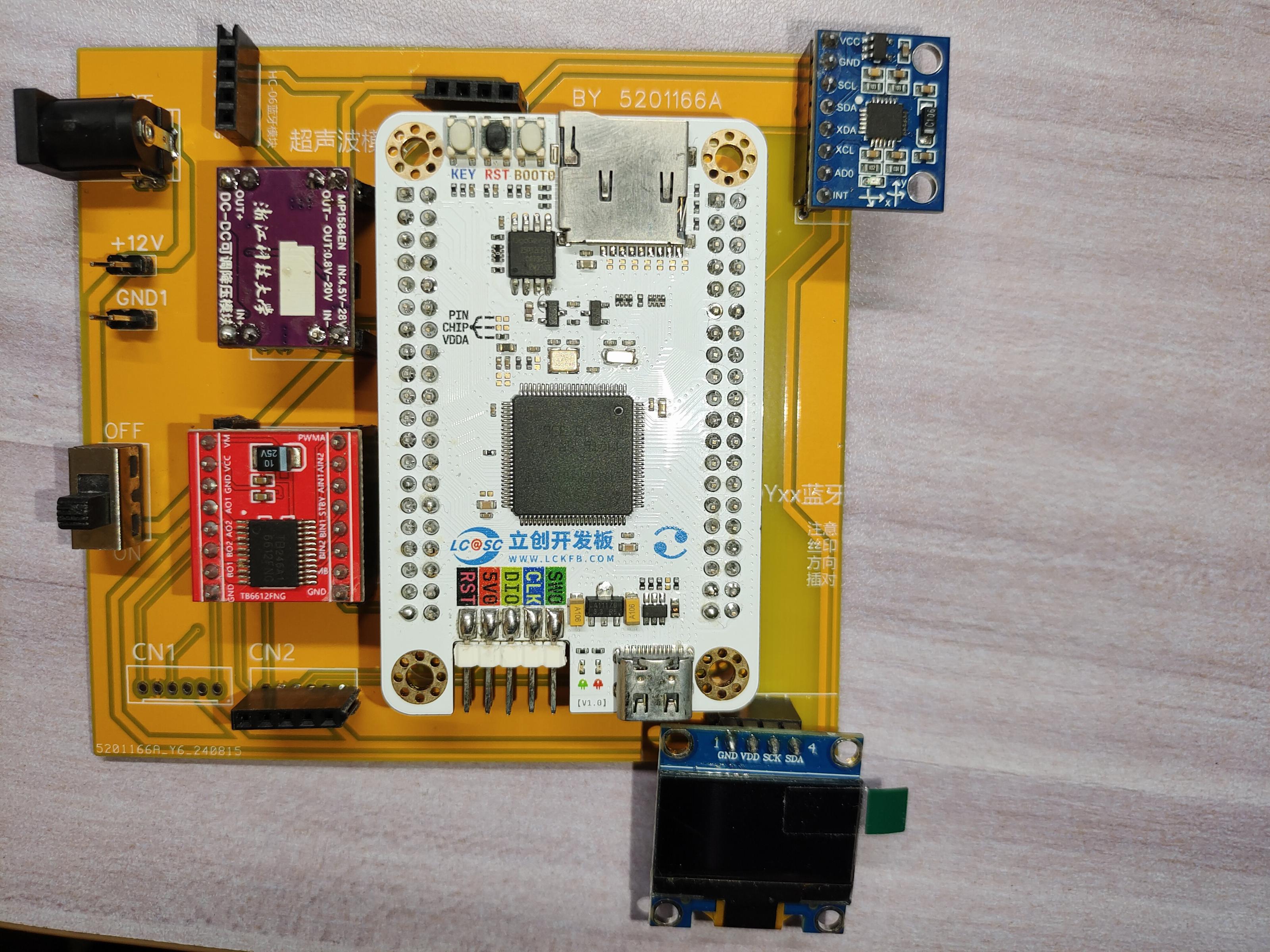
32f4 Car Control Learning Board
It retains OLED, gyroscope, motor drive, Bluetooth, and ultrasonic sensors.
It integrates commonly used modules such as OLED, gyroscope, motor driver, Bluetooth, and ultrasonic sensors. It can be used for learning, eliminating the need for a breadboard, and can also serve as the mainboard for a small car.
PDF_32f4 Car Control Learning Board.zip
Altium_32f4 Car Control Learning Board.zip
PADS_32f4 Car Control Learning Board.zip
BOM_32f4 Car Control Learning Board.xlsx
92310
STM32F407 Development Board
The STM32F407VET6 Multifunctional Extended Learning Board is a high-performance learning tool designed specifically for embedded system development. The following is a detailed description of this board:
I. Core Features
1. Processor and Performance
Processor: STM32F407VET6, based on the ARM Cortex-M4 core, with a main frequency of up to 168MHz and a performance of up to 210 DMIPS. It supports floating-point operations and DSP instructions, suitable for complex real-time control tasks.
Storage: Built-in 512 KB Flash and 192 + 4 KB SRAM, providing ample storage space for program and data storage.
2. Rich Peripheral Interfaces
Communication Interfaces: Includes 3 SPI interfaces, 3 USART interfaces, 2 UART interfaces, 2 I2S interfaces, 3 I2C interfaces, 1 FSMC interface, 1 SDIO interface, and 2 CAN interfaces, supporting multiple communication protocols for easy connection to various peripherals and sensors.
Other Peripherals: Equipped to meet the needs of different application scenarios.
II. Development Tools and Supported
Programming Environments Supports multiple development tools, such as Keil MDK, IAR Embedded Workbench, and ST's official STM32CubeIDE. These tools provide rich middleware libraries and sample code, helping users quickly get started and develop projects.
MicroPython Support: Some learning boards also support MicroPython programming, providing developers with the flexibility and ease of use of Python, lowering the learning threshold and improving development efficiency.
III. Application Scenarios
: IoT Device Development: Utilizing its rich communication interfaces and network support, the STM32F407VET6 multi-functional expansion learning board is suitable for developing various IoT devices, such as smart home devices and environmental monitoring systems.
Industrial Control: Its high-performance processor and multiple communication interfaces make it an ideal choice for industrial automation control, applicable to PLC control, motor drive control, and other scenarios.
Education and Research: As a teaching tool, it helps students and researchers quickly master embedded system development skills, promoting the development and application of embedded technology.
IV. Other Features
: Modular Design: Supports multiple expansion modules, such as the NRF24L01 wireless module, allowing users to easily expand functionality according to project needs.
Open Source: Based on open source protocols such as the MIT license, it encourages community contributions and secondary development, promoting technology sharing and progress.
Firmware Updates: Some boards support rapid firmware updates and deployment via DFU (Device Firmware Upgrade) mode, simplifying the development process.
The STM32F407VET6 multi-functional extended learning board is a powerful, flexible, and easy-to-use embedded system development learning tool suitable for various demanding application scenarios and project development needs.
PDF_STM32F407 development board.zip
Altium_STM32F407 development board.zip
PADS_STM32F407 development board.zip
BOM_STM32F407 Development Board.xlsx
92311
ESP32S3-SI4732 Receiver
This radio was built using an ESP32S3 microcontroller and an SI4732 DSP. The program is from https://github.com/ralphxavier/SI4735
First, I'd like to thank Xia, a member of the QQ group, for making the 3D printed and CNC shells. I revised them over ten times, and I kept bothering him.
1. The PCB thickness used is 1.6mm; other thicknesses cannot be used
. 2. The speaker uses a 1511 speaker: [Taobao] https://m.tb.cn/h.gOtbh6cJPcUydCH?tk=RhYT344WYoz HU9046 "1511/1609 Waterproof 8R 1W Aluminum Diaphragm Spring Square Magnet Speaker 8 Ohms 1 Watt Smartwatch Laptop Speaker"
3. The screen uses a 1.91-inch IPS: [Taobao] Limited-time Taobao Gold Coin discount of 0.1 yuan https://m.tb.cn/h.gmrmRjFVOkqiiRn?tk=wje1344eERm HU9046 "1.9-inch TFT Display 170*320 Dot Matrix ST7789 Driver 30Pin Plug-in Color Screen SPI Interface"
4. Encoder uses a 10mm high type: [Taobao] https://m.tb.cn/h.gOtYZbfqGps36AS?tk=uTyq344eHeT CZ0001 "EC11 10mm long Patch Rotary Encoder/Digital Potentiometer 5-pin with Switch"
5. Battery uses 603040,
800mAh 6. 3D printed housing screws, M2*14 self-tapping:

7. CNC housing screws: M2*16/M2*14:

8. Housing uses 3D printing or CNC machining, see attachment
9. Program source code is in the attachment. Currently, one problem encountered is that battery sampling is too frequent, causing the battery level to fluctuate constantly. The temporary solution is to reduce the number of battery levels to only 3, with 50% as one level. We appreciate the help of experts in optimizing
the Arduino development board configuration:
Board
ESP32S3 Dev Module/T-Display-S3
Port
COM x
USB CDC On Boot
Enable
CPU Frequency
240MHZ (WiFi)
Core Debug Level
None
USB DFU On Boot
Disable
Erase All Flash Before Sketch Upload
Disable
Events Run On
Core1
Flash Mode
QIO 80MHZ
Flash Size
16MB(128Mb)
Arduino Runs On
Core1
USB Firmware MSC On Boot
Disable
Partition Scheme
16M Flash(3M APP/9.9MB FATFS)
PSRAM
OPI PSRAM
Upload Mode
UART0/Hardware CDC
Upload Speed
921600
USB Mode
CDC and JTAG
3D Printed Shell.zip
ALL_IN_ONE_T-Display_S3.zip
libraries.zip
Approval approved + removal of speaker partition + potentiometer recess.zip
PDF_ESP32S3-SI4732 Receiver.zip
Altium_ESP32S3-SI4732 Receiver.zip
PADS_ESP32S3-SI4732 Receiver.zip
BOM_ESP32S3-SI4732Receiver.xlsx
92312
ESP32 MP3 music player
MP3 music player based on ESP32
Project Overview:
This project is an MP3 music player based on the ESP32 microcontroller, featuring music playback, time display, and TXT e-book reading capabilities.
Functionally,
it reads audio and image files from a TF card, controls power on/off with buttons, and uses a scroll wheel to switch pages.
Project Parameters and Principles
: Audio Section: The decoder used is the ES8311, whose performance is sufficient for decoding and is reasonably priced. The power amplifier chosen is the NS4150C, known for its excellent full-bandwidth EMI suppression and overcurrent/overvoltage protection.
Main Control Section: The main control uses the ESP32-WROOM, which has strong processing capabilities and supports Bluetooth and Wi-Fi connectivity, facilitating the transfer of small files.
Screen Section: A 2.13-inch monochrome e-ink screen is used; note that it has 24 pins with a 0.5mm pitch.
Power Supply Section: An LTH7R battery management chip is used, supporting a maximum charging current of 500mA, sufficient for charging the built-in lithium battery.
Software Code
: The code is based on the e-ink MP3 code from the Bilibili blogger "甘草酸不酸". The link is as follows:
https://www.bilibili.com/video/BV1vN411H7im/?spm_id_from=333.999.0.0&vd_source=20de9517a9b4fb7a9f4340b8872aa64e
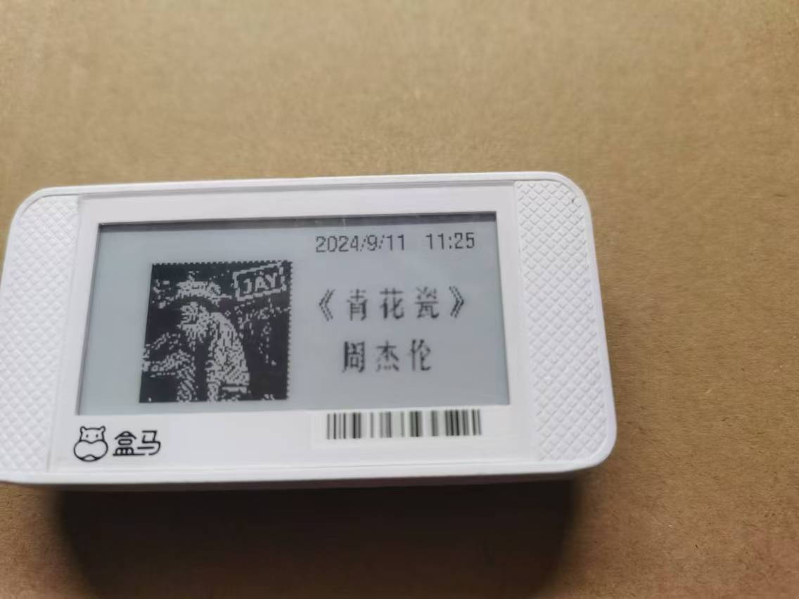
(Image of the actual product)
PDF_ESP32 MP3 Music Player.zip
Altium_ESP32 MP3 Music Player.zip
PADS_ESP32 MP3 Music Player.zip
BOM_ESP32 MP3 Music Player.xlsx
92313
4-channel power output module (with negative voltage output)
This module is based on the LM2596 series to obtain 12V, 5V, and 3.3V, and the TPS5430 to obtain -12V.
Chip Introduction:
LM2596 Series
. The LM2596 is a fixed-frequency switching power supply regulator with the following features:
Input voltage range: 4.5V to 40V;
Adjustable output voltage (via external resistor divider);
Multiple output versions available;
Output current: Up to 3A;
High efficiency: Up to 90% or more;
Built-in over-temperature and short-circuit protection .
TPS5430.
The TPS5430 is a high-efficiency buck converter with the following features:
Input voltage range: 4.5V to 40V;
Output current: 3A;
Programmable switching frequency;
Built-in soft-start, over-temperature protection, and short-circuit protection. LM2596 Series Circuit Design
: 12V Output: Using the LM2596S-12 chip, the voltage is 12V. 5V Output: Using the LM2596S-5 chip, the output voltage is 5V. 3.3V Output: Using the LM2596-3.3 chip, the output voltage is 3.3V. TPS5430 Circuit Design -12V Output: Using the TPS5430 chip, the output voltage is set to -12V via an external feedback resistor network. Protection circuit includes a fuse and a diode to prevent reverse polarity . Input voltage: 12V-36V (LM2596-12 will not function properly below 12V). The module shown in the diagram has two chip pins that are not grounded; this error has been corrected in the current project. 12V input, 3.3V output ; 12V input, 5V output ; 12V input, 12V output; 12V input, -12V output.


PDF_4-channel power output module (with negative voltage output).zip
Altium 4-channel power output module (with negative voltage output).zip
PADS 4-channel power output module (with negative voltage output).zip
BOM_4-channel power output module (with negative voltage output).xlsx
92314
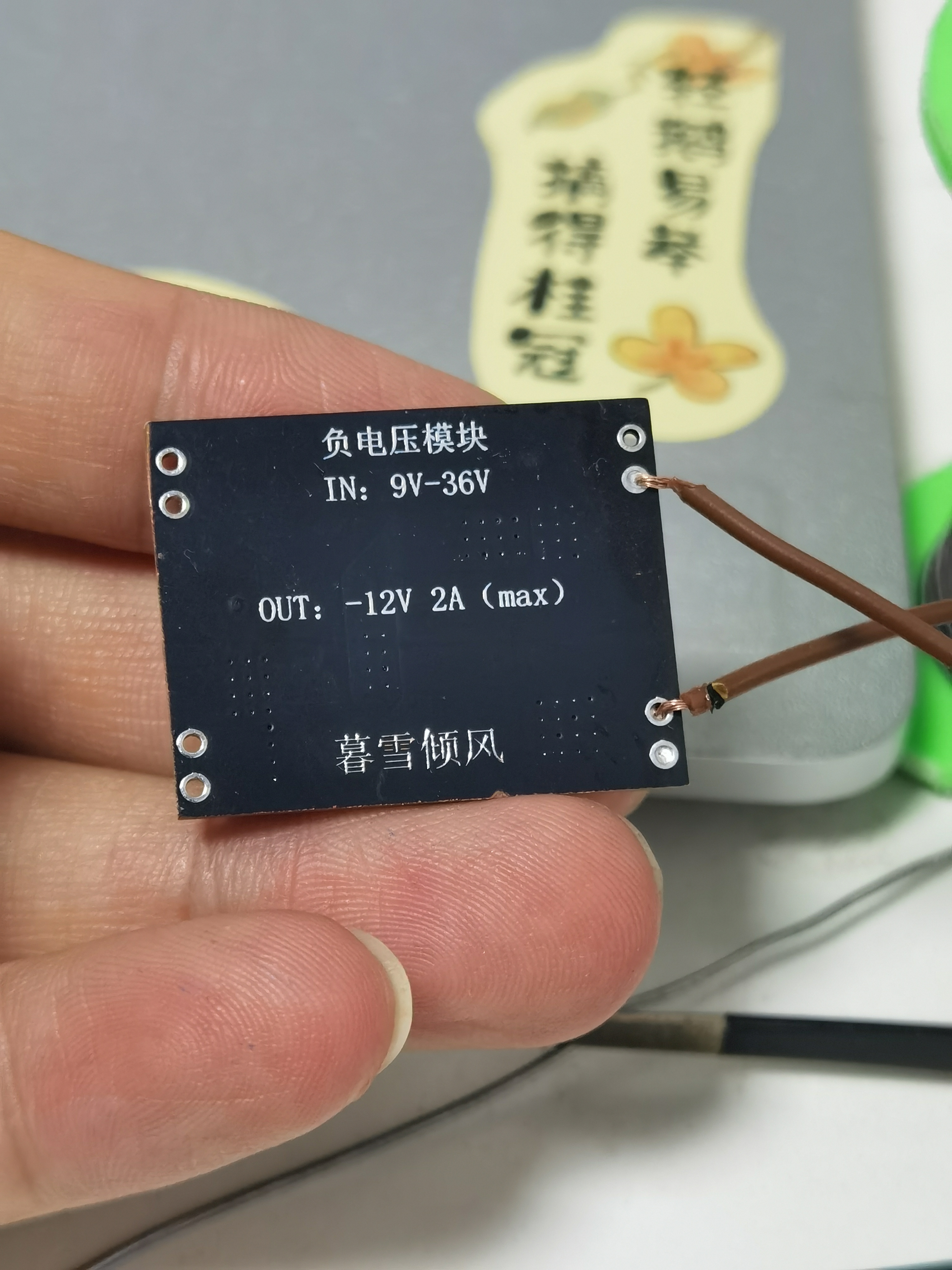
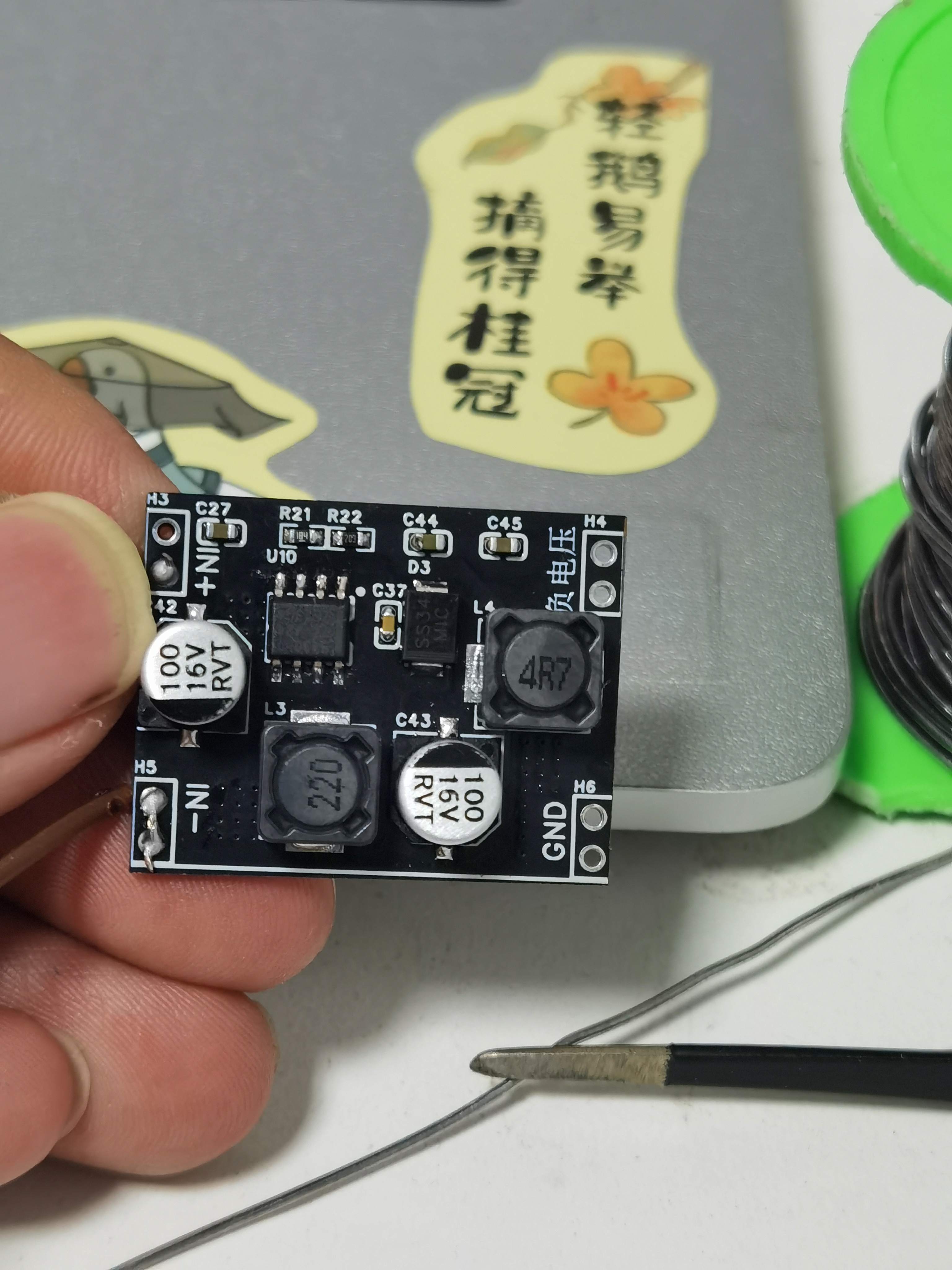
TPS5430 Negative Voltage Module -12V
This open-source project aims to design and implement a negative voltage module based on the TPS5430 chip, suitable for electronic systems and circuit designs requiring negative power supplies. The TPS5430 is a high-performance switching power supply chip that provides efficient and stable power solutions.
The TPS5430 is a buck converter with the following features:
Input voltage range: 4.5V to 40V;
Output current: 3A;
High efficiency: up to 95%;
Programmable switching frequency: 100kHz to 1MHz;
Built-in soft-start function;
Over-temperature protection and short-circuit protection
; Small package for easy PCB layout;
Input voltage: 9V-36V;
Output voltage: -12V

PDF_TPS5430 Negative Voltage Module -12V.zip
Altium_TPS5430 Negative Voltage Module -12V.zip
PADS_TPS5430 Negative Voltage Module -12V.zip
BOM_TPS5430 Negative Voltage Module -12V.xlsx
92315
electronic


 京公网安备 11010802033920号

 BF568
BF568


