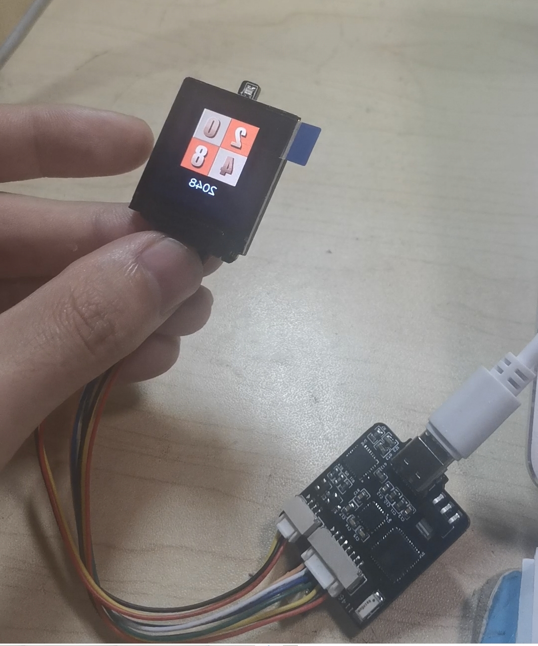
This device, based on the ESP32-pico-d4, functions as a small TV, serving as a desktop terminal and decorative item, displaying information such as time and weather. Additionally, due to the gyroscope on the board, it can also play games like 2048. Due to size restrictions, the full image cannot be displayed here; a full image is provided instead.
1. Project Description:
a. Create a desktop clock that displays time and temperature.
b. Include IoT buttons to control computer power-on and indoor lighting.
c. Upload temperature and humidity data to Home Assistant to control home temperature (operate air conditioner and humidifier).
Schematic Diagram Explanation:
a. Main control chip uses ESP32-C3, employing a ceramic antenna.
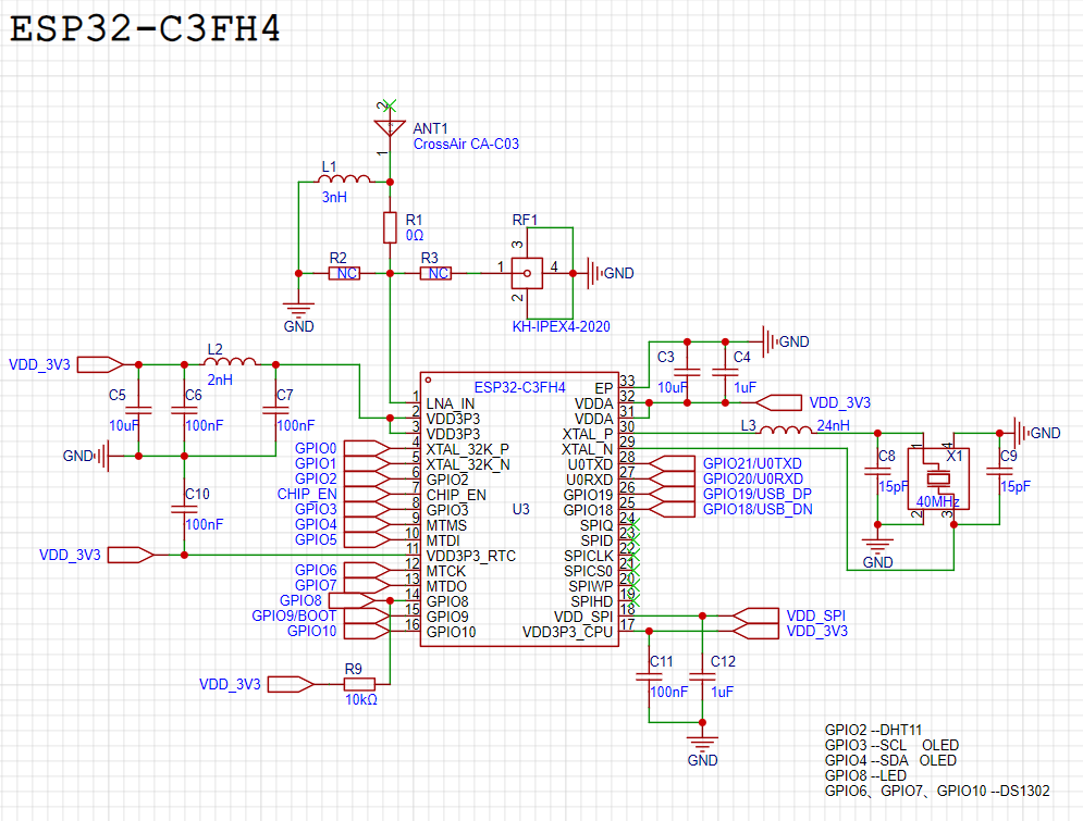
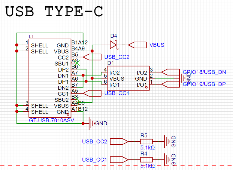
b. Type-C power supply and data programming.
c. 6211 LDO 5V to 3.3V power supply.

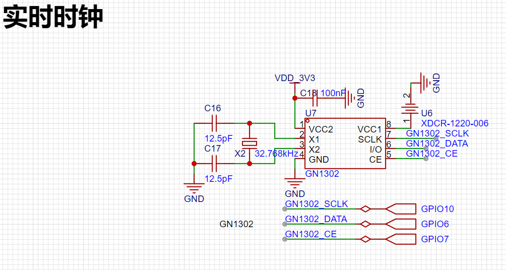
d. Real-time clock uses DS1302.
e. The temperature and humidity sensor uses a DHT11

display, with two
options: a 3.2-inch OLED and

a digital-to-analog tube (DAC). The

latter is currently being tested. The battery uses a single 18650 cell, a TP5400 charge/discharge regulator chip, and an IP3005A battery protection chip.

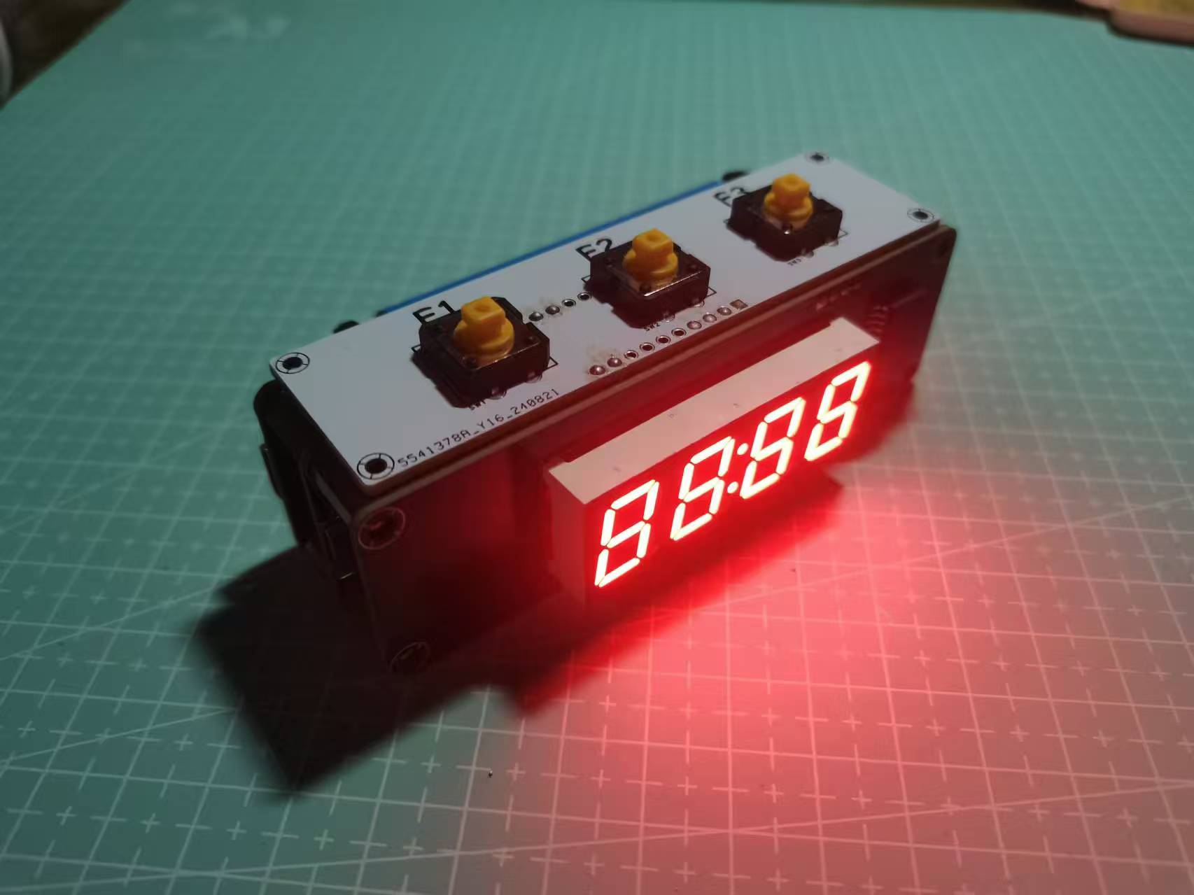
The structure consists of
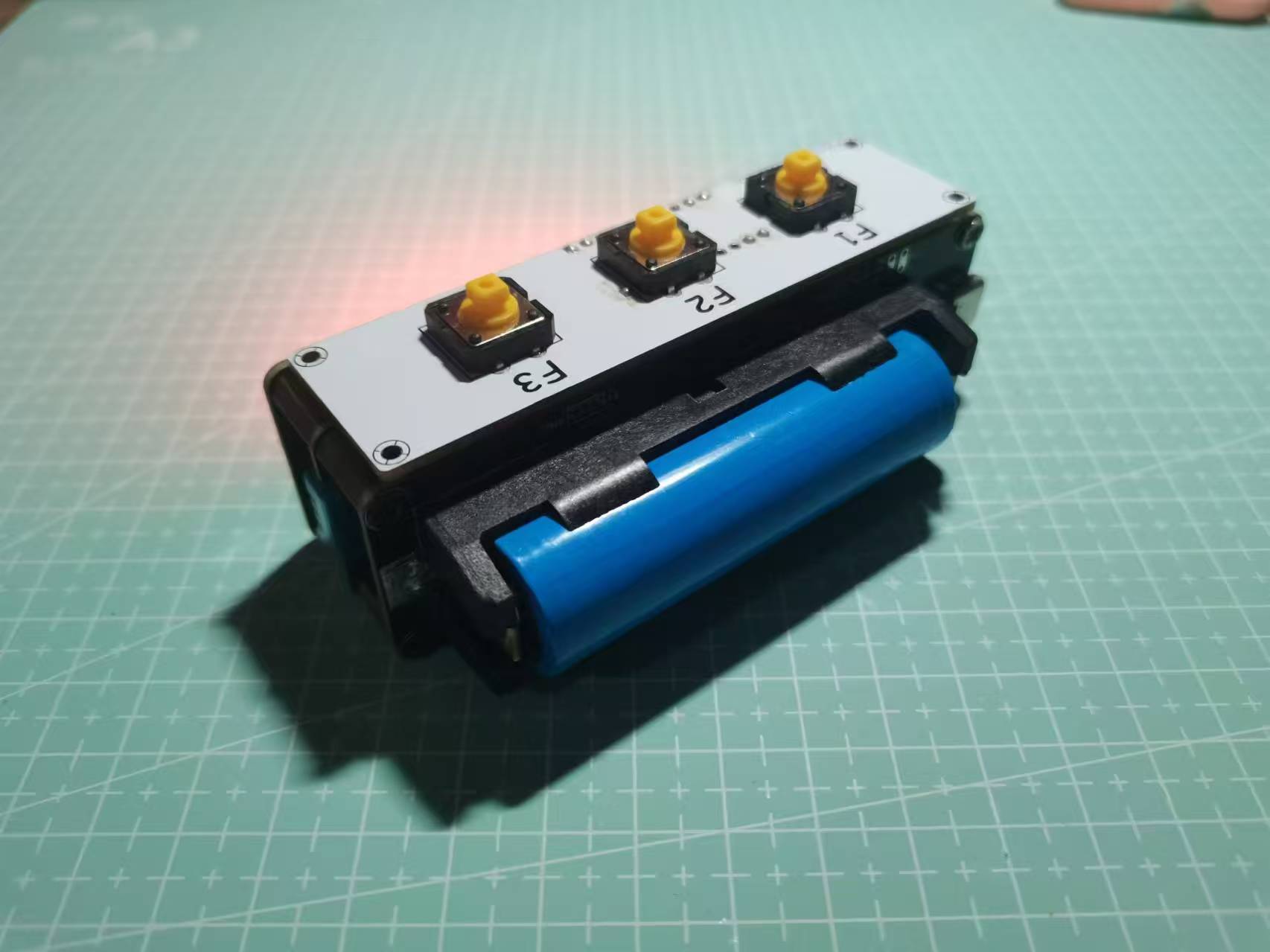
four boards: a core board, a battery board, a display board, and a button board. The core board, battery board, and display board are connected by 11mm copper pillars, and the button board is connected by bent female connectors. The connection is quite secure, with no looseness. The
following image shows the actual product, and the effect is acceptable. It looks a bit like a C4 chip, haha.
PDF_ESP32 Multifunctional Temperature and Humidity Clock.zip
Altium_ESP32 Multifunctional Temperature and Humidity Clock.zip
PADS_ESP32 Multifunctional Temperature and Humidity Clock.zip
BOM_ESP32 Multifunctional Temperature and Humidity Clock.xlsx
92343
Learning extension based on SkyStar STM32F407VET6
Based on the LCSC Skystar STM32F407VET6 learning expansion board
This expansion board is based on the Skystar STM32F407VET6 and consists of an OLED display, a digital tube, an NRF24L01 and TB6612FNG motor driver chip, buttons, etc. It is convenient for beginners to learn about IIC, SPI, timers, external interrupts, and other related knowledge. It also includes motor drivers and supports the use of I2C motors and ordinary motors. All pins on the development board are brought out, providing convenience for subsequent learning of other peripherals.
IMG_20240909_215151.jpg
STM32F407VET6 expansion board pinout.txt
STM32F407VET6 Expansion Board Applications.zip
PDF_Extended Learning Version Based on SkyStar STM32F407VET6.zip
Altium_Learning Extension Version Based on SkyStar STM32F407VET6.zip
PADS_Learning Extension Edition Based on SkyStar STM32F407VET6.zip
BOM_Based on Skystar STM32F407VET6 Learning Extension.xlsx
92345
ESP32-based smartwatch verification board
The smartwatch verification board, designed based on the chappie2 open-source project,
is equipped with a microphone, barometer, posture sensor, RTC clock,
and USB support for switching between ESP-USB and USB-to-serial ports.
The project has been verified. The overall design is based on https://oshwhub.com/eedadada/chappie2 . The USB switching circuit has been modified to support switching the USB-C function via a switch. The onboard USB to serial port facilitates debugging.
This is my first time designing a board. Compared to the reference project, it has reduced the difficulty to a certain extent. After this board is successfully verified, we will consider the subsequent improvement plan . [ ] Change the power management to AXP2101 [ ] Add a vibration motor [ ] Modify the board shape and circuit to make it more suitable for watches [ ] Add a MAX30102 heart rate sensor. The software is based on ESP-IDF. Developed using v5.3, code details can be found at https://gitee.com/liu-lejian/kotone-watch. The sensor I2C driver is based on the new i2c_master.h header file of ESP-IDF and does not support older versions of the ESP-IDF i2c.h header file. The USB switching circuit can switch between ESP-USB and UART-USB, but hot-switching is not supported; the Type-C port needs to be unplugged and plugged back in for the switch to take effect. It uses many surface-mount components; replication is not recommended without a heating platform/hot air gun.
PDF_ESP32-based Smartwatch Verification Board.zip
Altium_ESP32-based Smartwatch Verification Board.zip
PADS_ESP32-based Smartwatch Verification Board.zip
BOM_ESP32-based Smartwatch Verification Board.xlsx
92346
ECGEV
Heart rate card, collects ECG waveforms, LED simulates an ECG to indicate heart rate, and supports sending ECG waveforms via Bluetooth.
AFE: AD8232
MCU: STM32WB55

ecgev.mp4
ECGW.zip
PDF_ECGEV.zip
Altium_ECGEV.zip
PADS_ECGEV.zip
BOM_ECGEV.xlsx
92348
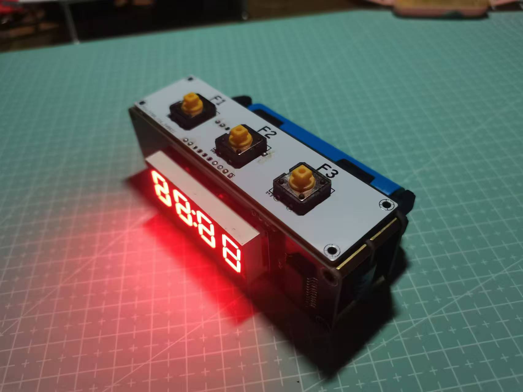
Desktop mini weather clock
This project uses Espressif's ESP8266 as the main controller to drive a 1.54-inch TFT LCD screen, and employs capacitive touch buttons, WS2812 LEDs, and a buzzer to create a popular WiFi weather clock desktop decoration. In addition to the standard weather clock functionality, this project also includes a photo album feature.
This project uses Espressif's ESP8266 as the main controller; please ensure you purchase the correct model


to drive a 1.54-inch TFT LCD screen.

It utilizes capacitive touch buttons, WS2812 LED lights, and a buzzer to create a popular WiFi weather clock desktop decoration.

In addition to the standard weather clock functionality, this project adds a photo album feature, allowing for one-click upload and deletion via a mini-program or webpage, further enhancing its practicality. Capacitive touch buttons are also added for switching interfaces, increasing ease of use and interactivity.
The addition of WS2812 LED lights adds a cool effect to the small TV, offering various ambient lighting effects: fixed color; fixed color breathing light; and fixed brightness gradient color. A buzzer is added to function as an alarm clock, a long-awaited and practical feature. It supports setting up to three alarms, each with options for: single alarm, weekday, and daily alarms, sufficient for daily use.
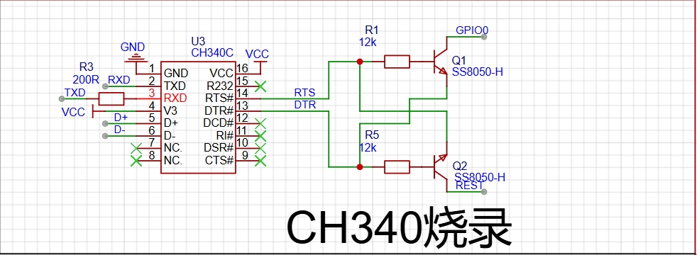
The CH340 chip is used for programming.


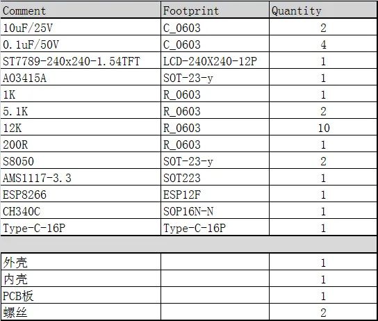
The following is the bill of materials.

3D Shell.rar
Gerber_Open Source ESP8266 Weather Clock WiFi Mini TV GIF Animation Custom Upload_2024-05-15.zip
PDF_Desktop Mini Weather Clock.zip
Altium Desktop Mini Weather Clock.zip
PADS_Desktop Mini Weather Clock.zip
BOM_Desktop Mini Weather Clock.xlsx
92349
ESP32 WiFi temperature and humidity ornament
A desktop ornament for temperature and humidity control that connects to WiFi using ESP32-C6.
The main control chip is ESP32-C6-MINI, used to connect to WiFi and obtain current weather and temperature changes. Before use, you need to pre-set the WiFi name (preferably without spaces, otherwise it won't connect), WiFi password, and location to obtain the current temperature and time.
The built-in AHT20 sensor detects the ambient temperature and humidity, providing a more accurate representation of perceived temperature and humidity.
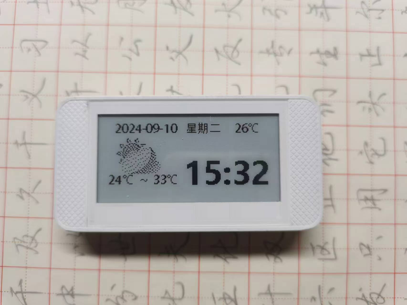
The display uses an e-ink screen with a simple interface and low power consumption. Icons are sourced from the internet; the image is shown below.

The charging section uses a TP4056 charging/discharging chip to meet charging needs; the battery can be selected according to your requirements.
The casing can be designed to match the size of the e-ink screen price tag. The overall effect is shown below:
PDF_ESP32 WiFi Temperature and Humidity Ornament.zip
Altium_ESP32 WiFi Temperature and Humidity Ornament.zip
PADS_ESP32 WiFi Temperature and Humidity Ornament.zip
BOM_ESP32 WiFi Temperature and Humidity Ornament.xlsx
92350
electronic
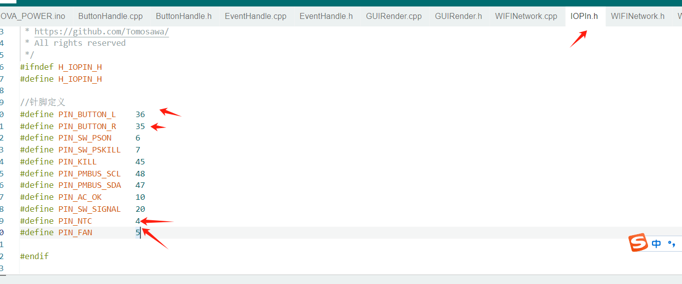 2. Simultaneous pressing of two buttons controls fan startup
  button
  3. Board temperature control function
  section and locate the "Add Partition Configuration File" section.
  Add the following code below it:
  tips
tips 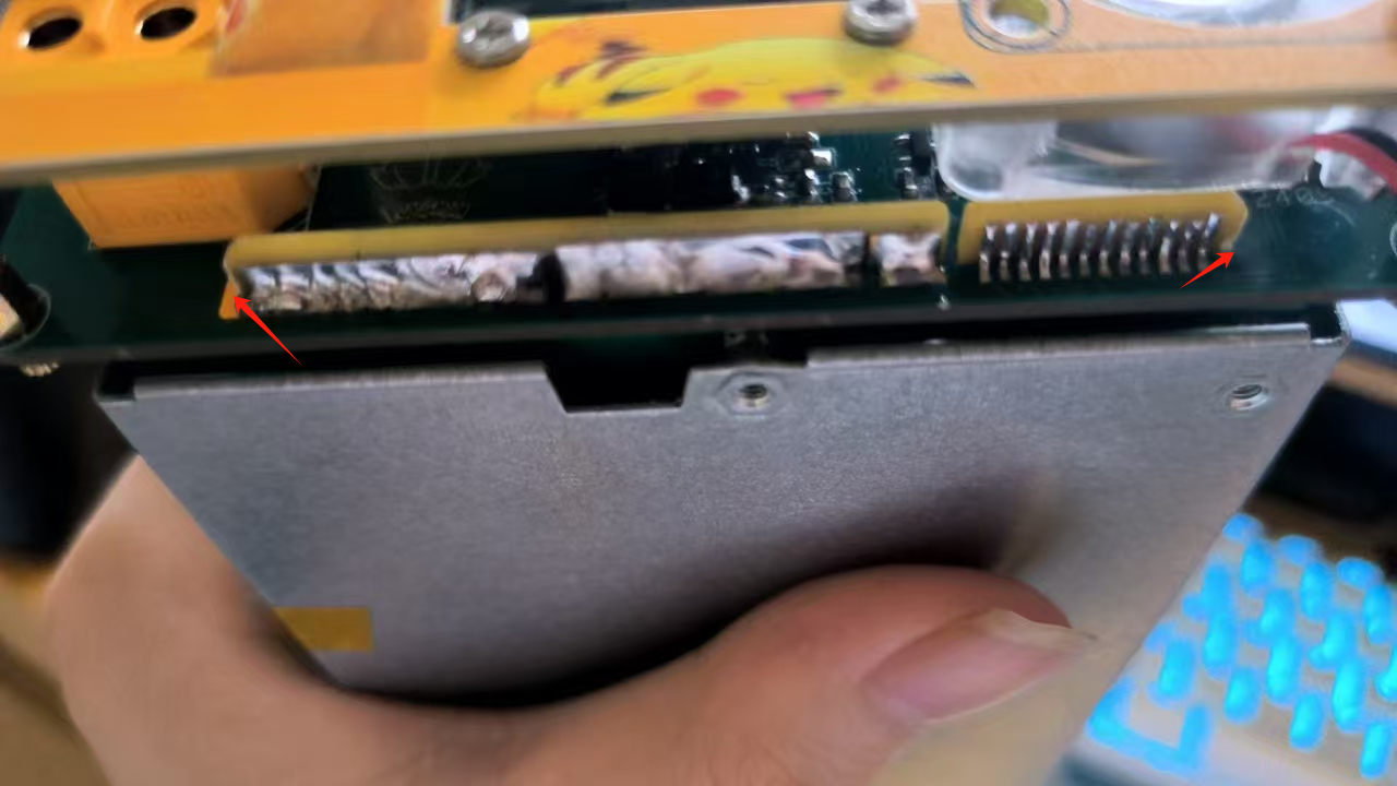


 京公网安备 11010802033920号

 TC1303B-BN1EMFTR


