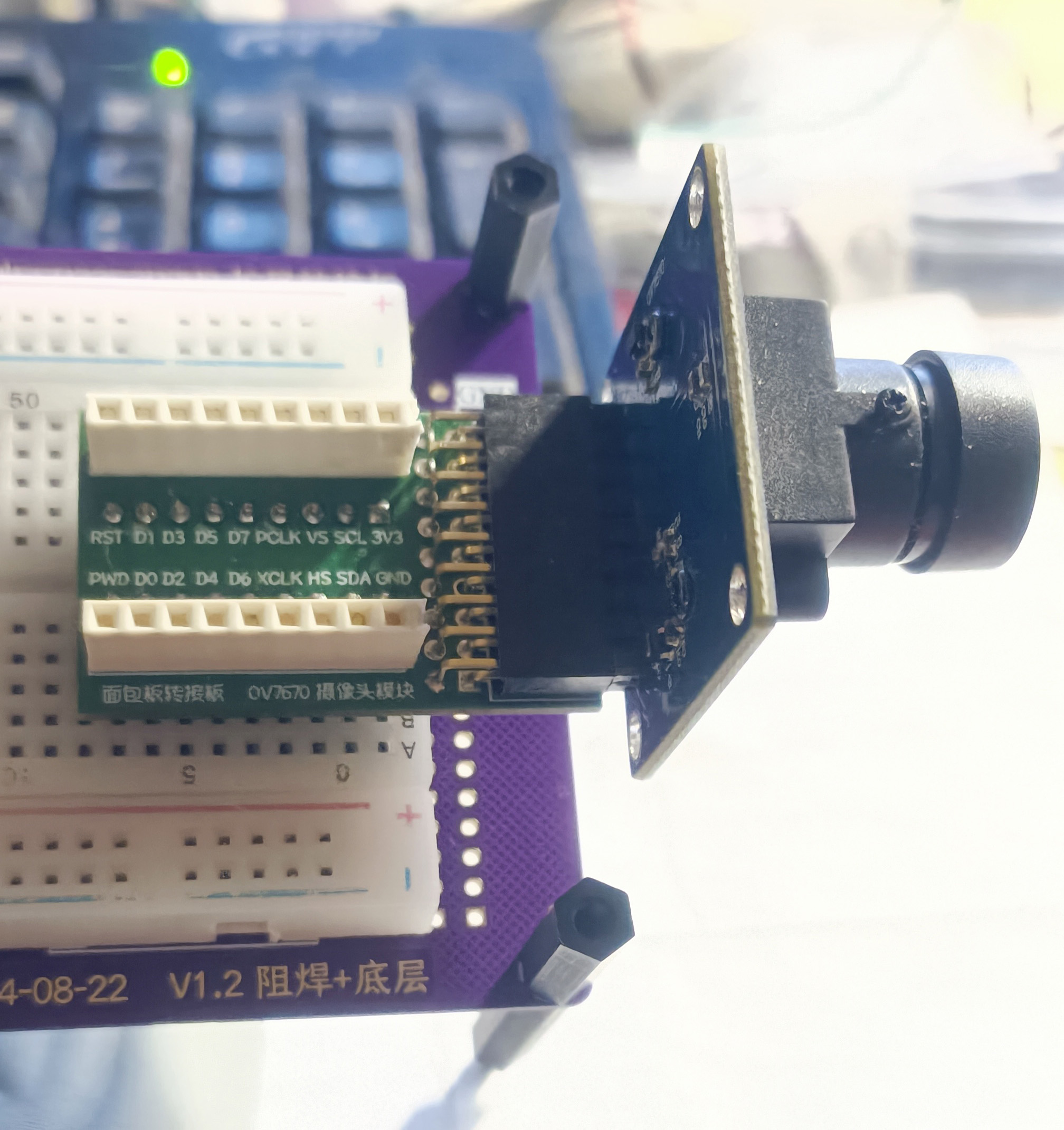
Because this camera has so many control cables, this adapter board was designed purely for easy debugging of the camera on a breadboard, and it works very well. The bottom layer has pins that directly plug into the breadboard, while the top layer has expansion ports. Since the space on the breadboard is very small, additional top-side connectors were designed for easier debugging. The plug on the right is for connecting the OV7670 camera.
Due to limited space, there are a lot of ribbon cables—a whopping 18! The design uses a 4-layer board.
Learning to design and build a digital voltmeter and ammeter is highly beneficial for enhancing one's professional skills. The digital voltmeter and ammeter project encompasses multiple aspects, including the design and implementation of microcontroller circuits, the design of signal acquisition and processing circuits, the development and optimization of the user interface, and the design of the product's appearance.
1. Hardware Section 1.1 The power supply circuit
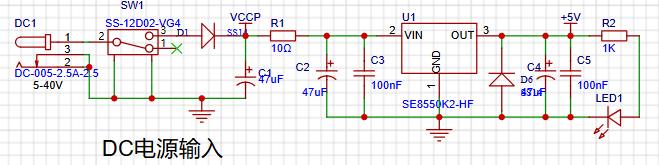
adds D5, a parallel reverse diode, to prevent short circuits in the subsequent stages from damaging the SE8550K2.
1.2 Serial Communication
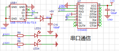
An onboard CH340 chip is added for serial communication.
1.3 INA226 Test Circuit

2. MCU Selection
The project uses the LCSC CW32F030C8Tx development board (core board) as the main controller. The selection of the controller is crucial, as it relates to the overall project performance.
Regarding the voltage and current meters, the author conducted some debugging and testing using STM32/CW32 and some other 32-bit microcontrollers. Here, only a comparison with the STM32F103C8T6 is made as a reference for learning device selection, mainly to provide ideas and improve understanding.
Avoid Blind Selection When selecting the MCU (microcontroller unit) for this project, multiple aspects need to be considered to ensure that the selected MCU meets the project requirements.
Clearly define your project requirements: Clearly understand how much computing power the project needs, including clock speed, processor core type, and whether a floating-point unit is required.
Clearly define the required I/O ports and important peripherals for the project, such as the ADC peripheral. Since this is a development board project, the main purpose is debugging and learning; therefore, there are no strict limitations on the number of I/O ports, i.e., cost issues are not considered.
The key advantages of CW32 in this project include
: wide operating temperature range (-40~105℃)
, wide operating voltage range (1.65V~5.5V, STM32 only supports 3.3V systems)
, strong anti-interference capability (HBM ESD 8KV), and ESD reliability reaching the highest international standard level (STM32 ESD 2KV).
The focus of this project is a better ADC: a 12-bit high-speed ADC achieving ±1.0LSB INL 11.3ENOB, multiple Vref reference voltages... (STM32 only supports VDD=Vref), and
stable and reliable eFLASH technology.
A detailed explanation of these advantages will be provided in the chapters on ADC sampling and related extensions.
The main characteristics of the CW32 ADC need to be focused on in this project. The content is from the "CW32x030 User Manual".

3. Difficulties encountered and solutions during debugging:
1. Poor soldering skills + inadequate soldering tools resulted in the soldering of some important and usable components.
2. The LDO overheated upon power-up, and the power indicator light did not illuminate. Initially, it was thought to be a short circuit, and even a resoldering of the LDO was performed before it was discovered that the parallel reverse diode of the LDO was soldered backwards.
3. During ADC sampling, the sampled value is full value, and adjusting the potentiometer has no effect. A multimeter shows the voltage at the ADC sampling point is consistently 4.1V, but the voltage input from the potentiometer is lower than 4.1V. Inspection revealed that the voltage is clamped.
4. Demonstration video:
https://www.bilibili.com/video/BV1DcH1exEar/?spm_id_from=333.999.0.0&vd_source=e431ef29bac3cec707d741e5705ef7a2
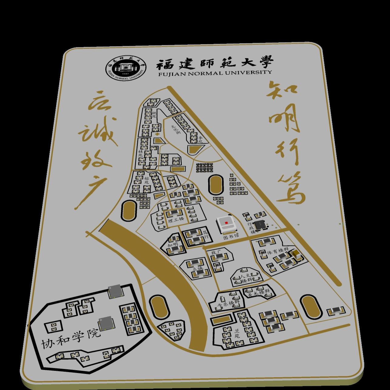
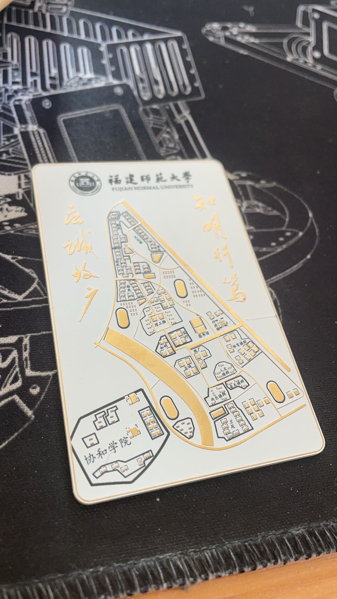
Fujian Normal University Campus Computer Association NFC Card Color Silk Screen Printing
Project Overview:
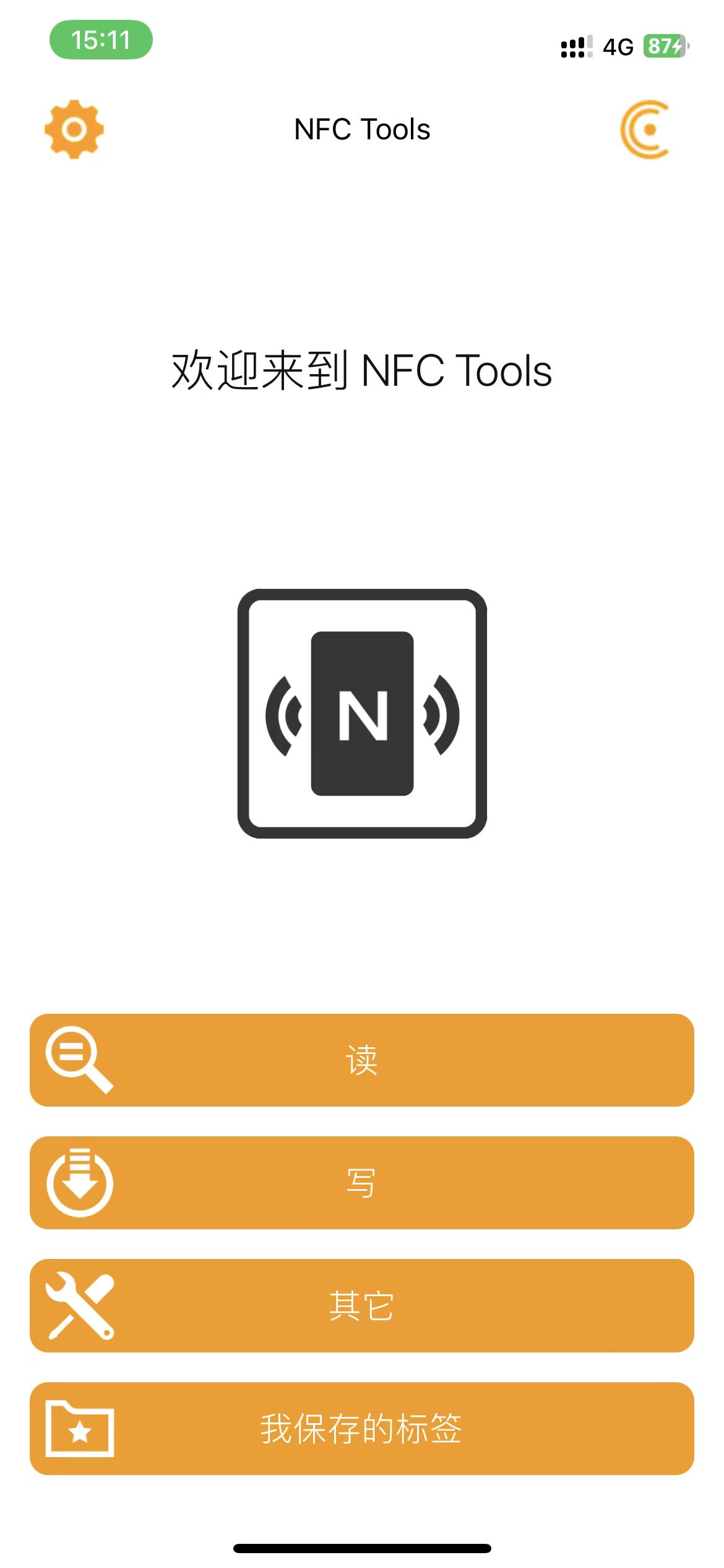
This project is a color-screened campus NFC map. The NFC chip used is NT3H1101W0FHKH.
The project's functionality
includes allowing users to directly write NFC data via a mobile app; the RGB LEDs will flash during scanning.
PDF_Fujian Normal University Campus Map NFC Card.zip
Altium_Fujian Normal University Campus Map NFC Card.zip
PADS_Fujian Normal University Campus Map NFC Card.zip
BOM_Fujian Normal University Campus Map NFC Card.xlsx
92514
TKeyboard87_v3
Keyboard PCB based on ESP32
Video Link:
Bilibili Video -- Self-taught Keyboard Recording:
A Keyboard PCB Based on ESP32.
It uses SPI combined with a shift register to scan key states and includes an automatic USB download circuit.
PDF_TKeyboard87_v3.zip
Altium_TKeyboard87_v3.zip
PADS_TKeyboard87_v3.zip
PDF_TKeyboard87_v3.zip
Altium_TKeyboard87_v3.zip
PADS_TKeyboard87_v3.zip
BOM_TKeyboard87_v3.xlsx
92515
Allwinner H3 base plate
The Realtek Allwinner H3 core board, priced at 19.9 RMB on Xianyu (a second-hand marketplace), only exposes basic interfaces.
This is a Ruijie Vision H3 core board, suitable for sale on Xianyu (a second-hand marketplace) for 19.9 RMB. It features a 100M Ethernet port, a TF card slot, and uses a DC5525 power supply.
[Images: ![IMG_20240901_160131.jpg]
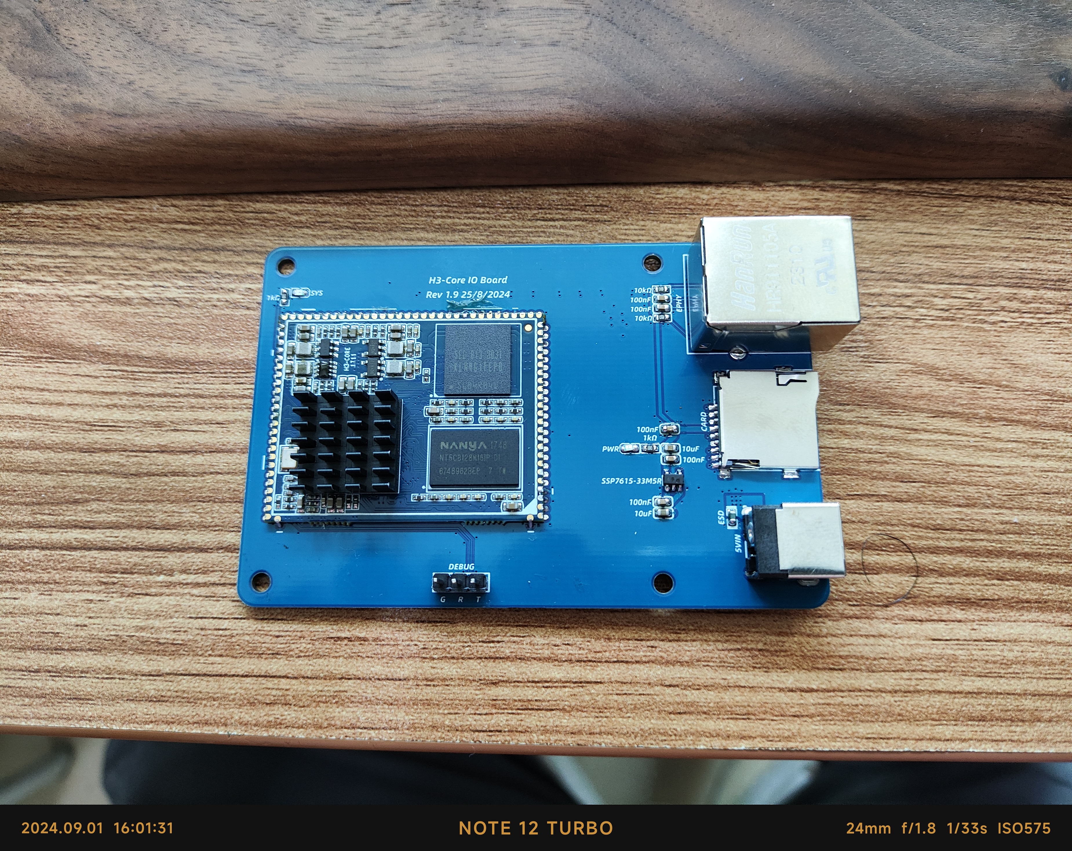
![IMG_20240901_160745.jpg]
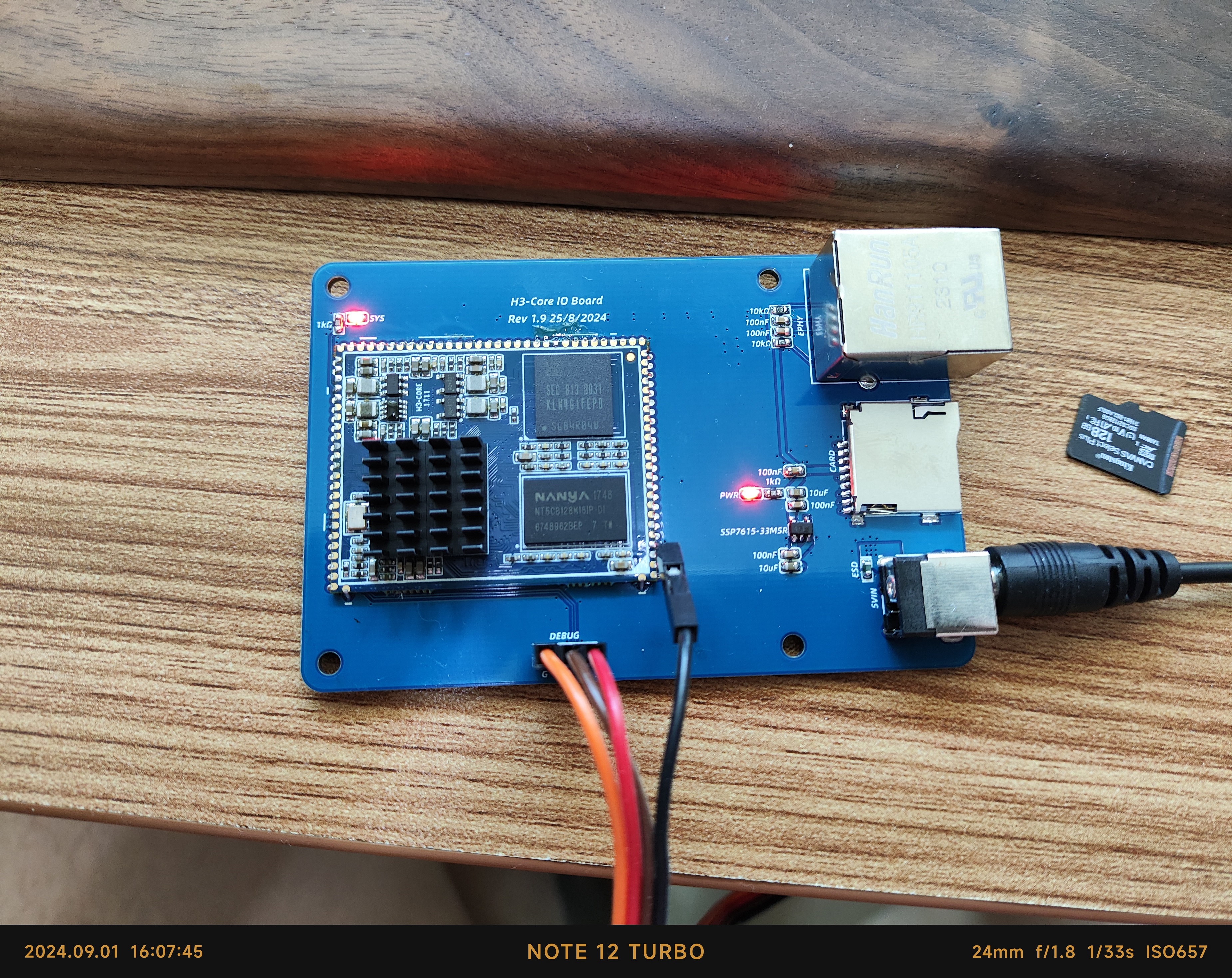
![1725178131070.png]]

PDF_Allwinner H3 Baseplate.zip
Altium_Allwinner H3 baseplate.zip
PADS_Allwinner H3 baseplate.zip
BOM_Allwinner H3 Base Plate.xlsx
92516
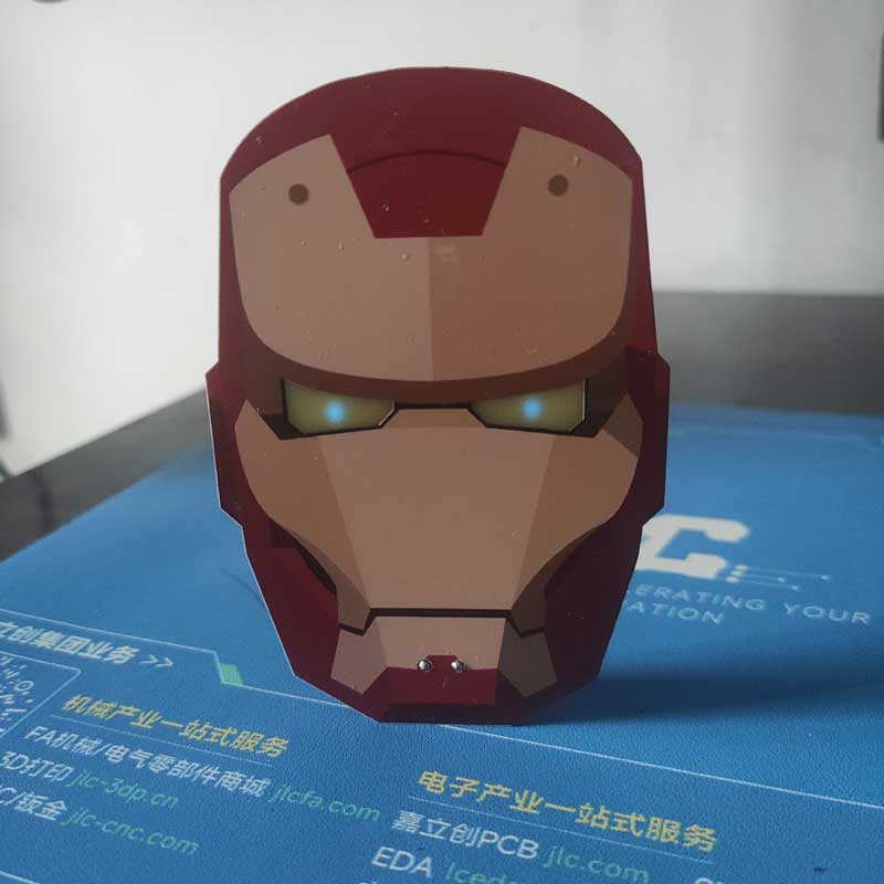
The Unquenchable Light of Civilization - Iron Man Eternal Light Figurine
This is a modified version of the Civilization of Light by the master of Negative Entropy Light. The main components are solar panels, LEDs, and supercapacitors; it charges when there is light during the day and lights up when there is no light at night!
This is a modified version of the "Light of Civilization" project by the master "Light of Negative Entropy," primarily consisting of solar panels, LEDs, and supercapacitors. It charges during the day with sunlight and lights up at night when there is no light!
Respect to the master: https://oshwhub.com/FJ956391150/yong-heng-zhi-guang


VID_20240828_160604.mp4
PDF_The Unquenchable Light of Civilization - Iron Man Eternal Light Ornament.zip
Altium - The Unquenchable Light of Civilization - Iron Man Eternal Light Figurine.zip
PADS_The Unquenchable Light of Civilization - Iron Man Eternal Light Figurine.zip
BOM_The Unquenchable Light of Civilization - Iron Man Eternal Light Ornament.xlsx
92518
electronic
 of the actual product)
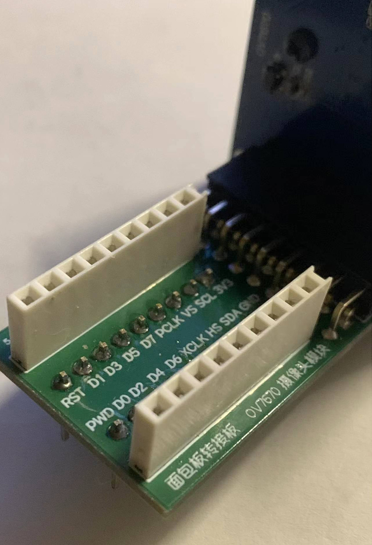


 京公网安备 11010802033920号

 177-714-2-37GP4J1-24PCG


