
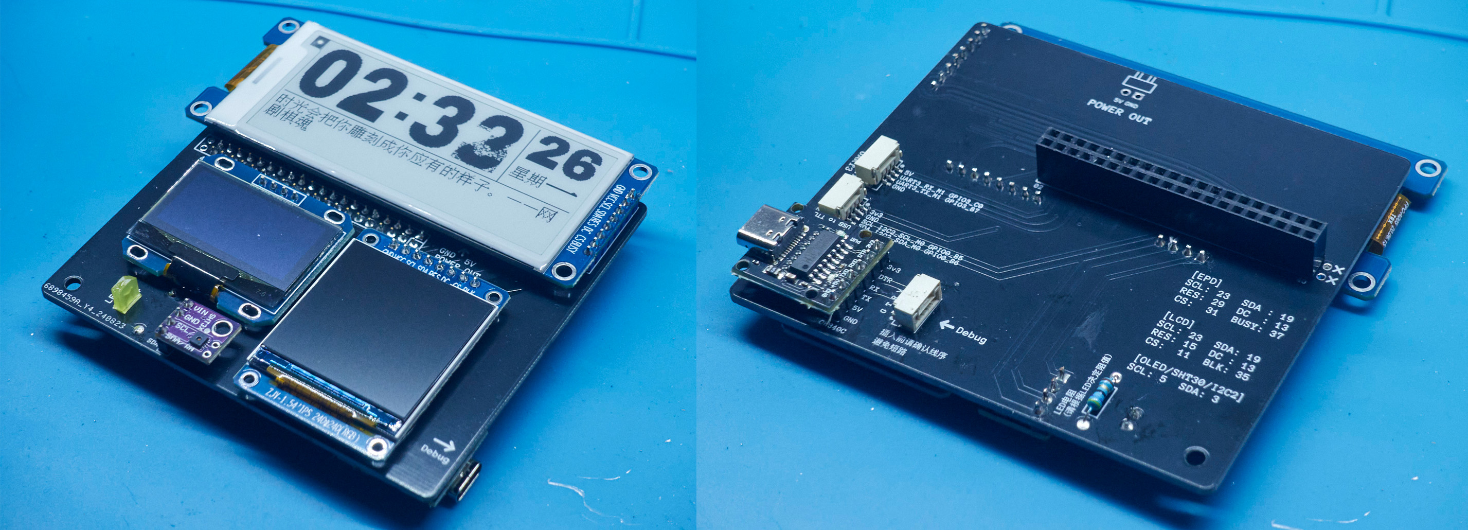
This 40-pin expansion board with three screens can be used for development and learning, or, when paired with a casing, transforms the Taishanpai into a mini desktop computer, allowing users to customize the screen display content.
Key features include
: a 2.9-inch monochrome e-ink screen module (128*296, driver: SSD1680)
from Zhongjingyuan; a 1.54-inch TFT display module (240*240, driver: ST7789) from Zhongjingyuan;
a 0.96-inch OLED module (128*64, driver: SSD1306)
; a CH340C module for easy serial port debugging;
an LED indicator light; and
an SHT30 temperature and humidity module
casing. The
casing uses 3D printing and a custom panel from JLCPCB, which covers the front and can be replaced with a 3D printed panel.
The Taishanpai is secured to the casing with four 10mm high copper pillars, and the expansion board is then plugged into the 40-pin interface.
On the left side, there's a hole for the button, making it easy to press.
On the right side, there are holes for Debug, serial port, and I2C output (the Type-C port for Debug is small and difficult to connect; the model could be modified to enlarge the hole)
. The lower left corner can be glued with hot glue to the power module included with the Taishanpai; there's an opening at the back for power supply from the rear.
The top has holes for the Taishanpai interface, as well as a circular antenna hole for extending the antenna or inserting an SMA interface antenna.

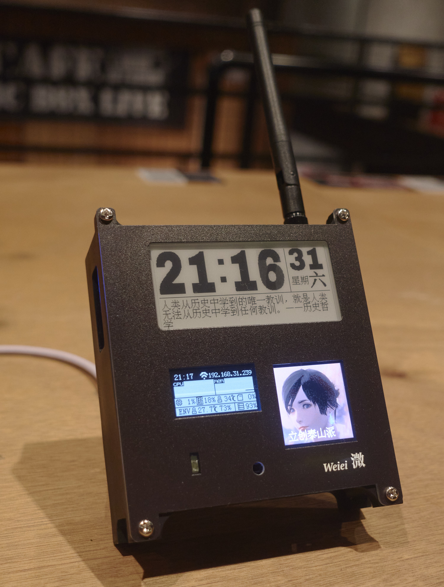
(Powered by JLCPCB panel + gain antenna + PD power module)
Driver Tutorial
1. Modifying the Device Tree
The Taishanpai uses the official Ubuntu image; the system was flashed directly according to the official tutorial.
Because the e-ink screen and LCD screen use SPI communication, while the OLED uses I2C communication, the official system image's device tree doesn't have SPI settings; it needs to be manually modified, and then the core recompiled. This part can be referred to the device tree section of the official tutorial.
First, follow the official tutorial to create an Ubuntu virtual image and download the system SDK. Then, modify the tspi-rk3566-user-v10-linux.dts file located in kernel/arch/arm64/boot/dts/rockchip.
Add a spi3.0 device
spi3: spi@fe640000 {
compatible = "rockchip,rk3066-spi";
reg = <0x0 0xfe640000 0x0 0x1000>;
interrupts = ;
#address-cells = <1>;
#size-cells = <0>;
clocks = <&cru CLK_SPI3>, <&cru PCLK_SPI3>;
clock-names = "spiclk", "apb_pclk";
dmas = <&dmac0 26>, <&dmac0 27>;
dma-names = "tx", "rx";
pinctrl-names = "default", "high_speed";
pinctrl-0 = <&spi3m0_cs0 &spi3m0_cs1 &spi3m0_pins>;
pinctrl-1 = <&spi3m0_cs0 &spi3m0_cs1 &spi3m0_pins_hs>;
status = "disabled";
};
Set status
&spi3{
status = "okay";
pinctrl-names = "default", "high_speed";
// Enable SPI3, specify the pinctrl node and CS chip select pin
pinctrl-0 = <&spi3m1_cs0 &spi3m1_pins>;
pinctrl-1 = <&spi3m1_cs0 &spi3m1_pins_hs>;
//cs-gpios = <&gpio4 RK_PC6 GPIO_ACTIVE_LOW>;
spi_test@0 {
status = "okay";
compatible = "rockchip,spidev";
reg = <0>; //chip select 0:cs0 1:cs1
spi-max-frequency = <48000000>; //spi output clock
//dc_control_pin = <&gpio3 RK_PA7 GPIO_ACTIVE_HIGH>;
pinctrl-names = "default";
//pinctrl-0 = <&spi_oled_pin>;
};
};
Then use ./build.sh kernel to compile the kernel:
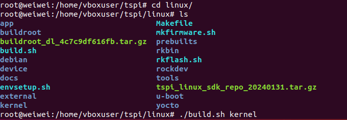
generate kernel/boot.Img, then follow the official tutorial to load the configuration file and flash it.
To use the Python driver
, first install pip3:
`sudo apt install python3-pip`.
Because I tried using the Adafruit Blinka library, but kept getting errors, saying the machine library was missing, I had to write my own driver using the periphery library. My code also uses the pywifi and numpy libraries:
`sudo pip3 install python-periphery`
`sudo pip3 install pywifi` `
sudo pip3 install numpy`
Basic communication methods:
`from periphery import SPI, GPIO
# E-ink screen SPI communication
cs = GPIO('/dev/gpiochip3', 18, "out")
dc = GPIO('/dev/gpiochip3', 2, "out")
rst = GPIO('/dev/gpiochip3', 8, "out")
busy = GPIO('/dev/gpiochip0', 15, "in")
spi = SPI("/dev/spidev3.0", 0, 48000000) # 48MHz SPI pin is SPI3 in the official pin diagram
# OLED screen I2C communication
i2c_bus = "/dev/i2c-2"
i2c = I2C(i2c_bus)`
Then consult the manuals of various screen drivers and write a driver class.
Once the screen control program is written, it can be set to start automatically on boot using crontab:
@reboot cd /home/lckfb/py && sudo python3 tspi.py


 京公网安备 11010802033920号

 74ABT16823DGGRE4


