This project originates from mengsiu's CN3058E lithium iron phosphate battery charging module project on the LCSC community: https://oshwhub.com/mengsiu/lin-suan-tie-li-5-hao-dian-chi-chong-dian-mo-kuai-cn3058e.
It adds support for 1/8W metal film resistors with 1% accuracy, a TVS diode between the input and ground, and supports various NTC thermistor usage methods, including adjustable charging voltage resistors.
It supports multiple battery cases, including two types of AA connectors and one type of AA connector SMD, one type of AAA connector and one type of AAA SMD.
Recommended temperature control settings:
Combination 1: R1 uses a 57.6KΩ resistor, R2 is unused, and the thermistor uses an NTC 100KΩ resistor with a B value of 3950K, achieving temperature control from 7-43℃.
Combination 2: R1 uses a 5.76KΩ resistor, R2 is unused, and the thermistor is an NTC 10KΩ resistor with a B
value of 3950K, achieving temperature control from 7-43℃. Combination 3: R1 uses a 6.34KΩ resistor, R2 is unused, and the thermistor
is an NTC 10KΩ resistor with a B value of 3450K, achieving temperature control from 2-43℃. Combination 4: R1 uses a 57KΩ resistor, R2 uses a 10MΩ resistor, and the thermistor is an NTC 100KΩ resistor with a B value of 3950K, achieving temperature control from 7-43℃.
Note:
The two charging circuits are identical and independent. Either one can be used, or both can be used simultaneously.
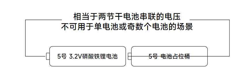
Because a single lithium iron phosphate battery is 3.2V, when using two batteries, a dummy battery must be used. Using two lithium iron phosphate batteries may damage the device.
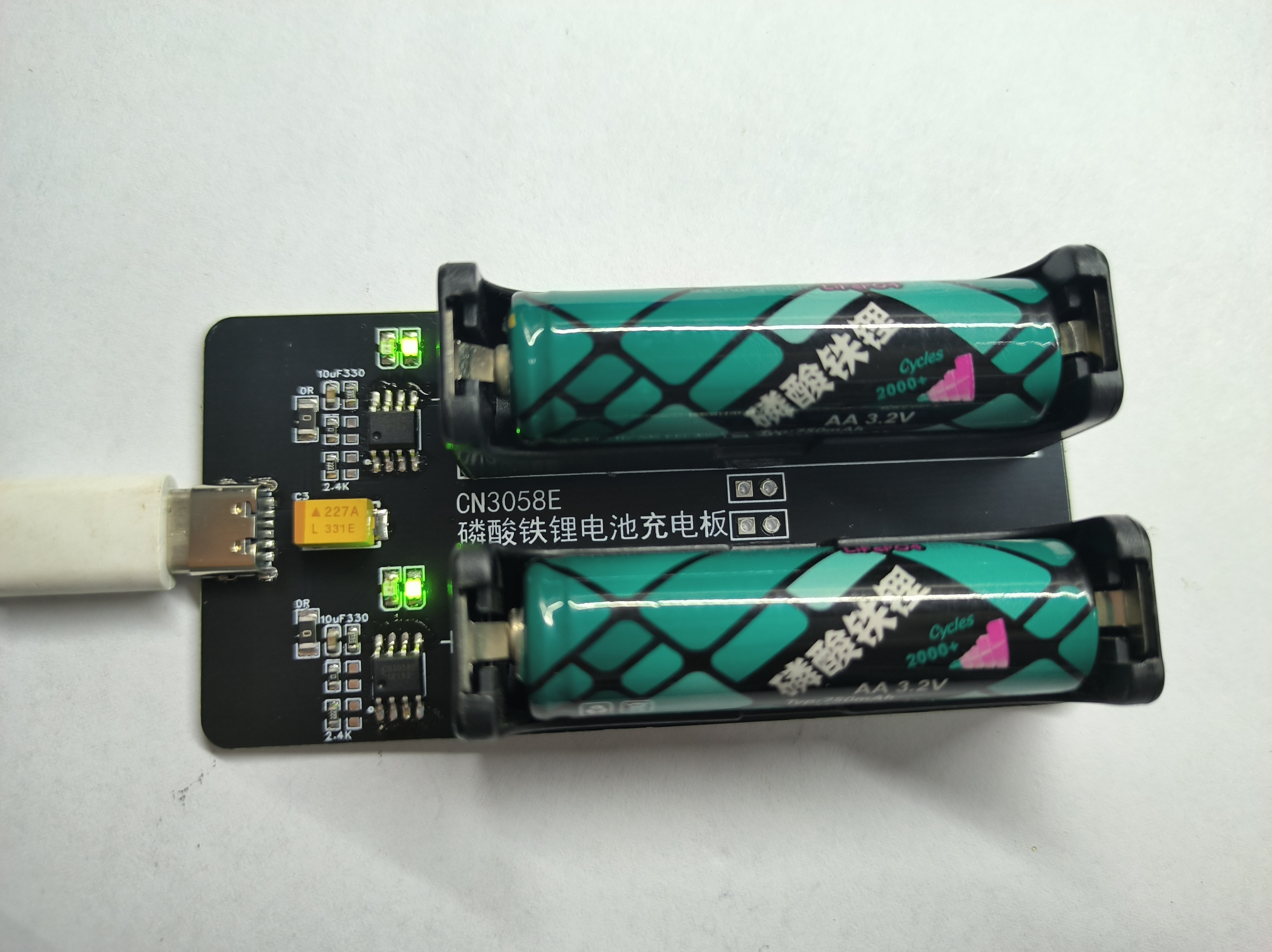
The red and green LEDs on the board are charging indicator lights; red indicates charging is in progress, and green indicates charging is complete.
R3/R4/R13 on the board are for charging current control. Resistors can be soldered as needed; two mounting points are provided to facilitate combinations of specific resistance values. The 2.4K resistor in the circuit diagram outputs a charging current of approximately 500mA.
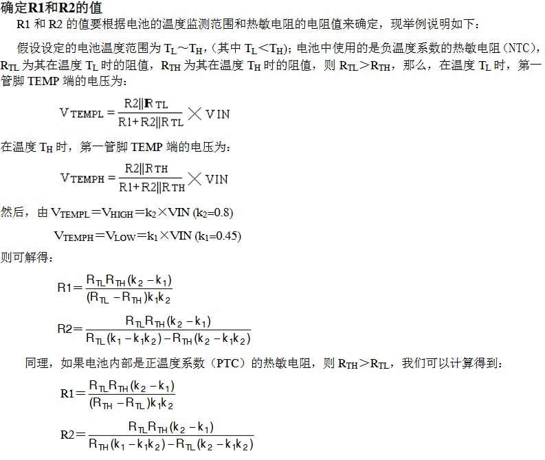
A thermistor pad is provided on the board for monitoring battery temperature during charging. R1/R2 is used to set the temperature monitoring range. If R2 is soldered with a 0Ω resistor and the TEMP pin is connected to ground, the battery temperature monitoring function will be disabled. The
charging current is set
to constant current mode. The formula for calculating the charging current is:
ICH = 1218V / RISET
, where ICH represents the charging current in amperes, and
RISET represents the resistance from the ISET pin to ground in ohms.
For example, if a charging current of 500mA is required, it can be calculated using the following formula:
RISET = 1218V/1A = 1.218kΩ.
To ensure good stability and temperature characteristics, it is recommended to use a 1% accuracy metal film resistor for RISET.
The charging current can be detected by measuring the voltage at the ISET pin. The charging current can be calculated using the following formula:
ICH = (VISET / RISET) × 1000 ( See the finished
product image


below.)
Why make this board?
We use AA batteries in many places, and often two 1.5V batteries are used. In situations where batteries are used extensively, the cost of battery consumption can be considerable.
Years ago, lithium iron phosphate batteries existed. These are rechargeable, with each cell at 3.2V, equivalent to two ordinary AA batteries, and a discharge current greater than ordinary alkaline batteries.
When these batteries were purchased, the accompanying chargers were 220V, which wasn't very convenient in actual use. It was even more inconvenient for outdoor use.
Analyzing the charger circuit, the charging chip used is CN3058E, with a supply voltage of 3.8V to 6V. This means that ordinary mobile phone chargers, car chargers, and power banks can all power it.
This board was created to charge two lithium iron phosphate batteries separately, which should be sufficient for outdoor use.
Important notes:
The two charging circuits are identical and independent; either circuit can be used, or both can be used simultaneously.
Because a single lithium iron phosphate battery is 3.2V, a dummy battery must be used with two batteries. Using two lithium iron phosphate batteries may damage electrical appliances.
The red and green LEDs on the board are charging indicators; red indicates charging and green indicates charging is complete.
R3/R4 on the board controls the charging current. Resistors can be soldered as needed; two mounting points are provided to facilitate specific resistance values. The 2.4K resistor in the circuit diagram outputs a charging current of approximately 500mA.
A thermistor pad is provided on the board for monitoring battery temperature during charging. R1/R2 is used to set the temperature monitoring range. If R2 is soldered with a 0Ω resistor and the TEMP pin is grounded, the battery temperature monitoring function will be disabled.
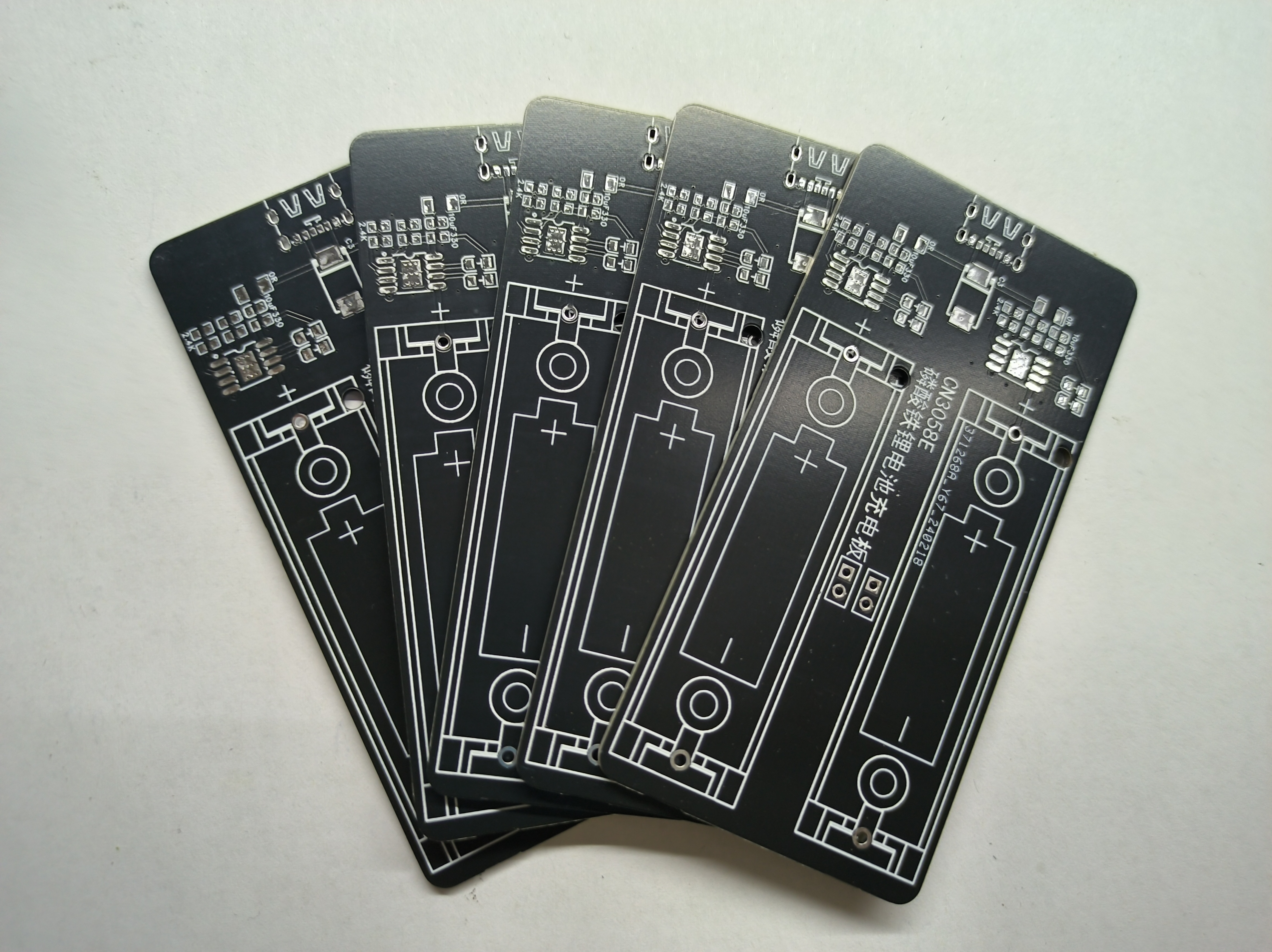
I didn't make a casing for it because the JLCPCB circuit board is of decent quality and strong enough for everyday use, plus the black circuit board looks pretty good, so I opted for a barebones design. However, I might add a casing later.
(The

above is an excerpt from the original author's content.)


 京公网安备 11010802033920号

 C052C229H1R5TA


