Video Link:
Project Introduction (
Please fill in the basic introduction of the project here. Example:
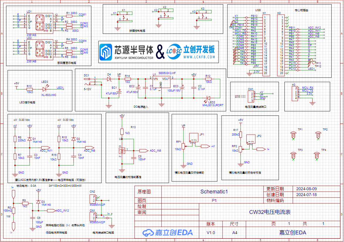
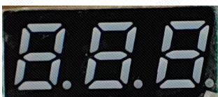
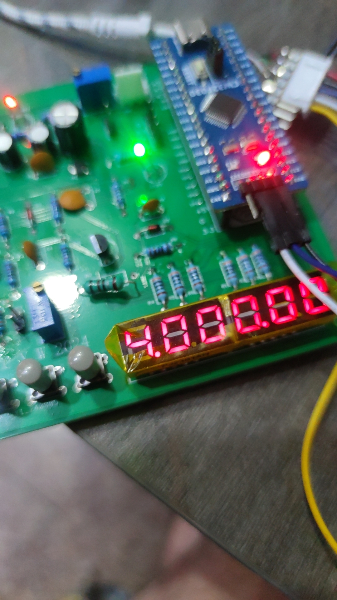
This project is a voltage and current detection based on the SW32 microcontroller. Voltage and current are acquired and converted through two ADC channels respectively. The digital tube is a six-digit display, with the top three digits displaying the voltage value and the bottom three digits displaying the current value. A continuous acquisition mode can be used in the program. It also features a digital voltmeter and ammeter with calibration function.
Project Function
: Measures current and voltage.
Project Parameters:
COM1, COM2, and COM3 bit code pins. These three bit code pins control the on/off state of the three digital tubes respectively, and are active low.)
/ Common cathode seven-segment tube encoding table:
0x3f 0x06 0x5b 0x4f 0x66 0x6d 0x7d 0x07 0x7f 0x6f
0 1 2 3 4 5 6 7 8 9
0xbf 0x86 0xdb 0xcf 0xe6 0xed 0xfd 0x87 0xff 0xef
0. 1. 2. 3. 4. 5. 6. 7. 8. 9. /
//0x3f, 0011 1111; 0x5b 0101 1011
uint8_t Seg_Table[20] = {0x3f, 0x06, 0x5b, 0x4f, 0x66, 0x6d, 0x7d, 0x07, 0x7f, 0x6f,
0xbf, 0x86, 0xdb, 0xcf, 0xe6, 0xed, 0xfd, 0x87, 0xff, 0xef};
void Seg_Configuration(void) //Find the schematic and initialize the relevant pins of the digital tube
{
__RCC_GPIOA_CLK_ENABLE(); //Turn on the clock of GPIOA
__RCC_GPIOB_CLK_ENABLE(); //Turn on the clock of GPIOB
GPIO_InitTypeDef GPIO_InitStruct;
GPIO_InitStruct.Pins = GPIO_PIN_2 | GPIO_PIN_0 | GPIO_PIN_4 | GPIO_PIN_6 | GPIO_PIN_7 | GPIO_PIN_1 | GPIO_PIN_3 | GPIO_PIN_5 | GPIO_PIN_8 | GPIO_PIN_11 | GPIO_PIN_12 | GPIO_PIN_15;
//A:PA02;B:PA00;C:PA04;D:PA06;E:PA07;F:PA01;G:PA03;DP:PA05;
//COM1:PA08;COM2:PA11;COM3:PA12;COM4:PA15;COM5:PB03;COM6:PB04;
GPIO_InitStruct.Mode = GPIO_MODE_OUTPUT_PP;
GPIO_InitStruct.IT = GPIO_IT_NONE;
GPIO_InitStruct.Speed = GPIO_SPEED_HIGH;
GPIO_Init(CW_GPIOA, &GPIO_InitStruct);
GPIO_InitStruct.Pins = GPIO_PIN_3 | GPIO_PIN_4; //COM5:PB03;COM6:PB04
GPIO_InitStruct.Mode = GPIO_MODE_OUTPUT_PP;
GPIO_InitStruct.IT = GPIO_IT_NONE;
GPIO_InitStruct.Speed = GPIO_SPEED_HIGH;
GPIO_Init(CW_GPIOB, &GPIO_InitStruct);
}oid Seg_Dis(uint8_t Pos,uint8_t Num)
{
//The voltmeter and ammeter have two digital tubes. We will use the upper tube in this case, so the lower digital tube is turned off.
GPIO_WritePin(CW_GPIOA,GPIO_PIN_15,GPIO_Pin_SET); //PA15,COM4
GPIO_WritePin(CW_GPIOB,GPIO_PIN_3,GPIO_Pin_SET); //PB03,COM5
GPIO_WritePin(CW_GPIOB,GPIO_PIN_4,GPIO_Pin_SET); //PB04,COM6
int i;
uint8_t Dis_Value = Seg_Table[Num];
for(i = 0; i < 8; i++)
{
switch(i)
{
case 0:
GPIO_WritePin(CW_GPIOA,GPIO_PIN_2,(Dis_Value >> i) & 0x01); //PA02,A
break;
case 1:
GPIO_WritePin(CW_GPIOA,GPIO_PIN_0,(Dis_Value >> i) & 0x01); //PA00,B
break;
case 2:
GPIO_WritePin(CW_GPIOA,GPIO_PIN_4,(Dis_Value >> i) & 0x01); //PA04,C
break;
case 3:
GPIO_WritePin(CW_GPIOA,GPIO_PIN_6,(Dis_Value >> i) & 0x01); //PA06,D
break;
case 4:
GPIO_WritePin(CW_GPIOA,GPIO_PIN_7,(Dis_Value >> i) & 0x01); //PA07,E
break;
case 5:
GPIO_WritePin(CW_GPIOA,GPIO_PIN_1,(Dis_Value >> i) & 0x01); //PA01,F
break;
case 6:
GPIO_WritePin(CW_GPIOA,GPIO_PIN_3,(Dis_Value >> i) & 0x01); //PA03,G
break;
case 7:
GPIO_WritePin(CW_GPIOA,GPIO_PIN_5,(Dis_Value >> i) & 0x01); //PA05,DP
break;
default:
break;
}
}
switch(Pos)
{
case 1:
GPIO_WritePin(CW_GPIOA,GPIO_PIN_8,GPIO_Pin_RESET); //PA08,COM1
GPIO_WritePin(CW_GPIOA,GPIO_PIN_11,GPIO_Pin_SET); //PA11,COM2
GPIO_WritePin(CW_GPIOA,GPIO_PIN_12,GPIO_Pin_SET); //PA12,COM3
break;
case 2:
GPIO_WritePin(CW_GPIOA,GPIO_PIN_8,GPIO_Pin_SET); //PA08,COM1
GPIO_WritePin(CW_GPIOA,GPIO_PIN_11,GPIO_Pin_RESET); //PA11,COM2
GPIO_WritePin(CW_GPIOA,GPIO_PIN_12,GPIO_Pin_SET); //PA12,COM3
break;
case 3:
GPIO_WritePin(CW_GPIOA,GPIO_PIN_8,GPIO_Pin_SET); //PA08,COM1
GPIO_WritePin(CW_GPIOA,GPIO_PIN_11,GPIO_Pin_SET); //PA11,COM2
GPIO_WritePin(CW_GPIOA,GPIO_PIN_12,GPIO_Pin_RESET); //PA12,COM3
break;
default:
break;
}
})
Principle Analysis (Hardware Description)
Notes:
This section can be used to fill in key points or common mistakes during design and manufacturing. Example:
Note the orientation and spacing of the SW32 module.
Note the 8533 components;
the grounding path should be the 8550 power supply location .
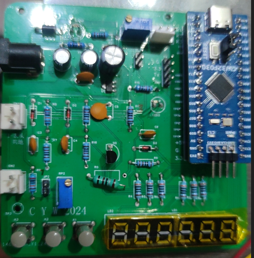
Assembly Process :
Soldering: Note the polarity of the plug-in capacitors;
solder them in order of height, starting with the highest components.
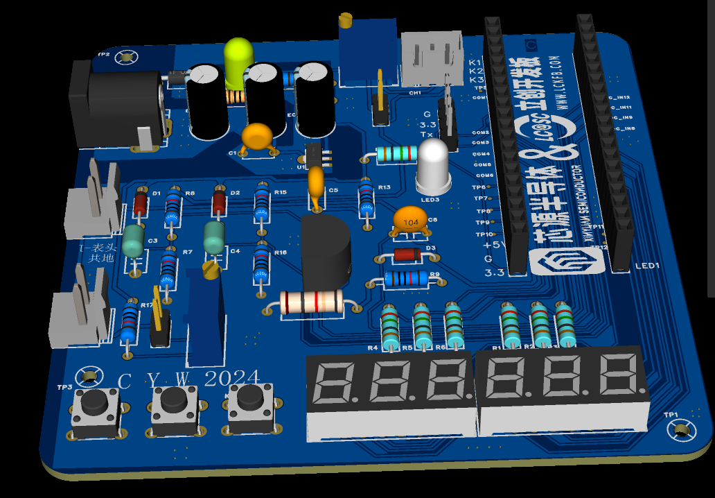
Actual product image
PDF_CW32 Voltage and Current Meter.zip
Altium_CW32 voltage and current meter.zip
PADS_CW32 Voltage and Current Meter.zip
BOM_CW32 Voltage and Current Meter.xlsx
92596
STC8H8K64U LQFP64 core board
STC8H8K64U LQFP64 core board
The STC LQFP64 packaged minimum core board
is compatible with the STC8H8K64U and STC12G32K.
The STC12G32K is a small board (3.8cm * 3.8cm) that is packed with features, including
all I/O ports brought out.
It is compatible with both the 8H8K and 12G32K, making it suitable for various embedded applications and offering plug-and-play functionality.
WeChat image_20240722035322.jpg
PDF_STC8H8K64U LQFP64 core board.zip
Altium_STC8H8K64U LQFP64 core board.zip
PADS_STC8H8K64U LQFP64 core board.zip
BOM_STC8H8K64U LQFP64 core board.xlsx
92599
Liangshan School Smart Car
The toy car is made using the Liangshan style, differing from the official version in the size of the board. It features Bluetooth and tracking capabilities.
Project Highlights
(1) PCB: The boards used in this project are within 10x10, which can be made for free. Flexible boards are used to connect the battery, which reduces the size of the power supply.
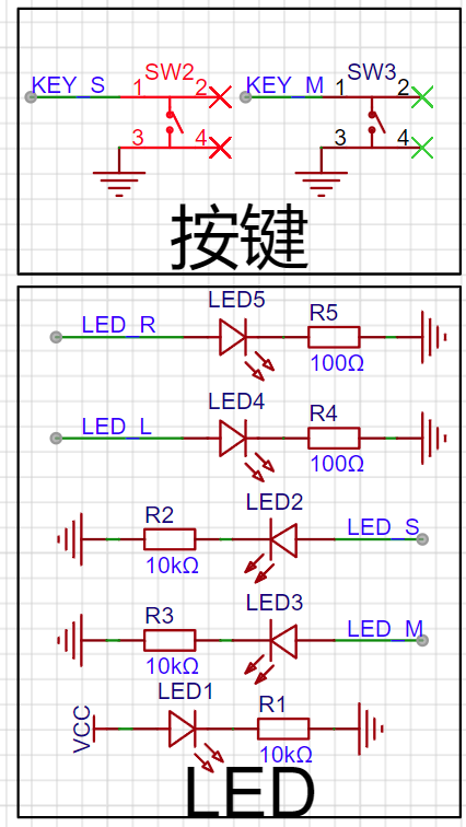
(2) The Liangshanpai Smart Car is equipped with two LED lights in front, one on each side, which can be used to simulate the status of car lights when driving or passing other cars.
(3) The Liangshanpai Smart Car has two independent buttons, namely KEYS and KEYM, which can be used to start and switch between motion modes.
(4) The Liangshanpai Smart Car is equipped with a buzzer, which can be used to sound an alarm when encountering obstacles, and can also use a timer to change its output frequency to play music.
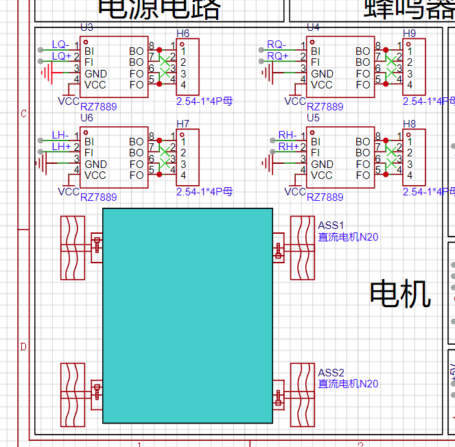
(5) The Liangshanpai Smart Car is equipped with four motor drives and four N20 motors, which can realize PWM output and speed adjustment functions.
(6) The Liangshanpai Smart Car is equipped with five infrared tracking, which can be used to follow the black line, learn the use of comparator circuit, and realize the tracking function.
(7) The Liangshanpai Smart Car is equipped with HCSR04 ultrasonic module interface circuit, which can realize ultrasonic obstacle avoidance function by learning the module principle and the underlying driver code.
(8) The Liangshanpai Smart Car uses the ADC function on the development board to detect the car's battery level, making it convenient for us to charge it in time;
(9) The Liangshanpai Smart Car provides an HC-05 Bluetooth module interface circuit, which can be used with a mobile phone Bluetooth APP to realize the function of wireless remote control of the car;
Car circuit design
1. Power input module;


Two gold fingers are reserved for power supply, which can save space
2. Button indicator: car lights, button module;
3. Buzzer module;

4. ADC voltage acquisition circuit;

5. N20 motor drive circuit;
6. Four-way tracking circuit;

7. HC-SR04 ultrasonic module;

8. HC-05 Bluetooth module;

2_Software Data.zip
WeChat_20240821214420.mp4
WeChat_20240821214424.mp4
WeChat_20240821214429.mp4
WeChat_20240821214433.mp4
WeChat_20240821214436.mp4
WeChat_20240821214439.mp4
1_Teaching Documents.zip
3_Hardware Documentation.zip
PDF_Liangshan School Smart Car.zip
Altium_Liangshanpai Smart Car.zip
PADS_Liangshanpai Smart Car.zip
BOM_Liangshanpai Smart Car.xlsx
92600
PCB Motor - 12N16P
This is a PCB motor, model 12N16P, made using a 6-layer board. The design has been validated and is ready for prototyping. It has a simple structure, and the rotor can be 3D printed.
Design Purpose:
To adapt to certain special application scenarios, such as those requiring extremely small size and thickness, a brushless motor with axial flux is a good choice. Therefore, I designed this PCB motor, with an overall thickness of less than 1cm, using a 12N16P design. Testing showed it can start and run normally even without sensors, with low operating noise. It is made using a 6-layer board, allowing for direct prototyping.
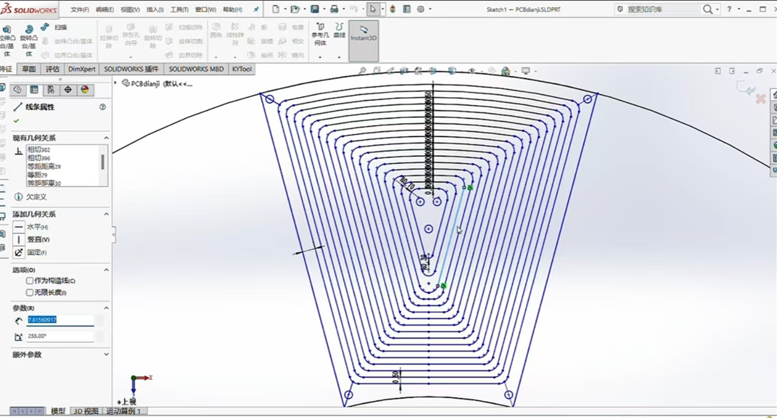
PCB Design:
Drawing the PCB motor coils on EDA software is difficult. It was first drawn using CAD software, then exported as a DXF file to JLCPCB EDA for coil design.

Structural Design:
The magnets used here are rectangular, arranged in an NSNSNSNSNS... pattern.

Operational
Testing: It requires only 18V to start normally and is ready for use.

PCB motor.mp4
PDF_PCB Motor-12N16P.zip
Altium_PCB Motor-12N16P.zip
PADS_PCB Motor-12N16P.zip
92601
STC32 USB-CAN Communication Module
USB to CAN converter
Project Description
Main Functions:
1. USB-CAN communication module
2. Message display with OLED
3. WIFI module, can connect to host computer via WIFI
Schematic:
Core peripheral circuit Future Studio's reference minimum system, no serial port version
https://oshwhub.com/wei-lai-dian-zi-gong-zuo-shi/zui-xiao-xi-tong-stc32g12k128-hid-xia-zai
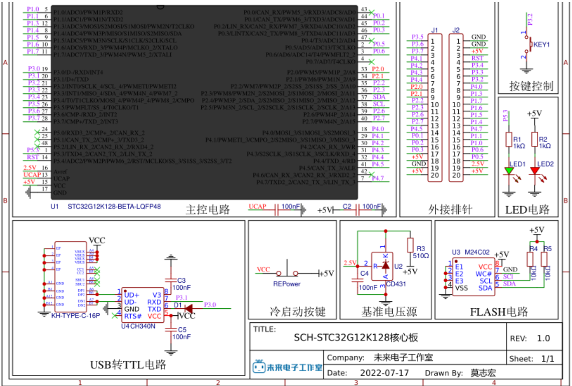
WIFI interface, ESP01S

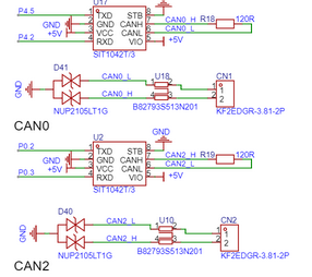
uses two CAN channels, the chip is the domestic SIT1042T.
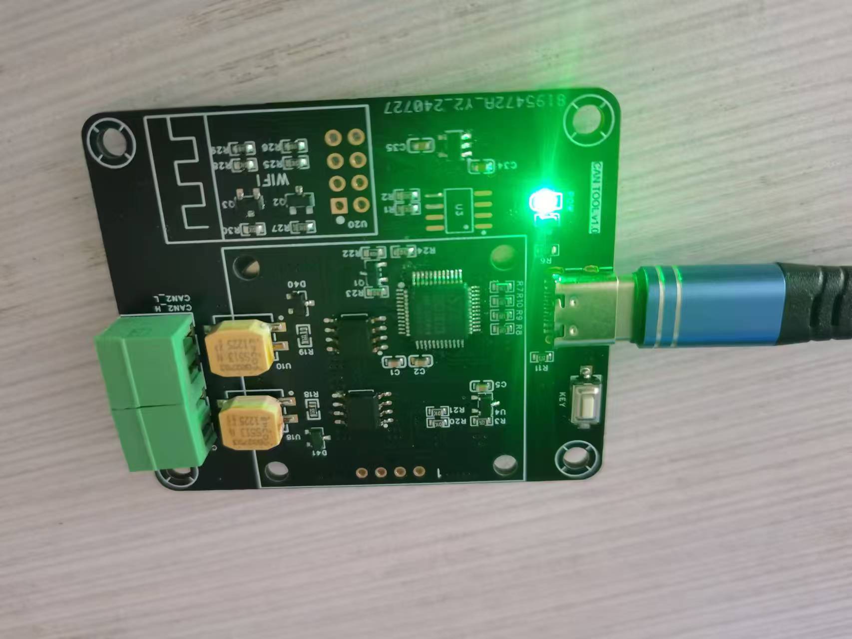
Verification effect, power supply test OK, using STC-ISP software, operation is consistent with the manual, but it is not recognized, and the STC USB Writer is not displayed. The board was resoldered once, but it is still the same. However, I am using the same chip. I suspect that the chip may be broken. I have been struggling with it for a long time, so I gave up on
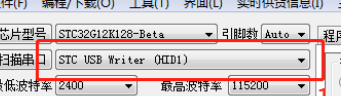
the physical pictures.
PDF_STC32 USB-CAN Communication Module.zip
Altium_STC32 USB-CAN communication module.zip
PADS_STC32 USB-CAN communication module.zip
BOM_STC32 USB-CAN Communication Module.xlsx
92603
The STM32F103 flight controller uses Naza firmware.
Based on the STM32F103 flight controller, the pins are designed according to the Naza firmware.
Reserved PWM (unverified)
onboard brushed driver (verified and test-flown)
with 1s power supply.
d0fbc65634c04c299ae3df69699b200f.mp4
betaflight_3.2.5_NAZE.hex
PDF_stm32f103 flight controller using Naza firmware.zip
Altium_stm32f103 flight controller uses Naza firmware.zip
PADS_stm32f103 flight controller uses Naza firmware.zip
BOM_stm32f103 flight controller uses Naza firmware.xlsx
92604
Minimum system and procedures for controlling servo motors
It can control four servos, plus a P0 expansion port.
Project Functionality This design is based on the STC89C51/52 microcontroller and is a minimum system software code
for controlling a servo motor. #include "reg52.h" #include "intrins.h" #include "TMER0.H" sbit S1=P0^0; sbit S2 =P0^1; sbit SG_PWM1=P2^0; sbit SG_PWM2=P2^1; sbit SG_PWM3= P2^2; sbit SG_PWM4=P2^3; unsigned char count=0; unsigned char PWM1_count=0; unsigned char PWM2_count=0; unsigned char PWM3_count=0; unsigned char PWM4_count=0; void Delay1ms(unsigned int xms ) //@11.0592MHz { while(xms) { unsigned char data i, j; i = 15; j = 90; do { while (--j); } while (--i); xms--; } } void main() { Timer0_Init(); S1 = 1 ; PWM1_count=1; Delay1ms ( 100) ; Delay1ms(100); PWM1_count=3; Delay1ms (100) ; PWM2_count=3; Delay1ms (100); PWM3_count = 3 ; Delay1ms ( 100 ) ; PWM1_count=3; PWM4_count=3; } else { PWM1_count=1; PWM4_count=1; Delay1ms(100); PWM2_count=3; PWM3_count=3; } } } unsigned int T0Count; void Timer0_Routine() interrupt 1 { TL0 = 0x33; //??????? TH0 = 0xFE; //??????? count++; count%=40; if(count<PWM1_count) { SG_PWM1=1; } else { SG_PWM1=0; } if(count<PWM2_count) { SG_PWM2=1; } else { SG_PWM2=0; } if(count<PWM3_count) { SG_PWM3=1; } else { SG_PWM3=0; } if(count<PWM4_count) {
SG_PWM4=1;
}
else
{
SG_PWM4=0;
}
}
Note:
For cold start downloading of the microcontroller, when using the P0 serial port, you need to solder pull-up resistors yourself. Also,
please note
that the Comtasia company logo is from the Cyberpunk 2077 game; any resemblance is purely coincidental.
Servo control program.txt
PDF_Minimum System and Programs for Controlling Servo Motors.zip
Altium_Minimum System and Programs for Controlling Servo Motors.zip
PADS_Minimum System and Programs for Controlling Servo Motors.zip
92605
electronic


 京公网安备 11010802033920号

 HLMP-CM31-UR000


