I. Design Background
This design was developed as part of a learning activity at LCSC. The primary technology used is ADC (Analog-to-Digital Converter). ADCs are indispensable components in electronic systems, converting continuous analog signals into digital signals, enabling digital processing and analysis. ADCs play a crucial role in signal conversion, measurement and data acquisition, control system input, and communication and signal processing. Their widespread application promotes the intelligent and precise control of electronic equipment across various industries, and is a key factor driving modern technological progress.
Digital voltmeters and ammeters combine ADC technology with circuit measurement principles, accurately converting analog voltage and current signals into digital displays for easy reading and analysis by electronic engineers. This device not only improves the accuracy and efficiency of circuit measurements but also helps engineers better understand circuit behavior, making it a powerful tool for electronic design and troubleshooting, significantly supporting the work of electronic engineers. In product applications, digital voltmeters ensure the accuracy and safety of circuit design, while also providing strong support for product quality control and subsequent maintenance.
II. Knowledge Learned During the Design Process
1. How to Select Chips: Chip selection is based on product requirements. First, we need to confirm the required number of pins, including the number of reusable pins for SPI, IIC, USART, and ADC. Then, we consider the operating voltage, the product's voltage, and cost-effectiveness to select a suitable chip. Based on the product's needs, the CW32 main control chip was found to be more suitable among multiple chips, offering significant advantages:
Wide operating temperature range: -40~105℃;
Wide operating voltage range: 1.65V~5.5V (STM32 only supports 3.3V systems);
Strong anti-interference: HBM ESD 8KV; All ESD reliability reaches the highest international standard level (STM32 ESD 2KV)
; Project focus - Better ADC: 12-bit high-speed ADC, achieving ±1.0LSB INL 11.3ENOB; Multiple Vref reference voltages... (STM32 only supports VDD=Vref);
Stable and reliable eFLASH technology. (Flash0 pending)
2. The circuit includes reverse connection protection. Reverse connection protection circuits include series diodes and anti-parallel diodes + fuses. However, series diodes have a disadvantage: voltage drop. Silicon diodes have a voltage drop of 0.7V, while germanium diodes only have a voltage drop of 0.15V. Therefore, the commonly used reverse connection protection circuit is an anti-parallel diode + fuse.
3. A clamping diode is also added to the voltage measurement area to prevent damage to the chip pins. When the measured voltage is too high, resulting in a voltage difference greater than 5.7V after voltage division, the diode will conduct, limiting the voltage across its terminals and protecting the microcontroller pins. Note: A diode conducts when the voltage difference across its terminals exceeds a certain threshold; the other terminal does not necessarily need to be ground.
Because the voltage difference of a diode is constant, when a high voltage is applied, if the other terminal is 5V, the voltage will be limited to around 5.7V.
Clamping in circuits refers to limiting voltage, and diode clamping specifically refers to the technique of using a diode to limit the potential at a certain point in the circuit.
Diode clamping primarily utilizes the unidirectional conductivity of a diode. When the voltage across the positive terminal of the diode is greater than the voltage across the negative terminal and the diode conducts, the voltage across the diode is limited to its voltage drop.
The clamping process: Through the clamping action of the diode, the clamped potential is forcibly pulled towards the reference terminal, thereby limiting the potential. Clamping does not change the waveform of the original signal; it only raises or lowers the reference potential of the signal.
Depending on the diode connection method, clamping circuits can be divided into positive clamping circuits and negative clamping circuits. This project only designs positive clamping. (Positive electrode material)
Positive clamping circuit: When the positive terminal of the diode is grounded, it is a positive clamping circuit. During the positive half-cycle, the diode is cut off; during the negative half-cycle, the diode conducts, and the capacitor is charged to a certain voltage, limiting the output voltage within a certain range.
Negative clamping circuit: When the negative terminal of the diode is grounded, it is a negative clamping circuit. The working principle is the opposite of the positive clamping circuit.
4. When writing code, some problems are encountered, such as the digital tube display not working properly. Why is this? Because the corresponding digit wasn't turned off after each digit was displayed, modifying the displayed value affected the previous digit the next time it was accessed. Therefore, after displaying the value of one digit of the LED display, all digits should be turned off before restarting segment and digit selection.
III. Voltage Detection Resistor Value Design:
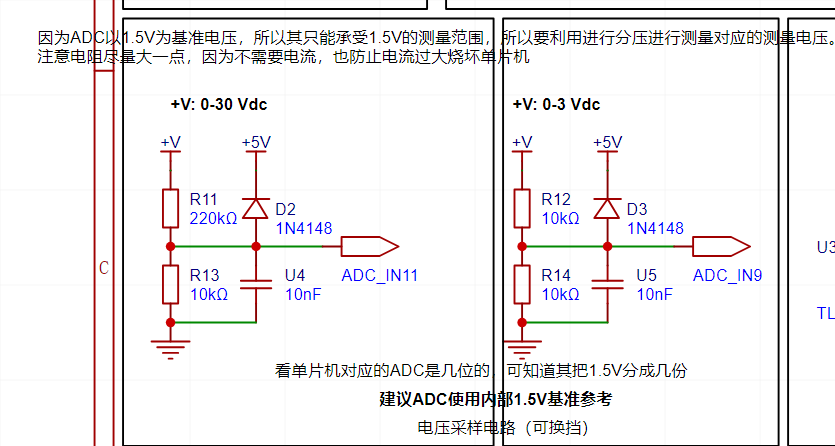
The reference voltage for ADC detection can be selected; a 1.5V voltage value was chosen in the design. How to choose a reasonable resistor value? Taking 3V as an example: when the ADC is fully detected, the maximum external voltage is 1.5V. However, 3V needs to be detected, so we need to perform voltage division, meaning that when the external voltage is 3V, the ADC detects a voltage of 1.5V. By calculating 3/(R15+R16)*R16=1.5, we know that R16/(R15+R16)=1/2, meaning the resistance value of R16 accounts for half of the total resistance value. Since the main purpose is voltage testing, a large resistor should be chosen to minimize current and prevent damage to the pins. Therefore, a 10K resistor value was chosen.
Some might argue that measuring a 30V resistor is incorrect, as the ideal resistance ratio should be R7/(R8+R7) = 1/20. This is because standard resistor values rarely exceed 200KΩ, so a close value is chosen.
IV. Resistor Value Design for Current Sensing:
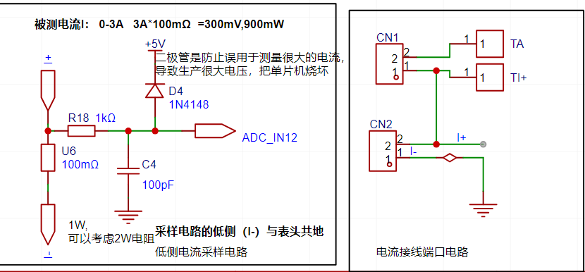
The sampling current in this project is 3A, and the selected sampling resistor (R0) is 100mΩ.
The selection of the sampling resistor mainly considers the following aspects:
the maximum designed measurement current,
the voltage difference caused by the 3A current sensing resistor in this project, and generally, it is not recommended to exceed 0.5V.
The power consumption of the current sensing resistor should be selected based on this parameter. Considering the power consumption (temperature) issue under high current, a 1W packaged metal wire-wound resistor was selected.
Voltage amplification factor across the current sensing resistor: No operational amplifier was used in this project to build the amplification circuit, therefore the amplification factor is 1.
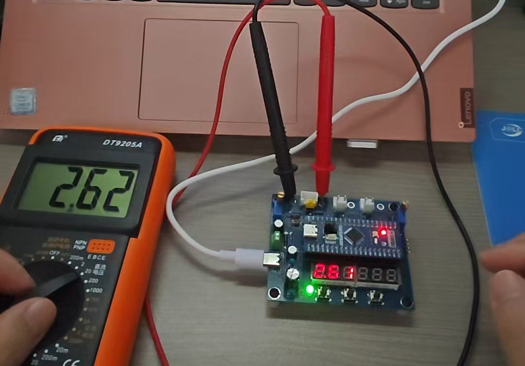
V. Product Showcase


 京公网安备 11010802033920号

 ICS951411


