 The device uses a 600mAh battery as the main power source. Through an AMS1117 voltage regulator, the battery voltage is converted to a stable 3.3V voltage to meet the power supply requirements of the development board. The device charges via a TYPE-C interface using a TP4056 charging module. The charging current is set to 580mA to ensure a balance between charging speed and battery health. To save power, the device has a sliding switch that can disconnect the battery power supply when the device is not in use, thereby extending battery life.
  The voltage divider resistors in this project are 220K+10K, resulting in a voltage division ratio of 22:1. The ADC reference is 1.5V, which can be configured via the program. The maximum voltage to be measured is 0-30V for safety reasons.
  This project uses a low-side current sampling circuit for current detection. The low-side of the sampling circuit is grounded to the development board via a 0Ω resistor. The current input range is 0-3A, the sampling resistor is 2512 100mΩ, the accuracy is ±1%, and the power is 1W.
 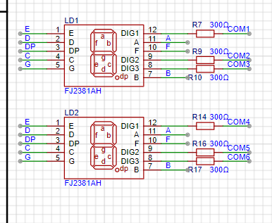 This project uses two 0.28-inch three-digit common-cathode digital tubes as display units.
 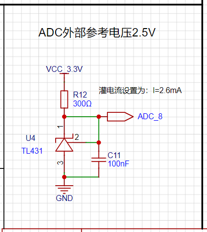 This project adds an additional TL431 circuit to provide a 2.5V reference voltage, which can be used to provide an external voltage reference for ADC calibration.
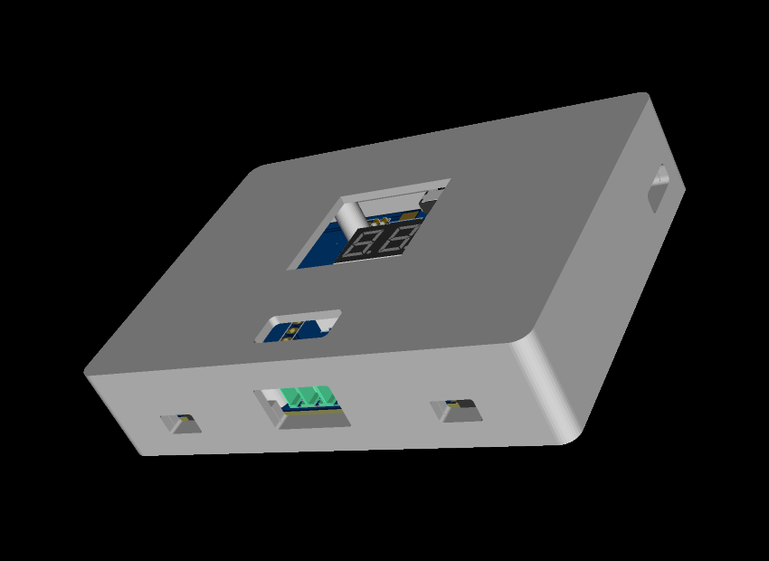 a board size of 56x74mm and a 3D shell size of 60x82x18mm.
 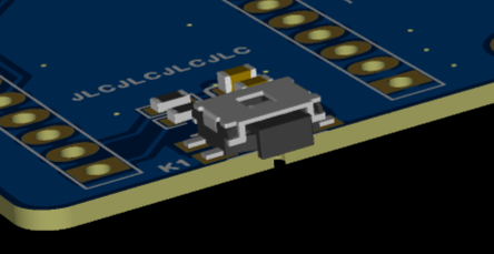 The button uses a horizontal, side-mounted interface for
  testing voltage and current, which is a screw-type terminal block. This type of terminal block provides a reliable electrical connection, ensuring stable current transmission. Screw-type terminals are relatively simple to operate, generally requiring only a screwdriver to complete the wiring, improving testing efficiency.
  The battery connection uses a pluggable terminal block for easy connection and disconnection during debugging.


 Notes:
All reference designs on this site are sourced from major semiconductor manufacturers or collected online for learning and research. The copyright belongs to the semiconductor manufacturer or the original author. If you believe that the reference design of this site infringes upon your relevant rights and interests, please send us a rights notice. As a neutral platform service provider, we will take measures to delete the relevant content in accordance with relevant laws after receiving the relevant notice from the rights holder. Please send relevant notifications to email: bbs_service@eeworld.com.cn.
It is your responsibility to test the circuit yourself and determine its suitability for you. EEWorld will not be liable for direct, indirect, special, incidental, consequential or punitive damages arising from any cause or anything connected to any reference design used.
Supported by EEWorld Datasheet
EEWorld
subscription
account

EEWorld
service
account

Automotive
development
community

Robot
development
community

About Us Customer Service Contact Information Datasheet Sitemap LatestNews


Room 1530, 15th Floor, Building B,
No.18 Zhongguancun Street,
Haidian District,
Beijing, Postal Code: 100190
China
Telephone: 008610 8235 0740
 京公网安备 11010802033920号

 223886914688


