Warning: Building a switching power supply is inherently dangerous. All parameters in this design have not been verified, and I do not guarantee the correctness of any circuits, parameters, or formulas used in this design. Replicating or referencing this work requires you to assume all possible risks yourself. Please ensure you are a fully capable and responsible individual!!!
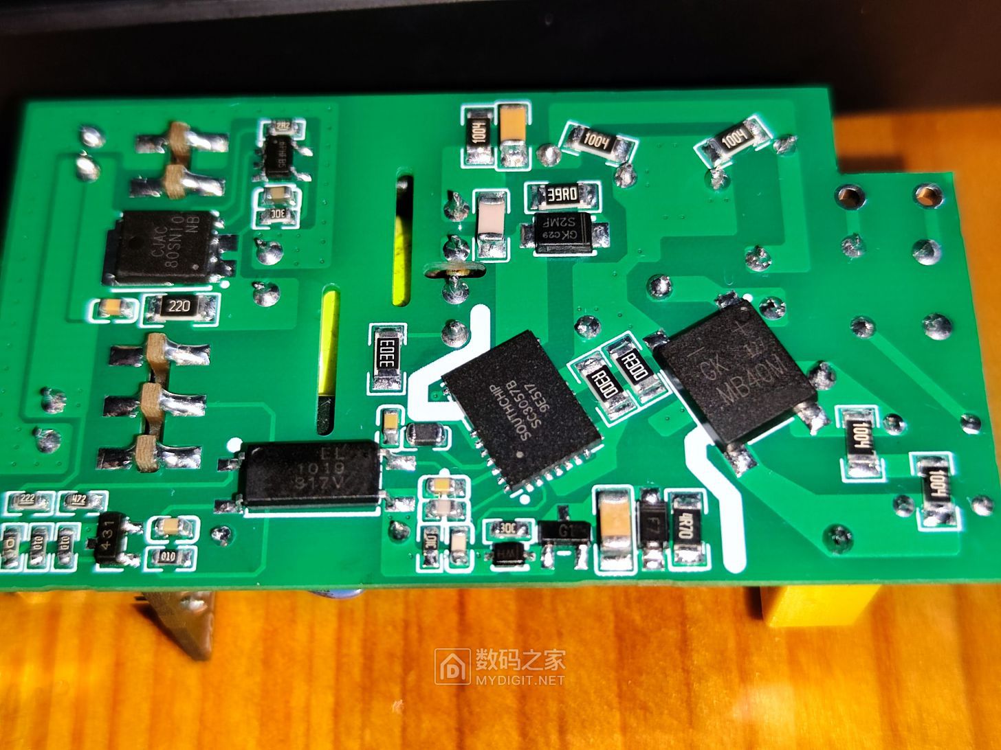
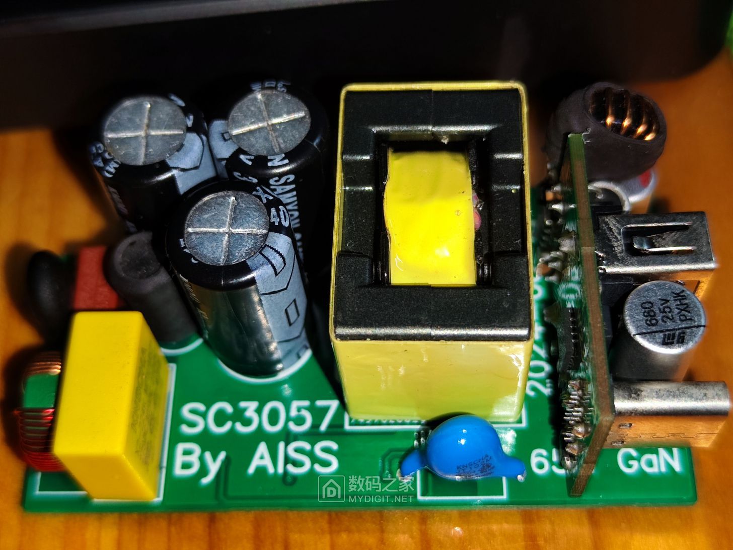
Digital Home First Article: Building a GaN Power Supply with a Southchip SC3057 Solution.
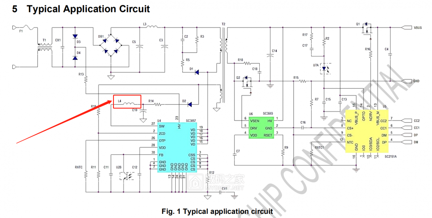
Several months later, I'm back to playing with switching power supplies. Although the solution is a common flyback, the Southchip SC3057 chip has too many pitfalls;
it's easy to fall into a trap if you're not careful. Why? Mainly because it adds an internal boost controller
, and this controller is truly absurd. Why put such a mess in a perfectly good flyback power supply? The chip is expensive and difficult to debug.
I've already made three boards and wasted five chips. Each chip costs over five yuan…

I really don't understand the chip design thinking. If you want to increase the chip's VDD range,
why not add more chips? The VDD pin has a withstand voltage, but the boost converter was integrated into
the first board. The inductor issue was overlooked, causing the chip to burn out after power-on.
After checking, I found a missing inductor. This chip is also particularly prone to damaging the optocoupler pins;
the pin layout is unreasonable, with dense pins, which is bad for soldering.
To make it work on such a small board, I removed the RC filter network on the RCS current sensing resistor
and also the RNTC resistor, relying solely on internal temperature protection.
However, the chip's protection is poor; the optocoupler pin and FB feedback pin broke down after only a few tests with an oscilloscope probe.
The third pitfall is the startup problem; the VDD startup capacitor must be used according to the recommended value.
I used 2.2uF. It won't start with 25V instead of 50V.
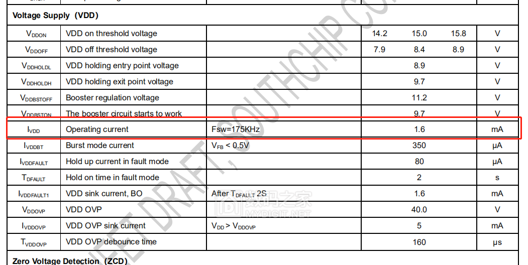
The boost inductor and capacitor on the SW pin are also problematic. The datasheet specifies that the maximum operating current of VDD is 1.6mA,
so only a 0805 inductor package with an inductance of 22uH can be selected.
I suspect the DC derating of the MLCC capacitor is causing a decrease in capacitance, resulting in
insufficient capacitance at high voltages. However, this presents another issue:
its normal startup voltage is 15V. Theoretically, a 25V 2.2uF capacitor should be sufficient,
but in reality, it keeps restarting and cannot work.
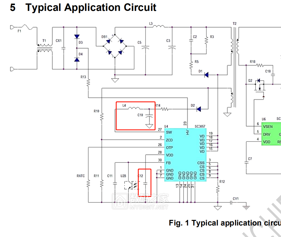
Later, I discovered that the power supply from SW is backflowing to the VDD pin. If the voltage on the SW pin is not constant,
it remains in a restart state. It's still the same problem with the filter capacitor
. This startup issue is incredibly troublesome. Moreover, if you directly supply power to the VDD pin, the chip won't work;
it must supply power to the SW pin to start normally. It's really difficult to fix.
This chip has only one advantage: its built-in gallium nitride power transistor has a built-in impedance of only 165mΩ, easily achieving 120W on a bare board at room temperature.
Unlike the Dongke DK065G, the compensation network parameters of the TL431 have been changed.
Directly applying Dongke's compensation network parameters will cause problems with the startup of the SW2303
, resulting in the SW2303 failing to start and operate normally after power-on.
After modifying it to 10nF and 100K, the SW2303 operates stably.

To ensure compatibility with the transformer I previously prototyped, a series voltage regulator circuit was added.
The feedback winding voltage of this transformer can reach 60V.
The supply voltage range of the Southchip SC3057 cannot meet the requirements, and under full load, it may cause the chip to burn out.

——————————————————————————————————————
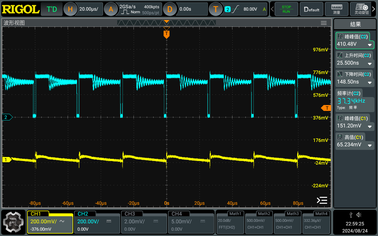
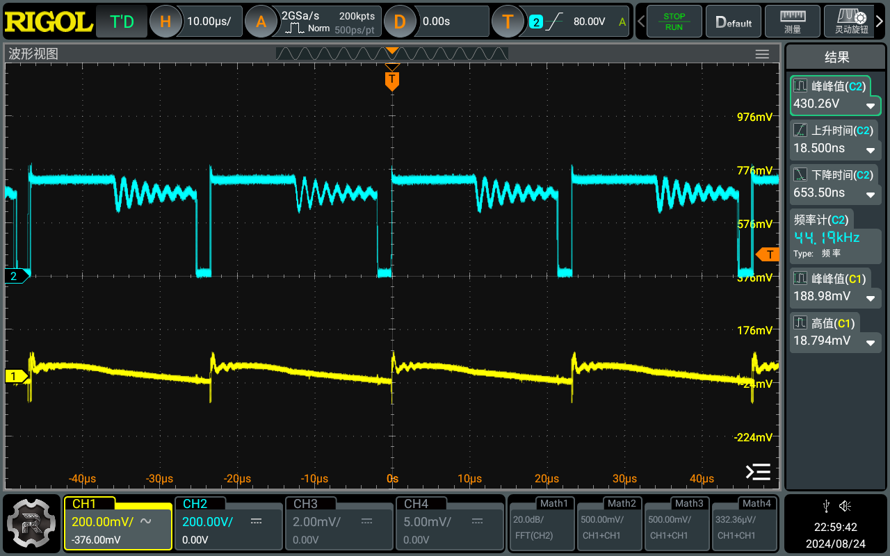
Next are the actual test data. The chip's performance under light load is outrageous, with efficiency exceeding 100%.
5V test, current 1-3A;


9V test, current 1-3A;
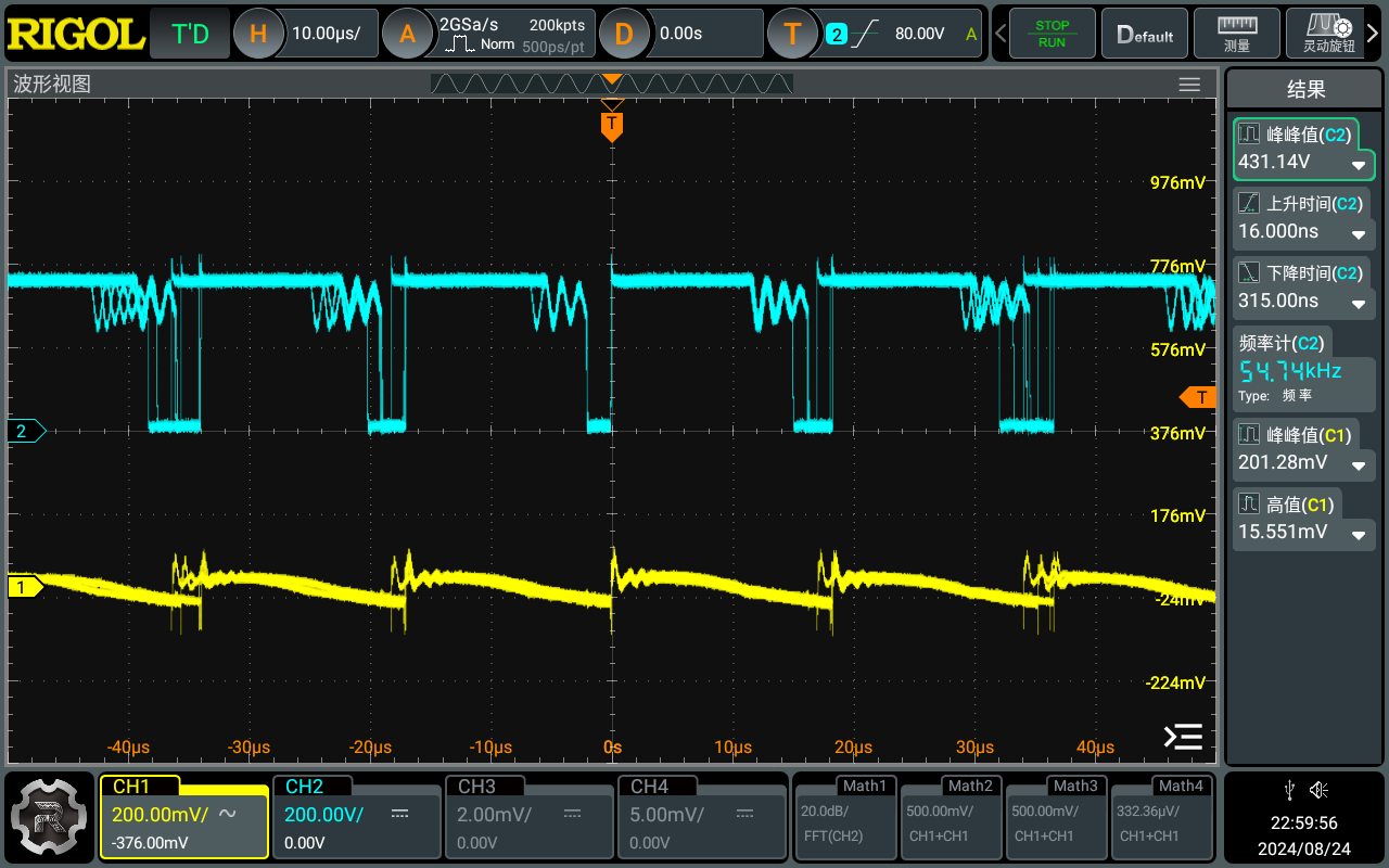
12V test, current 1-3A.


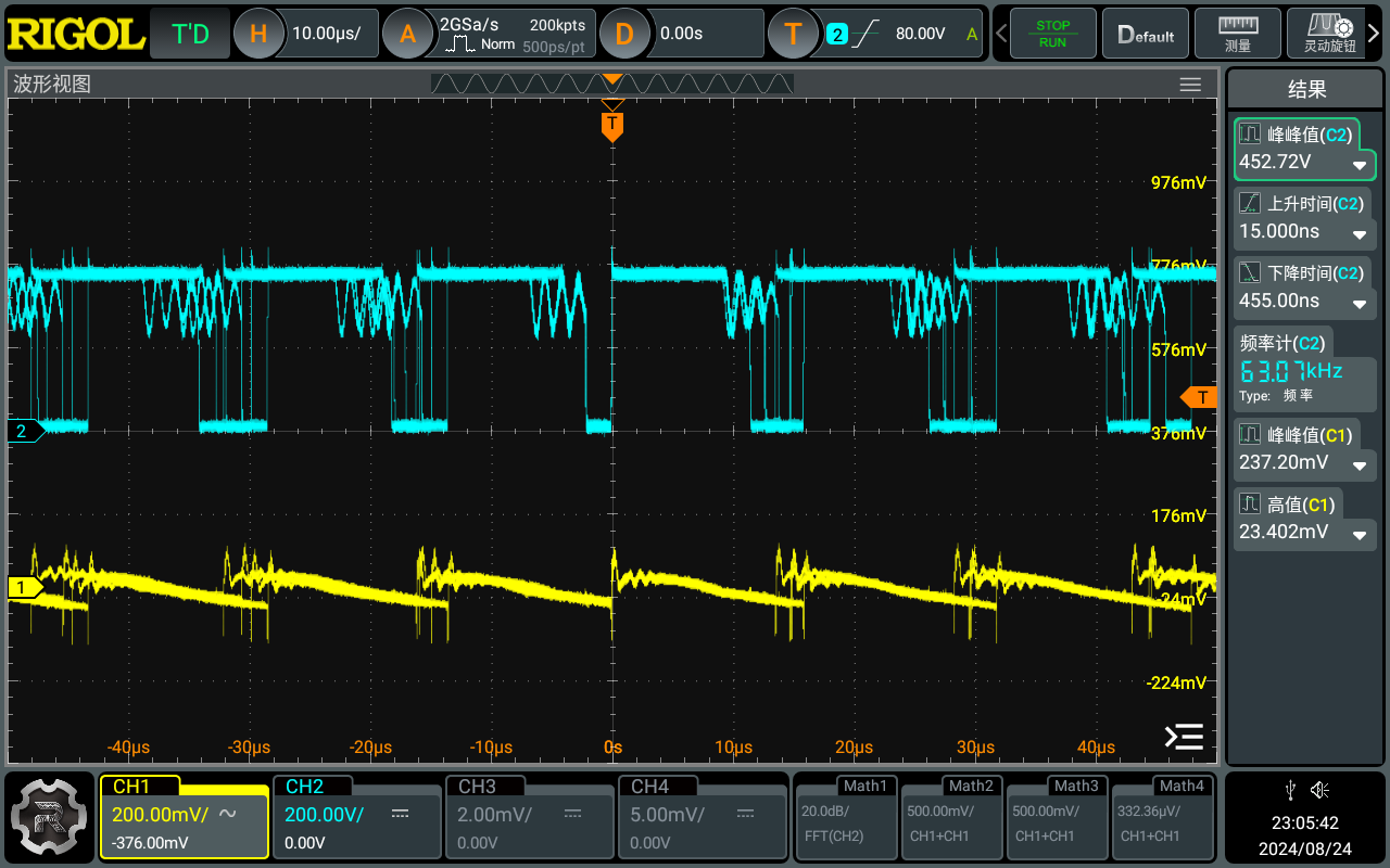
15V test, current 1-3A;


20V test, current 1-3.25A.


Test data summary:

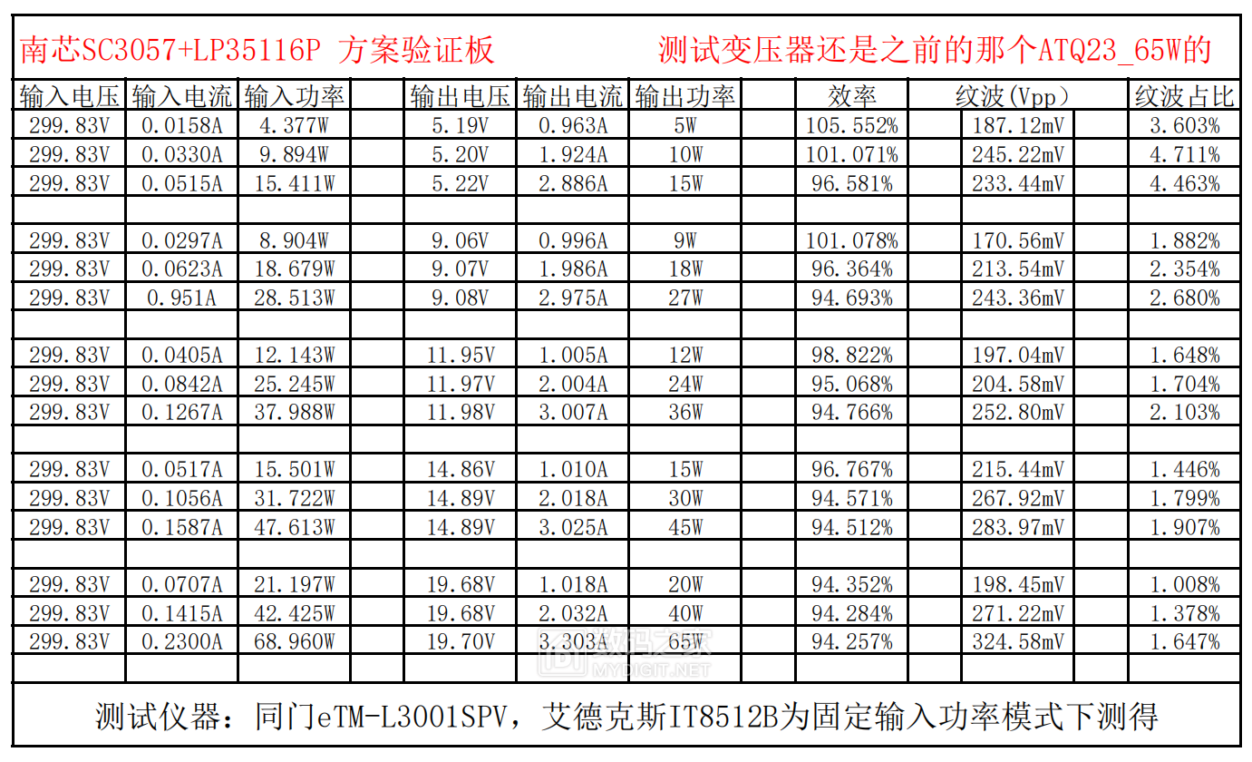
I have doubts about the efficiency of 5V 1A, but the data remained unchanged after restarting the instrument.
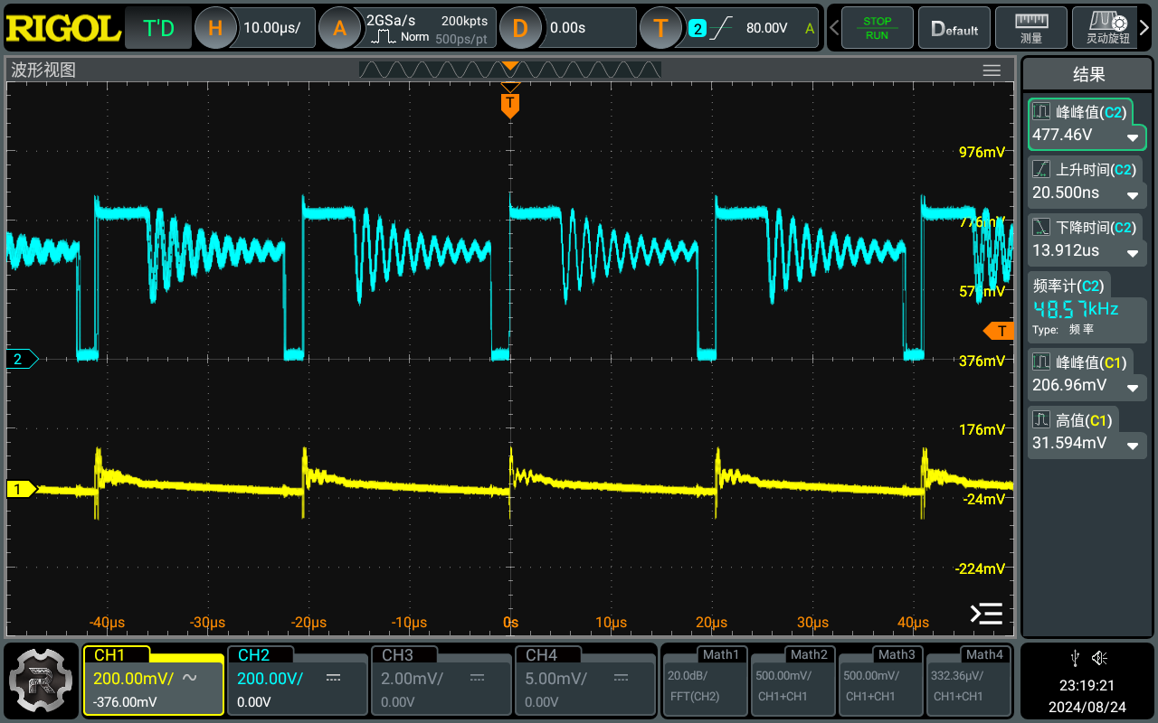
Two-hour full-load stress test:

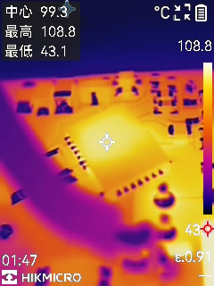
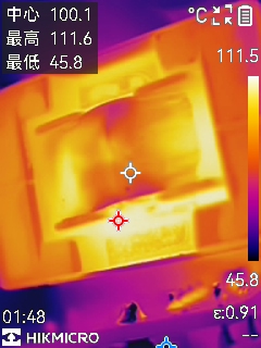
Thanks to the low internal resistance, the chip's stability is not very high.


 京公网安备 11010802033920号

 FSTU16861


