I. Design Background
An ADC (Analog-to-Digital Converter) is an indispensable key component in electronic systems. It converts continuous analog signals into digital signals, enabling digital processing and analysis. ADCs play a crucial role in signal conversion, measurement and data acquisition, control system input, and communication and signal processing. Their widespread application promotes the intelligent and precise control of electronic equipment across various industries, and is one of the key factors driving modern technological progress. A digital voltmeter and ammeter combines ADC technology with circuit measurement principles, accurately converting analog voltage and current signals into digital displays for easy reading and analysis by electronic engineers. This device not only improves the accuracy and efficiency of circuit measurements but also helps engineers better understand circuit behavior, serving as a powerful tool for electronic design and troubleshooting, and playing a vital supporting role in the work of electronic engineers. In product applications, digital voltmeters ensure the accuracy and safety of circuit design, while also providing strong support for product quality control and subsequent maintenance.
Learning to design and build a digital voltmeter and ammeter is highly beneficial for improving one's professional skills. This digital voltmeter and ammeter project covers multiple aspects, including microcontroller circuit design and implementation, signal acquisition and processing circuit design, user interface development and optimization, and product appearance design. It integrates knowledge from multiple fields such as electronics, microcontroller programming, circuit design, and industrial design. Considering the learning pace and knowledge absorption capacity of beginners, we have specially launched this introductory-level digital voltmeter and ammeter project, which is very suitable for beginners in electronics and those who want to learn more about microcontroller applications. This project has the following highlights:
it adopts a core board plus expansion board design concept and uses plug-in components, making learning simpler and exploration more in-depth;
the core board uses the domestic Wuhan Xinyuan Semiconductor CW32 as the main controller, while also being compatible with other similar development boards; however, the CW32 has advantages.
The project is highly comprehensive and practical, and after completion, it can be used as a desktop instrument;
the project has abundant learning materials, including circuit design tutorials, PCB design, code programming learning, and training for engineers' debugging skills.
II. Hardware Design
1. Power Supply Circuit
This project uses an LDO as the power supply. The actual maximum voltage used is within 24V, so a 78L05 was selected as the power regulator. On the one hand, it avoids the ripple interference of the DC-DC buck circuit, and on the other hand, it simplifies the circuit and reduces costs.

2. MCU Selection
This project uses the LCSC CW32F030C8Tx development board (core board) as the main controller.
The important advantages of CW32 in this project
are: wide operating temperature range: -40~105℃;
wide operating voltage range: 1.65V~5.5V (STM32 only supports 3.3V system);
strong anti-interference: HBM ESD 8KV; all ESD reliability reaches the highest level of international standards (STM32 ESD 2KV);
key features of this project - better ADC: 12-bit high-speed ADC can reach ±1.0LSB INL 11.3ENOB; multiple Vref reference voltages... (STM32 only supports VDD=Vref);
stable and reliable eFLASH technology.
The main characteristics of the CW32 ADC: This project requires a focus on the 4 reference voltage sources. (Content from the "CW32x030 User Manual")

3. Voltage Sampling Circuit:
The voltage divider resistors in this project are designed to be 220K+10K, therefore the voltage division ratio is 22:1 (ADC_IN11).
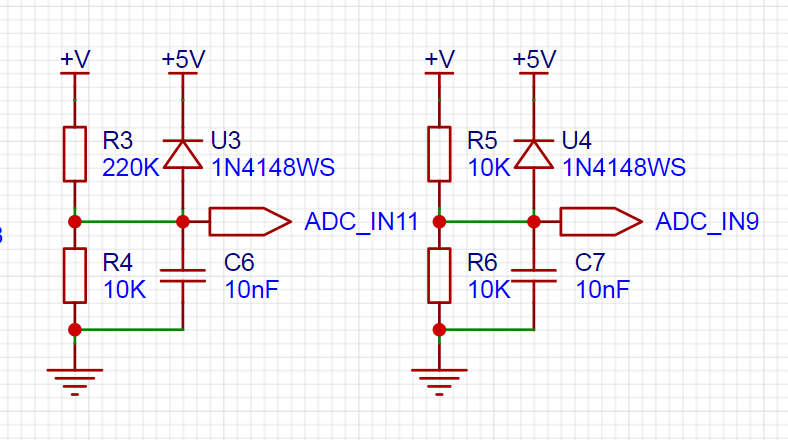
The voltage divider resistor selection
is designed to measure the maximum voltage. For safety reasons, this project uses 30V (the actual maximum display value can be 99.9V or 100V).
The ADC reference voltage is 1.5V in this project, and this reference voltage can be configured through the program.
To reduce the power consumption of the sampling circuit, the low-side resistor (R4) is usually chosen as 10K based on experience.
Then, the high-side resistance of the voltage divider resistor can be calculated using the above parameters.
The required voltage division ratio is calculated, i.e., the ADC reference voltage. The input voltage is designed; using known parameters, 1.5V/30V = 0.05 can be calculated.
The high-side resistance is calculated as the low-side resistance/voltage division ratio; using known parameters, 10K/0.05 = 200K can be calculated.
A standard resistor is selected: a resistor slightly higher than the calculated value of 200K is chosen. We usually choose E24 series resistors; therefore, in this project, 220K, which is greater than 200K and closest to the calculated value, is selected.
If, in actual use, the voltage to be measured is lower than 2/3 of the module's design voltage (66V), the voltage divider resistor can be replaced and the program modified to improve measurement accuracy. The following example illustrates this:
Assuming the measured voltage is no higher than 24V and other parameters remain unchanged,
calculations show 1.5V/24V = 0.0625, 10K/0.0625 = 160K. 160K is a standard E24 resistor and can be directly selected, or a higher value 180K can be chosen with some redundancy.
If, in actual use, the voltage to be measured is higher than the module's 99V design voltage, a different resistor can be selected. To achieve a wider voltage measurement range, one can choose to replace the voltage divider resistor or modify the reference voltage. The following example illustrates this:
Assuming the measured voltage is 160V, the solution is to increase the voltage reference to expand the range.
Given that the voltage division ratio of the selected resistor is 0.0145, we can calculate 160V * 0.0145 = 2.32V using the formula. Therefore, we can choose a 2.5V voltage reference to expand the range (increasing the range will reduce accuracy).
Considering the potential fluctuations in the measured power supply, a 10nF filter capacitor is connected in parallel with the low-side voltage divider resistor to improve measurement stability.
Range switching:
In this project, an additional voltage sampling circuit was added. Therefore, we can discuss the significance of range switching for improving measurement accuracy. Multimeters often have multiple range settings for more accurate measurements. By adjusting different ranges, the optimal measurement accuracy of the measured point within the corresponding range can be obtained.
This project requires a combination of hardware and software to achieve this function. When we first use the ADC_IN11 channel mentioned earlier to measure voltages below 30V... If the measured voltage is within 0~3V, the ADC_IN9 channel is used for measurement. At this time, due to the reduced voltage division ratio, the measurement accuracy is greatly improved. There are many ways to implement gear shifting, and the development board design provides more design possibilities.
4. Current Sampling Circuit
This project uses a low-side current sampling circuit for current detection. The low-side of the sampling circuit shares a common ground with the development board's meter interface.

Design Analysis
The sampling current designed for this project is 3A, and the selected sampling resistor (R10) is 100mΩ. The sampling selection mainly needs to consider the following aspects: the maximum value of the pre-designed measurement current, the voltage difference caused by the 3A current sensing resistor
in this project , and generally not recommended to exceed 0.5V . The power consumption of the current sensing resistor should be selected according to this parameter. Considering the power consumption (temperature) problem under high current, a 2W surface-mount current sampling resistor was selected. The amplification factor of the voltage across the current sensing resistor: No operational amplifier is used to build the amplification circuit in this project, therefore the amplification factor is 1.
The current sensing resistor value can then be calculated using the above parameters.
Since this project does not use an amplifier circuit, a larger sampling resistor is needed to obtain a higher measured voltage for measurement.
Considering that a larger resistor would result in a larger voltage drop and higher power consumption, an unlimited selection of a larger resistor is not possible.
This project uses a 2W package resistor, corresponding to a 2W power rise.
Based on the above data, a 100mΩ current sensing resistor was chosen. According to the formula, 3A * 100mΩ = 300mV, 900mW.
To handle different operating environments, especially high-current scenarios, the R10 resistor can be replaced with constantan wire or a shunt. The appropriate alternative can be chosen based on the specific application scenario. For safety and educational purposes, this project does not discuss measurements exceeding 3A, but the principle remains the same.
5. Digital Tube Display:
This project uses digital tubes as the display unit.

Two 0.36-inch three-digit common-cathode digital tubes are used as display devices. Compared to a display screen, digital tubes have better visibility in complex environments, better mechanical properties, and are less prone to damage. The current-limiting resistor diagram for the digital tube is convenient to design in-place. (R1~R6) is 300Ω, and the required drive current is 3.3V ÷ 300Ω ≈ 11mA, which does not exceed the drive current of the I/O port.
6. LED Indicator
This project designed an I/O working indicator for international case studies: lighting.

7. Button Circuit Design
This project uses 3 tactile switches for mode switching, calibration, and exit of the voltmeter and ammeter.

There are multiple design methods for the button control circuit. Thanks to the fact that the CW32's I/O port can be configured with pull-up and pull-down resistors internally, the button control circuit on the outside of the chip does not need to be configured. One end of the button is connected to the MCU's I/O, and the other end is grounded. When the button is pressed, the I/O is pulled low.
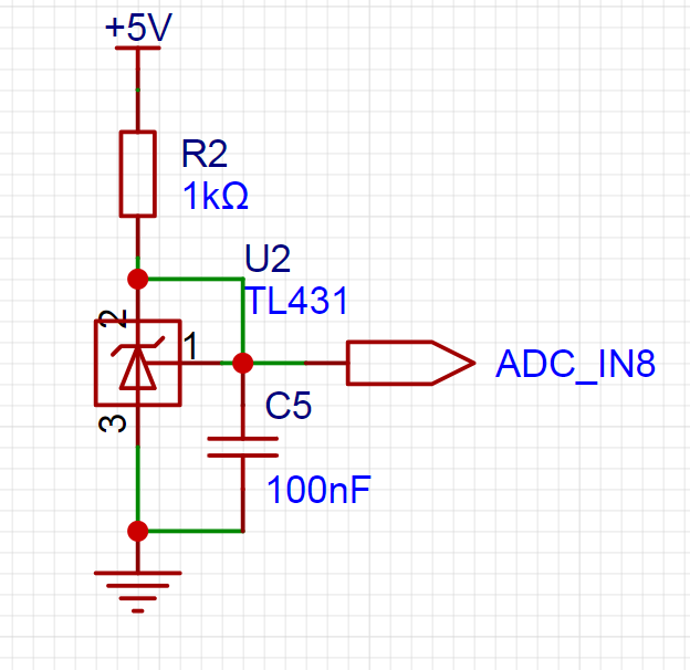
8. TL431 Circuit Design for Voltage Measurement Calibration
This project added an additional TL431 circuit to provide a 2.5V reference voltage, which can be used to provide an external voltage reference for the chip to calibrate the AD. From a product design perspective, due to the inherent ADC performance advantages of the CW32, this circuit is not necessary. This circuit was designed on the development board to learn the relevant application principles.
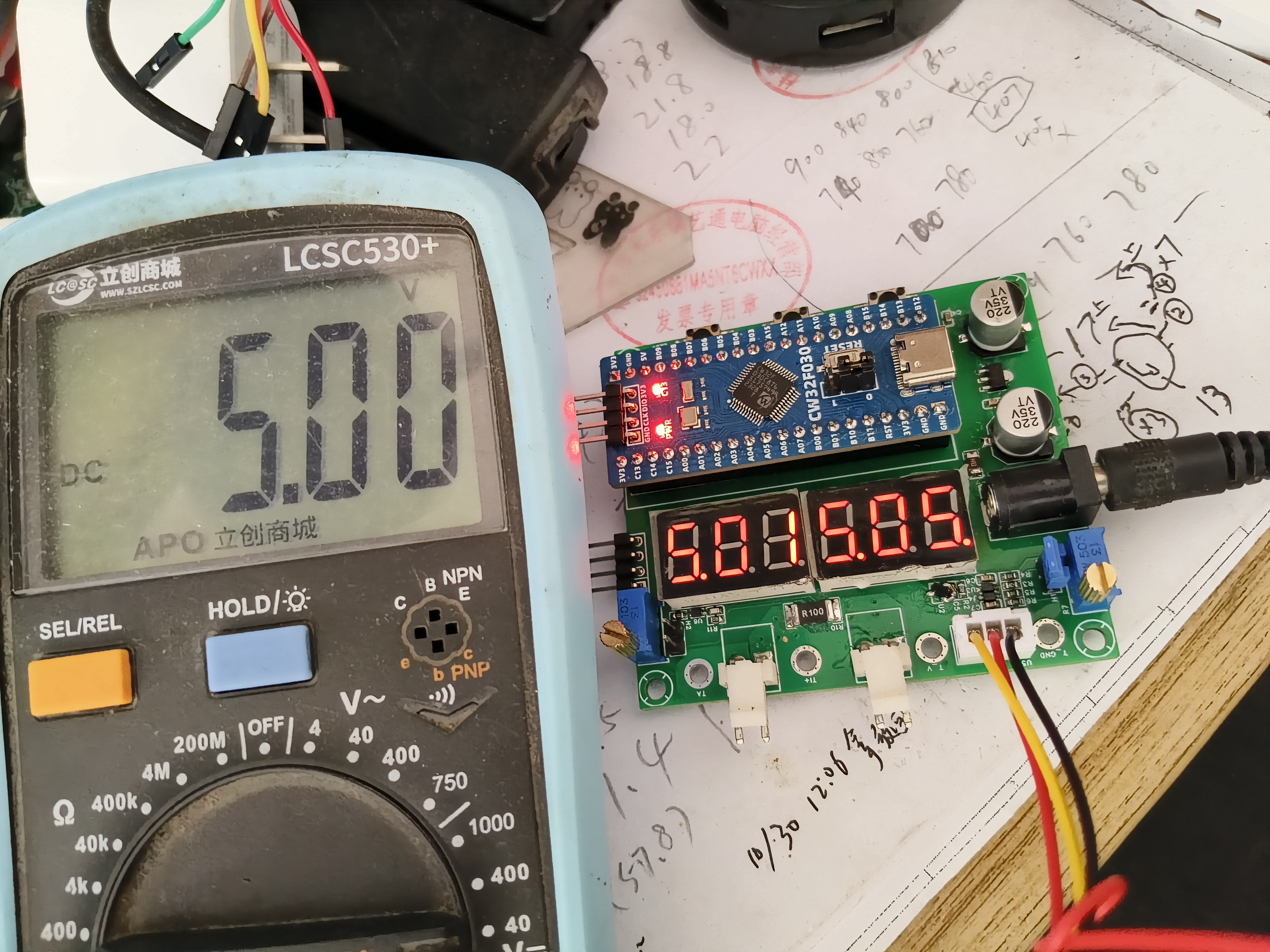
III. Project Demonstration:
Due to carelessness in reversing the vertical direction of the digital tube, the circuit board was rotated 180 degrees for use.
1. Voltage Calibration Process:
Calibrate 5V,
calibrate 15V.

2.
Measurement After Calibration: Before calibration, the multimeter showed 5.03V at
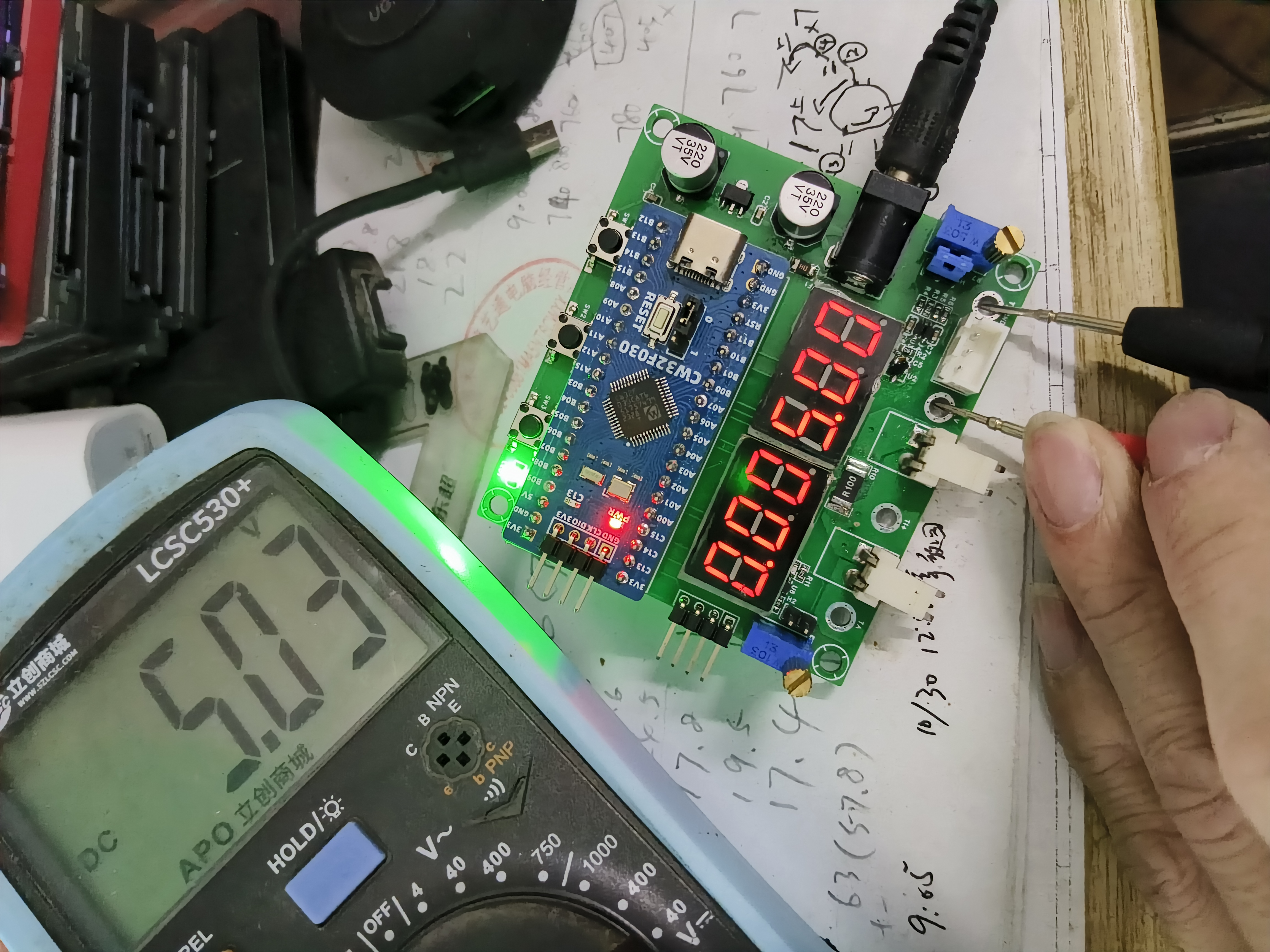
5V .

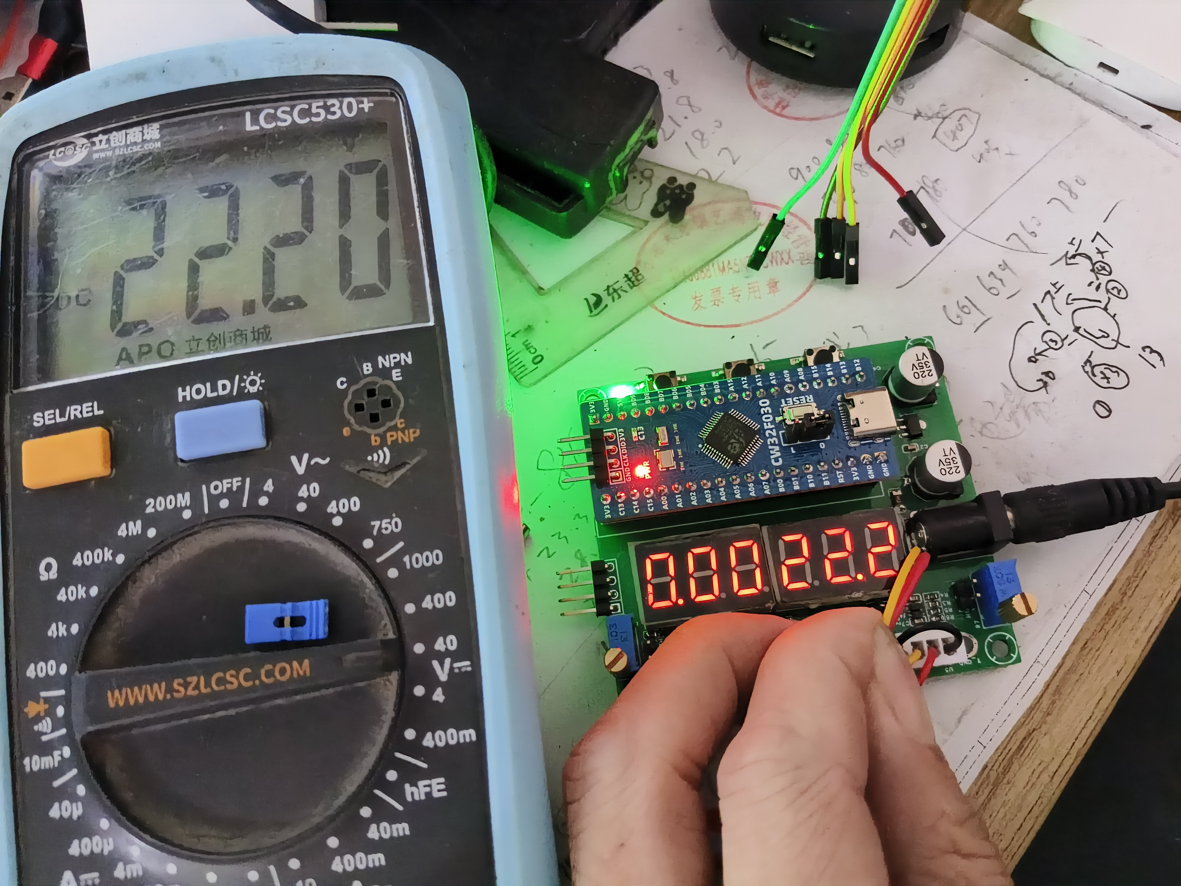
After calibration, the battery voltage was measured at
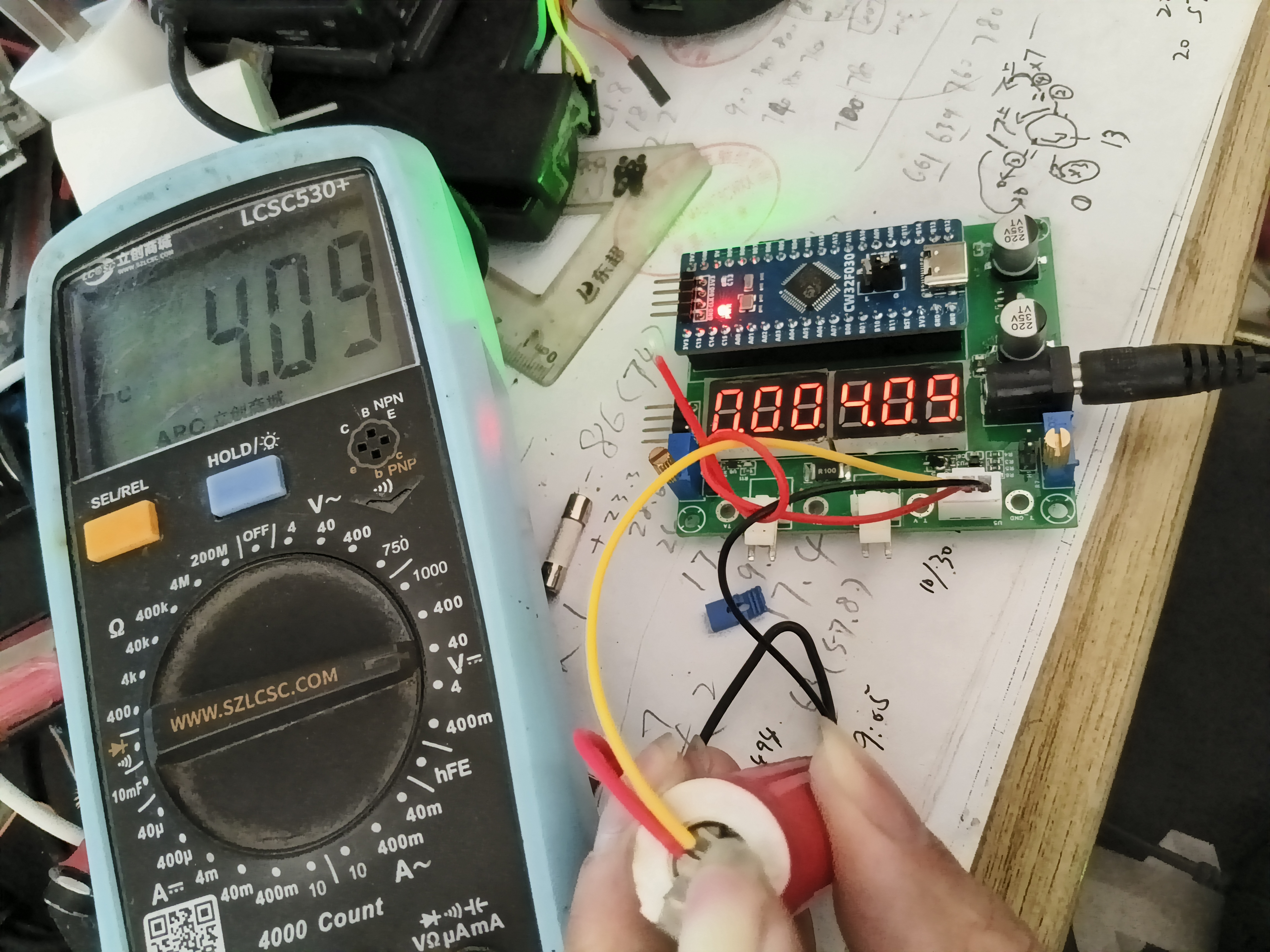
+V. The yellow wire was used to directly measure the 22V power input.
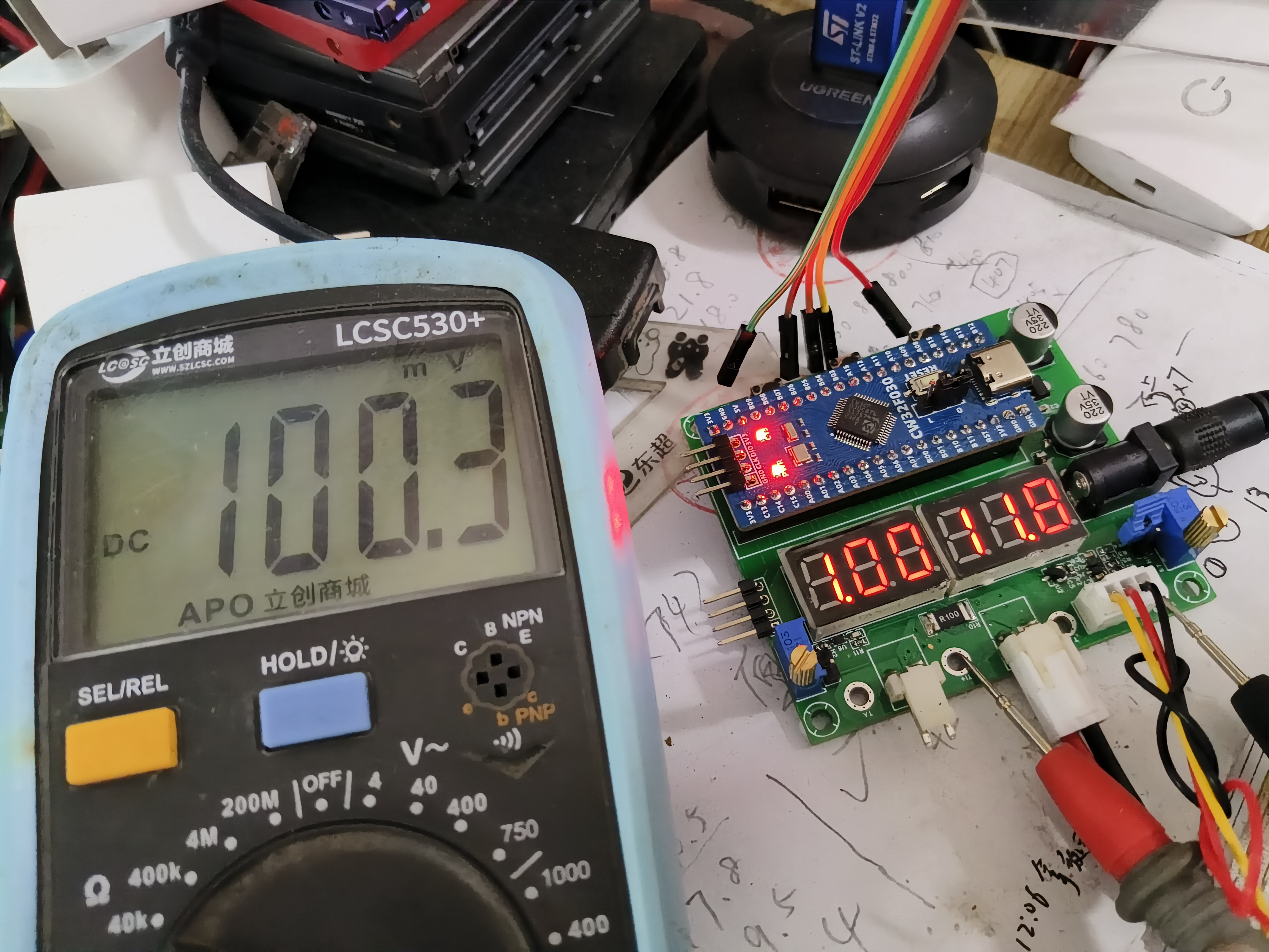
Current measurement: 1A. The multimeter measured the voltage across the sampling resistor at 100.3mV. The power adapter input voltage was 11.8V
at 0.25A. The multimeter measured the voltage across the sampling resistor at 25.2mV.
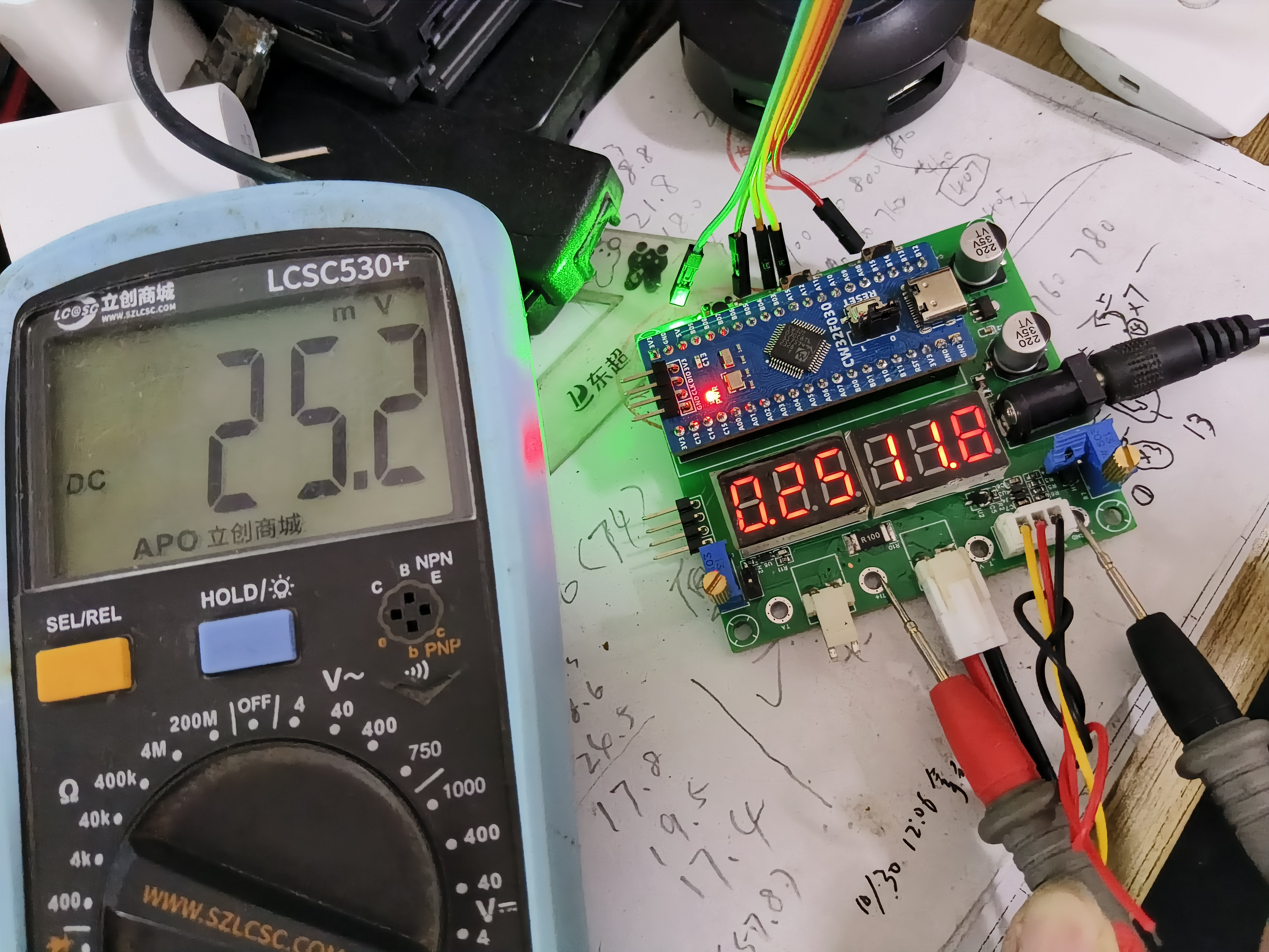
No suitable current measuring instrument was available, and current calibration was not performed, so the error is still slightly large. It's unclear if it's due to resistance error, but the error value is still within acceptable range. (The fuse on the LCSC multimeter's current setting was blown and not replaced.)
Thank you LCSC for providing such a great training camp and so many affordable development boards!


 京公网安备 11010802033920号

 S-812C54AY-X


