Video Link:
Bilibili Video -- Function Demonstration and
Project Introduction
This project uses the LCSC CW32F030C8T6 development board to design a voltage and current acquisition module. It supports 0-30V, ±5V, and ±1.5V voltage measurement, and two-channel ±1A current measurement. Data can be displayed via a serial port to a host computer, and an LCD display port is added to display the measurement data.
Project Functionality
This design is based on a voltage and current acquisition module designed using the LCSC CW32F030C8T6 development board. Utilizing operational amplifiers such as TL082 and TLV2372, it supports 0-30V, ±5V, and ±1.5V voltage measurement, and two-channel ±1A current measurement; data can be displayed via a serial port to a host computer or an LCD display.
Project Parameters:
This design utilizes the LCSC CW32F030C8T6 development board;
it employs TL082T and LV2372 operational amplifiers as the ADC preamplifier;
and it uses TP7660H chips to generate a -5V voltage to power the operational amplifiers, enabling negative voltage and current measurements.
This design references official examples and adds ADC protection.
Principle Analysis (Hardware Description):
This project consists of the following parts: power supply, voltage acquisition, current acquisition, serial communication, and LCD display. The main function of this project is to acquire current and voltage signals.
First, the power supply uses Type-C. Diode protection is not included because the supply voltage is 5V, and the voltage drop would be insufficient for the operational amplifiers. Two TP7660H chips generate a negative voltage to power the operational amplifiers, which, when connected to the development board, provides a 3.3V power supply to the LCD display and the CH340C serial communication chip. Partial circuit diagrams are shown below.

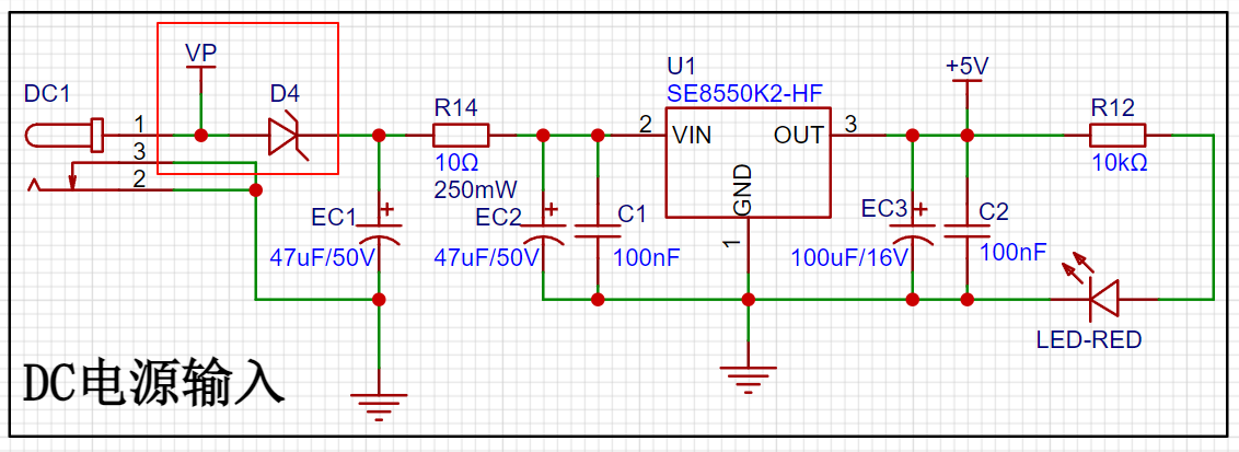
Figure 1 – Power Supply Circuit:
A TYPE-C-16P interface is used as the power supply interface, and the corresponding USB data pins are connected to the corresponding USB pins (USBD+) and (USBD-) of the CH340. 5.1K pull-down resistors are added to the CC1 and CC2 pins for easy identification and configuration by different host devices. Two TP7660H chips are used to generate negative voltage to power the operational amplifier.
Next is the voltage acquisition circuit. The 0-30V voltage acquisition voltage is based on the official engineering case. Automatic range switching is available for 0-3V voltage measurement to perform low-voltage measurements. For ±5V and ±1.5V voltage measurements, a TL082 is used as the ADC preamplifier, with an operational amplifier used as a voltage follower for impedance matching. The signal is then attenuated and DC biased through an inverting circuit. As shown in the following figures:
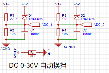
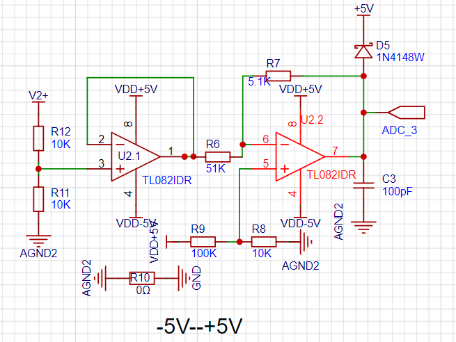

Figure 2 - Voltage Acquisition Circuit.
The current acquisition circuit uses a 50mΩ sampling resistor. The voltage of the sampling resistor is acquired through a TLV2372 differential input to measure the current, allowing for the measurement of two current data streams. A bias is provided through a TL082 to measure negative currents. The circuit is shown below, theoretically capable of measuring a current range of ±1A.
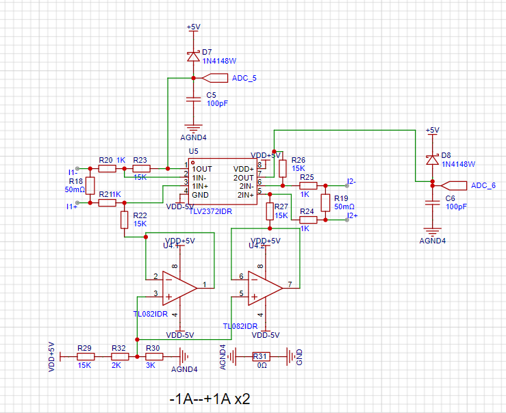
Figure 3 - Current Acquisition
Circuit. Serial communication samples the CH340C chip. Due to integration issues with the development board, one-click serial download is not currently supported. The screen interface supports the 12-pin SPI protocol. FPC terminals are designed for wiring. The circuit diagram is shown below:

Figure 4 - LCD Display Circuit.
The software code
uses ADC+DMA for verification via serial port. The LCD display screen has not yet been verified due to time constraints. The circuit has been verified without problems in other projects.
LabVIEW host computer
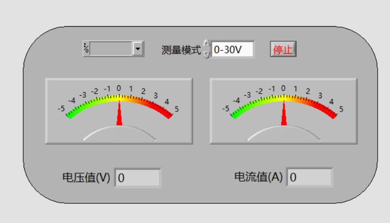
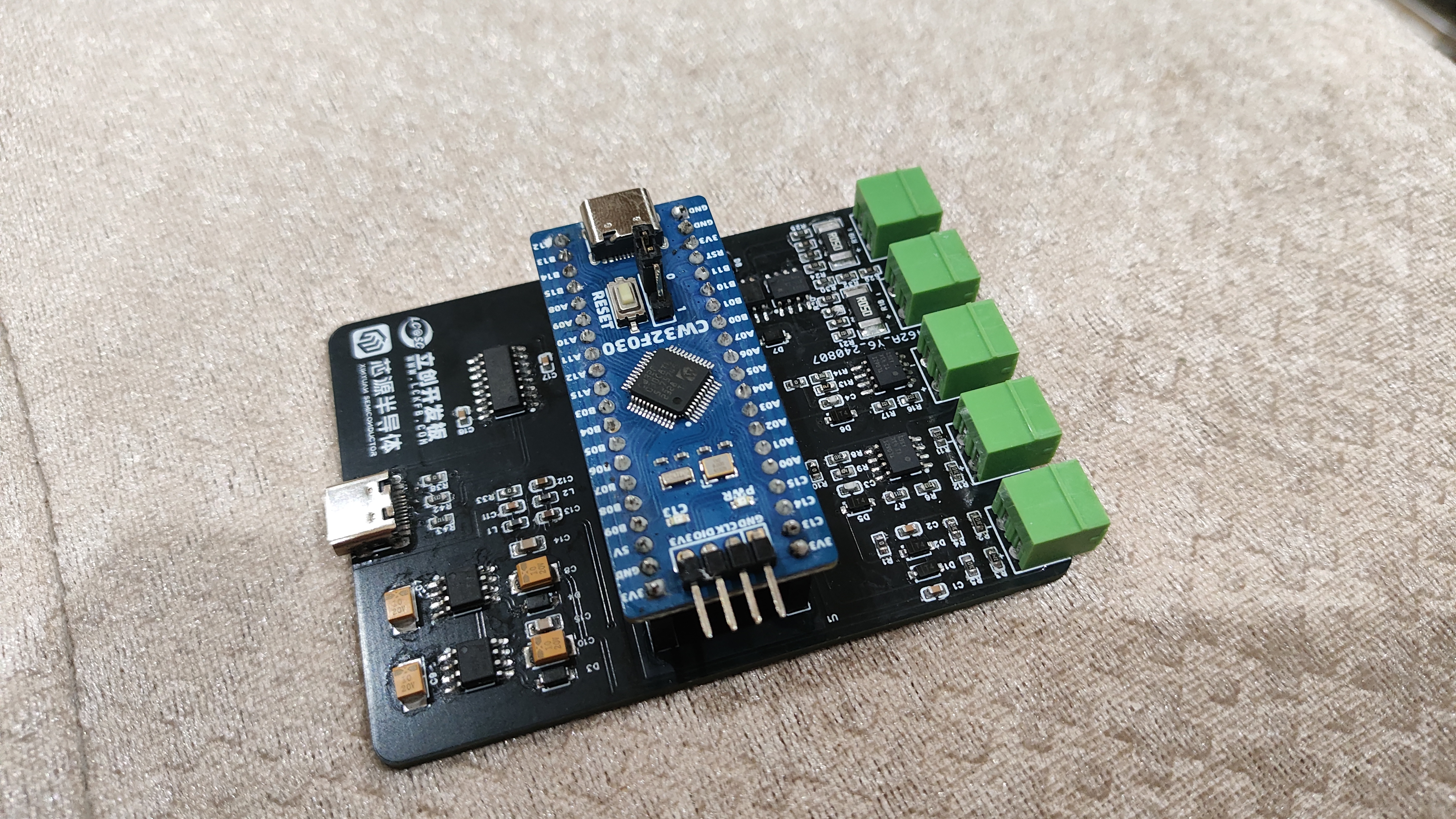
physical diagram .
Complete physical diagram.
PDF_Voltage and Current Acquisition Module.zip
Altium Voltage and Current Acquisition Module.zip
PADS_Voltage and Current Acquisition Module.zip
BOM_Voltage and Current Acquisition Module.xlsx
92725
Voltage and Ammeter Training Camp - Mu Yueguang - 07/16
LCSC Voltmeter and Ammeter Training Camp:
Official Template Replica
I. Function Introduction
1. Voltage Measurement
Range: 0~34.5V (Theoretical Value)
2. Current Measurement
Range: 0~3A
Since the current sampling resistor is 0.1Ω/1W, according to the power formula P = I^2 * R; I ≈ 3.3333; rounded down, the measurement range is 0~3A.
3. Button Functions
From left to right, these are K1, K2, and K3 buttons.
K1 Function: Cycles through the interface.
K2 Function: Saves calibration values; calibrates voltage and current and saves calibration values during the calibration interface.
K3 Function: Returns to the voltage and current measurement interface.
4.
When pressing K1, the upper digital display will show either the calibration voltage or current, and the calibrated voltage and current values.
The lower digital display will show the currently measured voltage or current value.
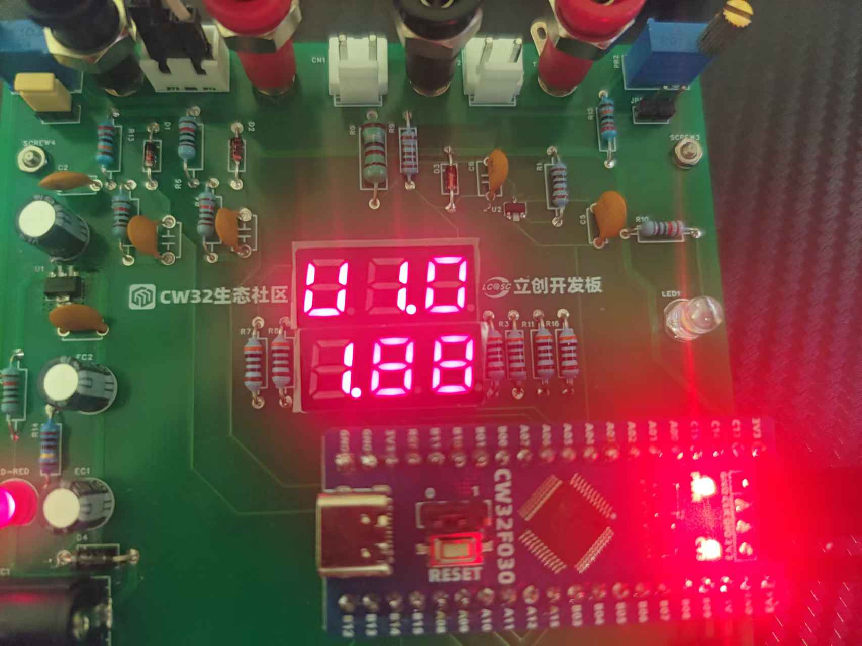
U represents the calibration voltage. 1.0 indicates the current calibration voltage is 1.0V.
1.88 indicates the current measured voltage is 1.88V.
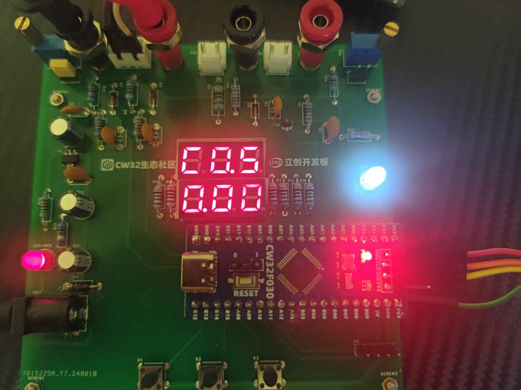
C represents the calibration current. 0.5 indicates the current calibration current is 0.5A.
0.00 indicates that the current measured current is 0A.
II. Hardware Introduction
Hardware selection can be referred to the official example program; for brevity, further details are omitted.
Difference from the official example program (improvement):
The power supply circuit VP network number is connected to the positive terminal of the switching diode.
III. Hardware Optimization
① A self-locking switch can be added to the power supply circuit, located after the network number VP and before the switching diode.
② The voltage and current measurement terminals can be replaced with rubber sockets (same as the external voltage and current verification interface).
③ The expansion board LED can be connected to another GPIO port (the core board LED is already connected to PC13).
Digital voltmeter and ammeter. 7z
PDF_Voltmeter and Ammeter Training Camp_Mu Yueguang_07-16.zip
Altium_Voltage and Ammeter Training Camp_Mu Riguang_07_16.zip
PADS_Voltage and Ammeter Training Camp_Mu Riguang_07_16.zip
BOM_Voltage and Ammeter Training Camp_Mu Yueguang_07_16.xlsx
92726
Based on the CW32 voltage and current meter of the [LCSC development board]
CW32 ammeter and voltmeter, measuring voltage 0~30V and current 0~1A. Battery powered.
This is a training project from the LCSC CW32 development board voltmeter and ammeter project, a digital voltmeter and ammeter built based on the LCSC CW32F030.
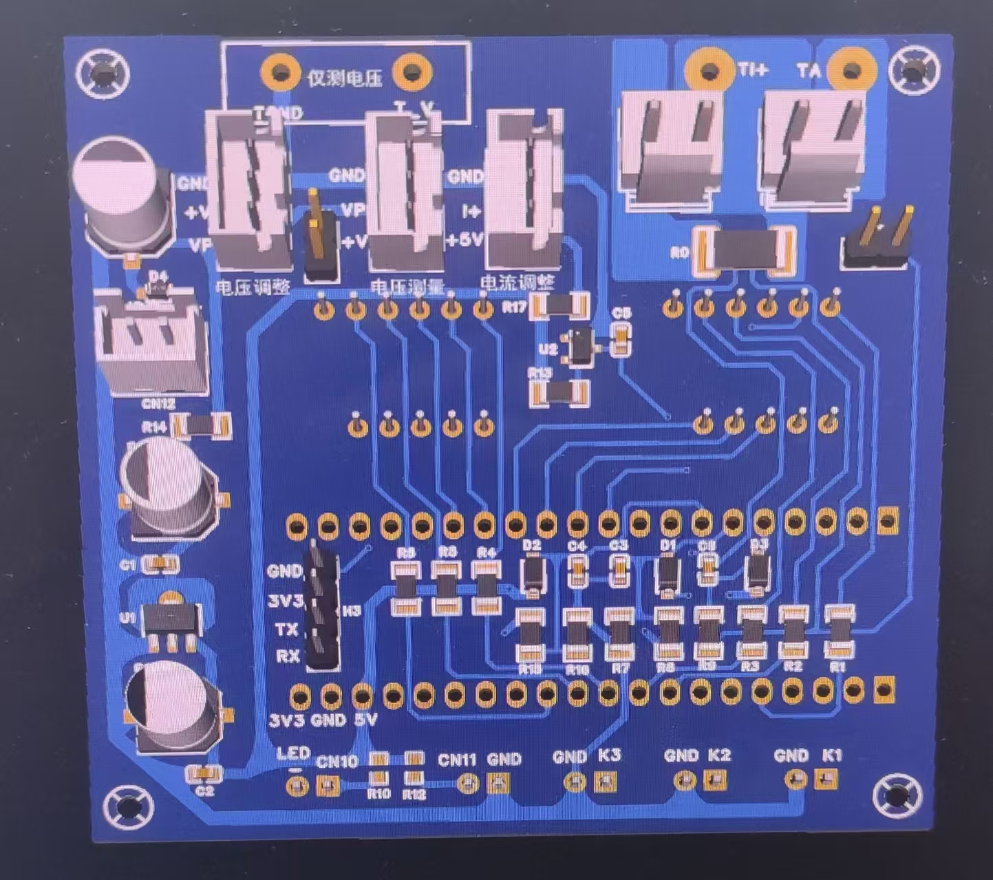
Circuit Design: To minimize the size of the main voltmeter, surface-mount components were used in the circuit board design.
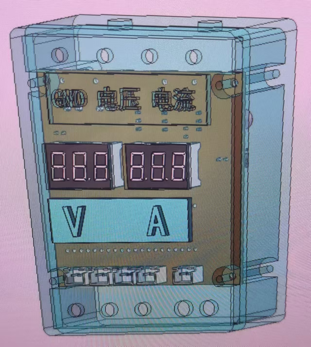
Case Design: The case was designed using SOLIDWORKS software. After assembly and verification, the model was exported as an STL file and printed using a 3D printer.
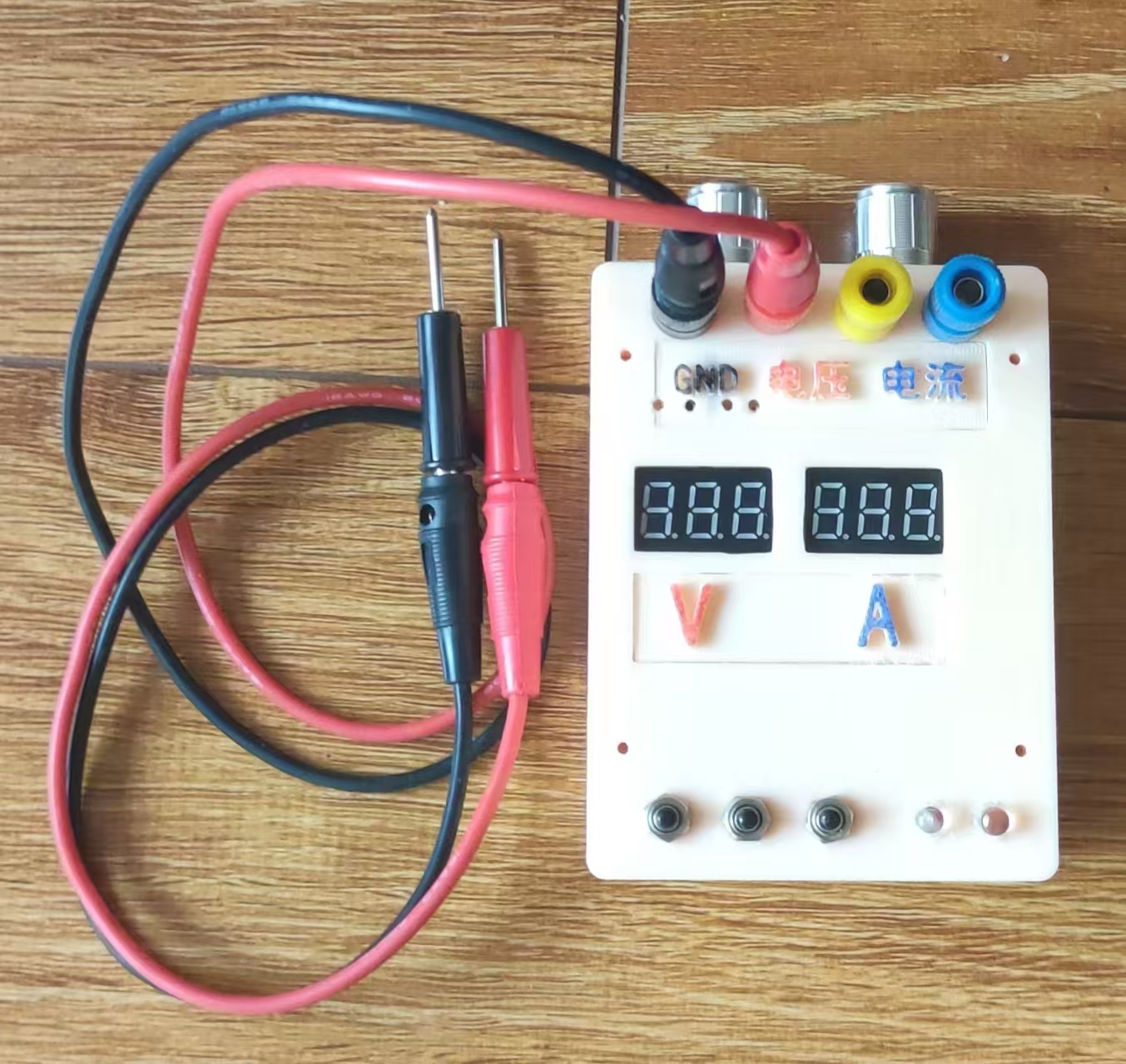
Finished Product Showcase:
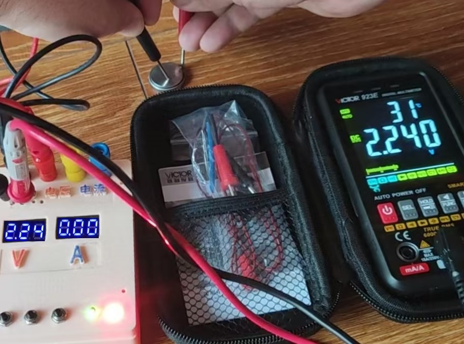
Product Testing: Voltage measurement was demonstrated using a 3V button battery.
CW32 Voltage and Current Meter.rar
shell.STL
Cover.STL
identifier.STL
Signage.STL
PDF_Based on the CW32 Voltage and Current Meter of [LCSC Development Board].zip
Altium_Based on the CW32 Voltage and Current Meter of [LCSC Development Board].zip
PADS_Based on the CW32 Voltage and Current Meter of [LCSC Development Board].zip
BOM_Based on the CW32 Voltage and Current Meter on the LCSC Development Board.xlsx
92728
electronic


 京公网安备 11010802033920号

 07-3153T200007


