1. A minimum system core board for MCUs compatible with various STM8S003F3P6 pin definitions.
2. Includes a DAPLINK interface modified from Liangshanpai DAPLINK.
3. Allows program download to 20-pin 003 series chips via USB Type-C interface.
4. Supports USB PD power supply, with PD protocol and can extract various voltages from the PD power supply.
5. The core board and LINK system have dual 5V and 3.3V power supplies, which can be selected or both can be output simultaneously. [Images:
Klipper can use resonance compensation modules, employing RP2040 and ADXL345.
The Klipper resonant compensation module
comes in two versions, using the RP2040 and ADXL345 connectors: one with a Type-C interface and the other with separate connectors. The flash memory used is also different. The smaller package version can be purchased cheaper on Taobao. A
modified printout of the Voron SB connector is included in the attachment.
The firmware and configuration file for the Klipper module with two 15.5mm hole pitches are also attached.

isky_sb_adxl_mount_generic_15.5mm_c_c.STL
klipper.uf2
adxl.cfg
PDF_klipper resonance compensation.zip
Altium_klipper resonance compensation.zip
PADS_klipper resonance compensation.zip
BOM_klipper resonance compensation.xlsx
96558
【Rachel】ESP32S3 Mini Game Console 0603 Modular Version
Based on the original Rachel by Forairaaaaa, modifications were made to change all 0402 components to 0603 components for easier soldering.
Forairaaaaa's original design is no longer publicly available; only the latest version using the ESP32S3 development board is available: https://oshwhub.com/eedadada/mason.
Forairaaaaa's Rachel project description:
Rachel
ESP32 mini game console, great feel
and retro, can't do anything (sad).
Project purpose: Cute. All
components are 0603, you can solder them on a teppanyaki grill.
Project link: https://github.com/Forairaaaaa/Rachel.
Video introduction: https://www.bilibili.com/video/BV1Ga4y1f7d3/.
For detailed information, please refer to the original project: https://oshwhub.com/eedadada/mason.
Regarding the shell design adapted for this version, unfortunately, Forairaaaaa's original project is no longer publicly available. I will modify it based on the current version provided by them when I have time. I will upload it later.
PDF_【Rachel】ESP32S3 Mini Game Console 0603 Module Version.zip
Altium_【Rachel】ESP32S3 Mini Game Console 0603 Module Version.zip
PADS_【Rachel】ESP32S3 Mini Game Console 0603 Module Version.zip
BOM_【Rachel】ESP32S3 Mini Game Console 0603 Module Version.xlsx
96559
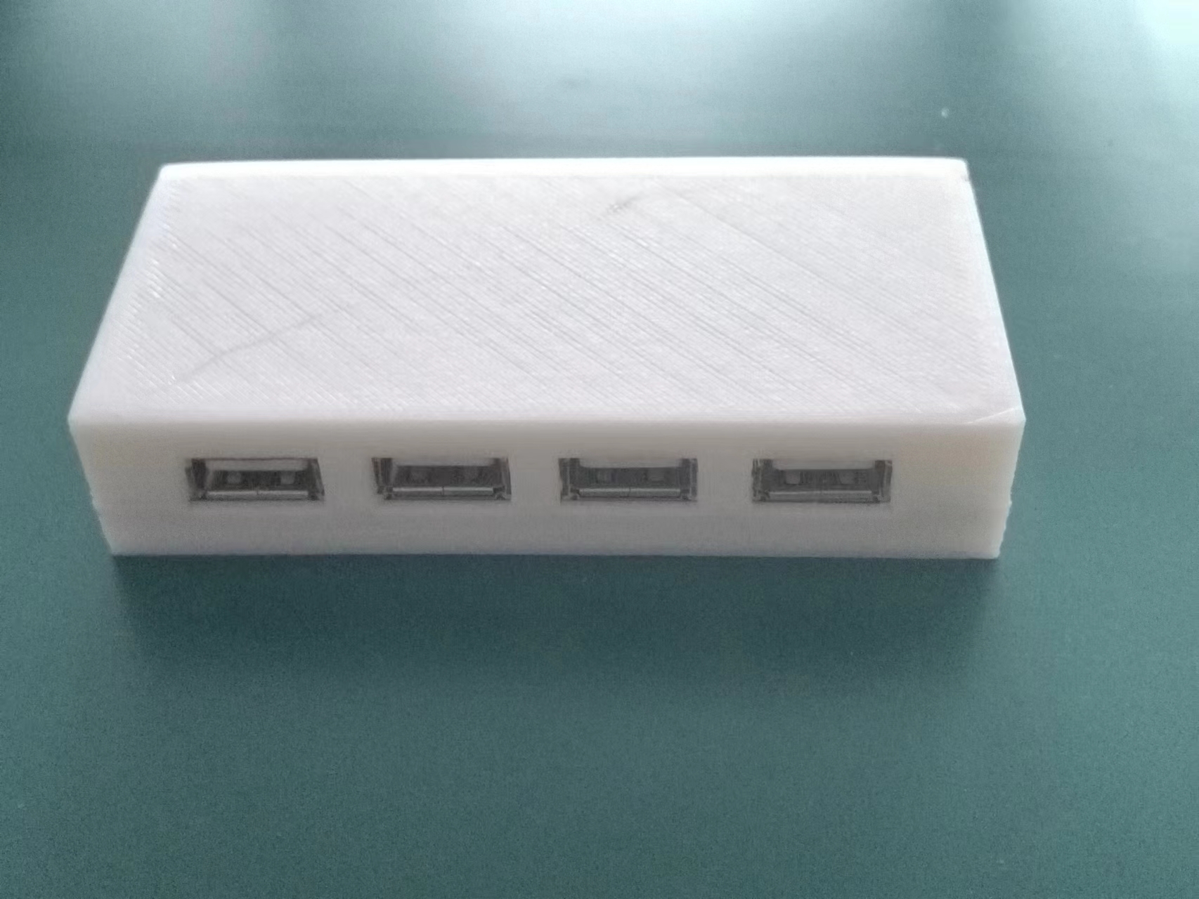
USB Hub Project 2
An exercise about USB 2.0 hubs
A USB 2.0 hub for USB expansion.
PDF_USB Hub Project 2.zip
Altium_USB Hub Project 2.zip
PADS_USB Hub Project 2.zip
BOM_USB Hub Project 2.xlsx
96560
A generic development board modeled after the official Nucleo board.
Among ST's boards, my favorite is the Nucleo board, but Nucleo boards are quite expensive. This time, I'm going to make a replica of the Nucleo-48 development board.
Important Notes Before Reading:
1. You are free to use this material for various projects, but it cannot be used for commercial purposes. In particular, the images in the illustrations are sourced from the "Official Railway Girls of China." Commercial use must comply with their regulations; unauthorized commercial use is prohibited (please respect copyright).
2. The automatically generated BOM may be incorrect; the specific BOM needs to be derived from the circuit diagram.
3. It is recommended that the maker be somewhat familiar with the circuit before starting to build, as soldering the LQFP-48 package is somewhat difficult. (The following appears to be unrelated and possibly machine-translated text: "
Completed board front
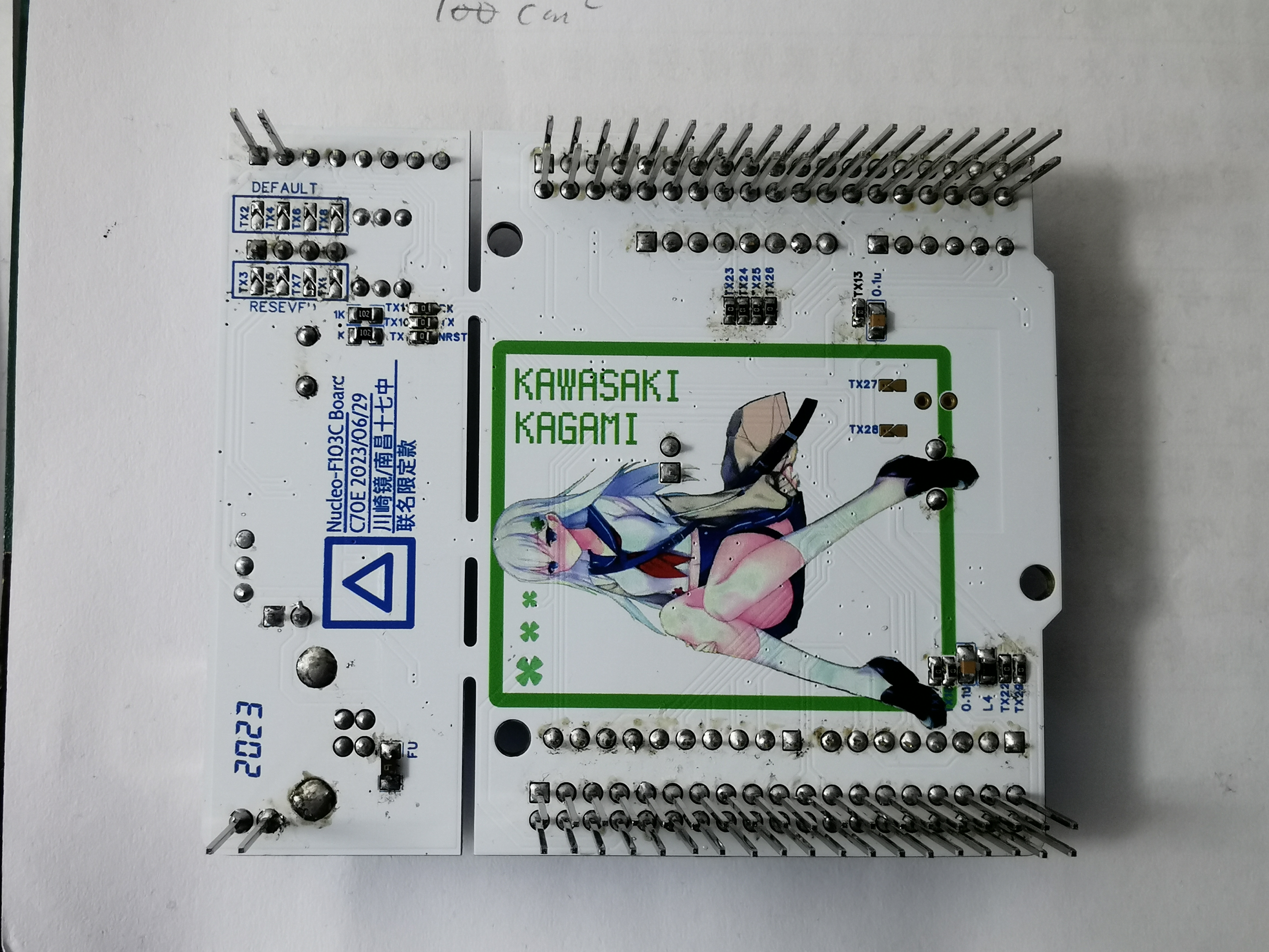
panel back panel
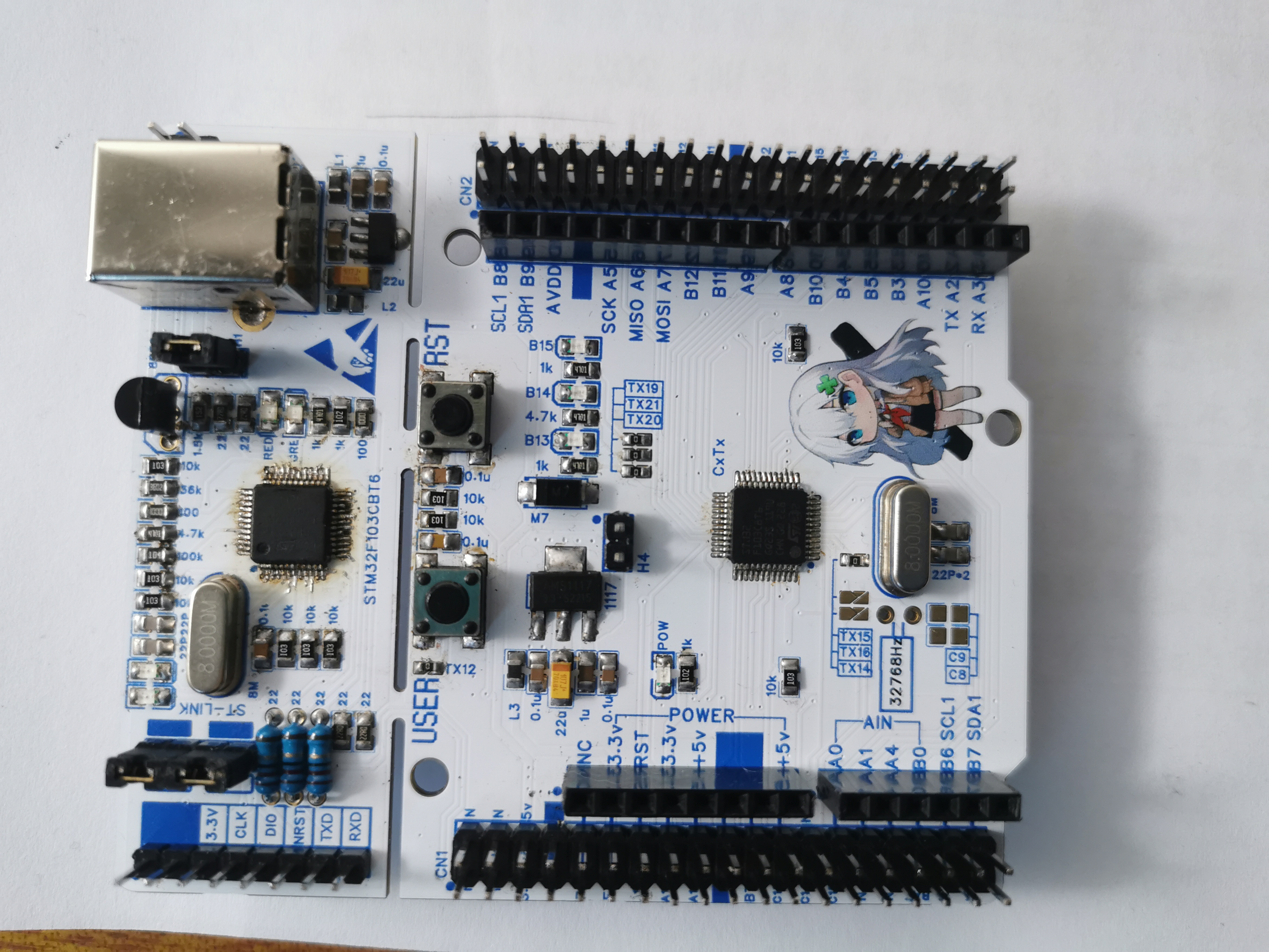
. Happy New Year everyone! This is C70E. I wish everyone a happy new year. Last year, I participated in JLCPCB's official color silkscreen printing activity. My work was a development board, and the reference design was STMicroelectronics' Nucleo-64 and Nucleo-48 templates.") To participate in this event, I asked my friends "Nanju Xiangduan HXD1B" and "Electric Bus K1019" for a towel featuring Kawasaki Kagami, a character from the Chinese anime "Railway Girls," along with her chibi-style image from the illustration book (after all, who doesn't love white stockings and white hair? (laughs)). Using my terrible Photoshop skills, I extracted the image and added it to the PCB.
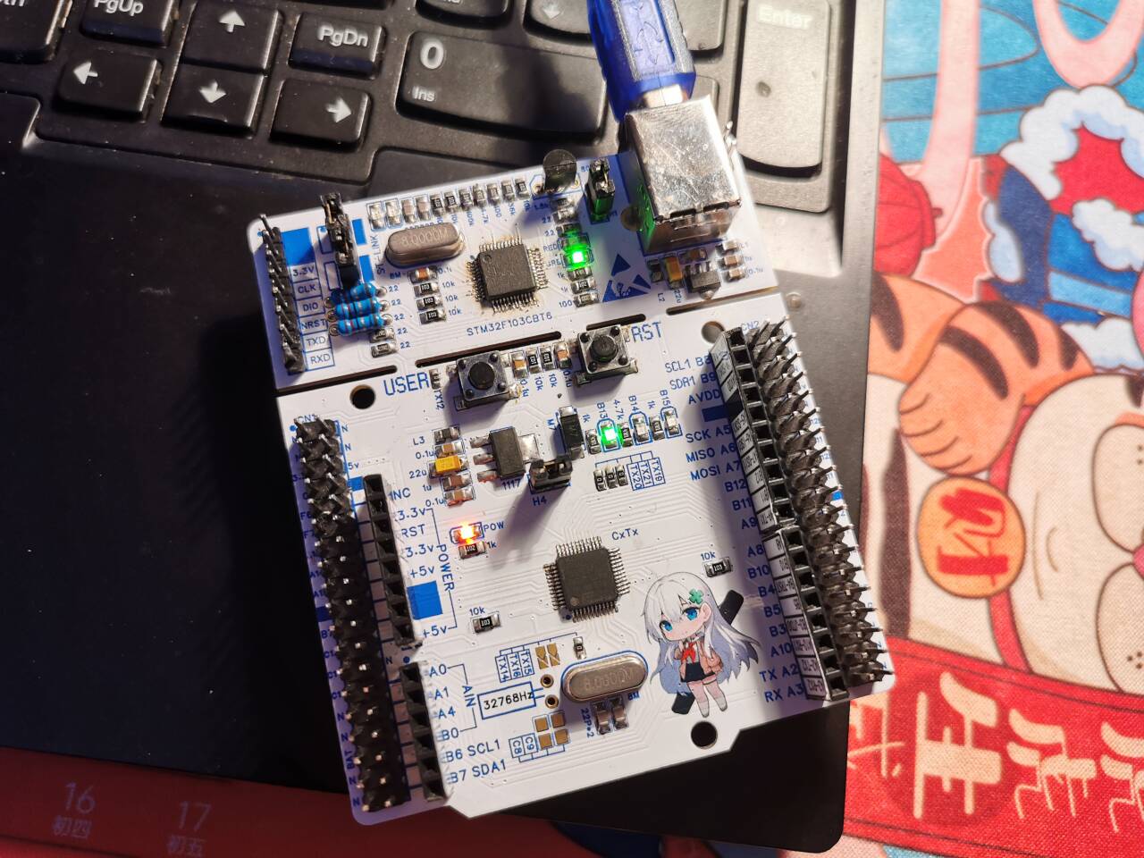
The board configuration consists of an ST-LINK V2-1 programmer and an STM32F103C8T6 minimum system. Peripherals include a button on pin PC13 of the microcontroller; and LEDs connected to ground on pins PB13, PB14, and PB15, which light up when high. All peripherals on the board can be enabled/disabled via shorting blocks, including the SWD interface, serial port, programmer, and programmer reset line. Compared to the original, I marked all the pins on the side of the board for easier use. The Arduino and ST interfaces are based on the Nucleo-F103RB, but the STM32F103RBT6 has many PC pins, while the C8 series does not. These missing PC pins are left unused, allowing for future shielding.


For ease of soldering, most components use 0805 packages, and the component layout is optimized for optimal performance. Since the board has a built-in programmer, firmware needs to be programmed before using the board. The firmware programming method is as follows:
1. Solder all components on both the board body and the programmer side, and connect the corresponding jumpers.
Refer to the circuit diagram for jumper details. 2. With TX3, TX5, TX7, and TX9 in the ON position and TX2, TX4, TX6, and TX8 in the OFF position, the programming pin sequence according to the schematic is 3.3V, CLK, GND, DIO. Connect the wires to another ST-LINKV2-1 in the correct sequence and power on. The computer should then detect the drive letter without any error messages.

3. Open the pre-installed STM32CubeProgrammer software, click the "open file" button, and load the ST-LINK V2-1 firmware to be downloaded; click the Connect button to connect to the target MCU; note that the chip capacity should be 128KB. If it's smaller than this, the ST-LINK V2-1 firmware cannot be flashed. This is to prevent purchasing incorrect or counterfeit chips. Then click the Download button and wait for the download progress to finish, displaying a successful download message.
4. Disconnect the ST-LINK used for downloading, and directly connect the Nucleo-48 Kawasaki Mirror with the firmware just flashed to the PC. Open the STM32CubeProgrammer software; you will see the "Firmware upgrade" button. Click to enter, then click the "Open in update mode" button. The chip will be detected; check the upgrade option, check the option to change the ST-LINK firmware, and check debug, mass storage, and VCP. Then click the update button and wait for the upgrade to finish.
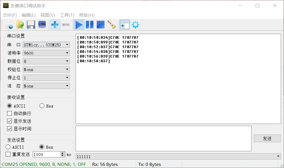
After successfully setting up the programmer, write a test program for LED lighting and serial port 2, and burn it into the microcontroller. If the program runs normally, you have succeeded. Make good use of this board; actually, this board does have some drawbacks. For example, after connecting the downloader to serial port 2 on the main body, it may not be possible to completely disconnect the power to the main body. If it's really inconvenient, you can disconnect the shorting block related to serial port 2 on the bottom. When you need to use serial port 2, you can directly use DuPont wires to fly wire.
Now let's talk about some trivial matters, about the activities and the artwork. Here, I want to give a thumbs up to the staff of JLCPCB. In the early stages of the board's completion, there was a via on the outside of the board frame that was not discovered. They called to inform us before manufacturing and also returned the voucher for color silkscreen printing after the order was cancelled. I only managed to get it fixed on the second prototype. I also want to apologize to them. I was busy with work at the end of the year, and although the board was completed a long time ago, the project was delayed. It was only uploaded today, but at least it's finally updated. Next, let me introduce the main character of the artwork, Kawasaki Kagami. She comes from a relatively obscure IP—"China Railway Girls." In a parallel world view, she is a developer of the CRH2A type EMU train, and she is also my favorite character in this IP. There are many related items for her, such as standees, cushions, towels, etc., but most of them aren't very practical, so I haven't bought any. For this event, however, I directly added her to this circuit board, making her and the board a practical item for me. I believe that no matter how late or tired I am while debugging, as long as I flip the board over, I can see her sitting behind it, smiling at me.
This concludes the board project; I hope you all liked it. I will also share other projects I've made later, so look forward to seeing you in the next one.
Here's a recommendation for my Bilibili video: https://www.bilibili.com/video/BV1Ec411D7v7. If you don't know how to burn files, you can check it out; it explains things in more detail than this article. Looking forward to your likes, comments, and shares!
[Schematic Diagram] Nucleo-F03C8.pdf
[Verified] [PCB Manufacturing File] Nucleo-F103C8.zip
[Other] Mother Labels.xlsx
[Test Program] Test-Nucleo-F103C8.ino.generic_stm32f103c.bin
【BOM】Nucleo-F103C8.xlsx
[LCSC Professional Edition Project Files] Nucleo-F103C8.zip
PDF_Replica of Nucleo's official universal development board.zip
Altium_Nucleo Official Universal Development Board.zip
PADS_A generic development board modeled after the official Nucleo website.zip
BOM_Replica of Nucleo's official general development board.xlsx
96561
ESP32S3 project
Enables device configuration and control via an app. It can communicate with large language models, such as Baidu's Wenxin Yiyan and language models provided by various GPT vendors. It also enables voice and infrared remote control of light on/off states.
This is a main control board similar to Tmall Genie, implemented using the ESP32S3. Currently, it's built using a modular assembly method. The main control board uses an ESP32S3 development board inserted into the verification board. Voice, amplifier, and SD card also use readily available modules, mainly saving time on hardware verification and directly verifying the software implementation. After stable verification, we plan to integrate them onto a single board later. The main functions implemented so far are as follows: 1. Human-computer dialogue based on a large language model. Press and hold the OK button, then speak. Releasing the button converts the speech to text, then requests a request from the backend to relay it to a third-party large language model. The returned text content is sent to the device, which then converts the text back to speech and plays it through the amplifier. Currently, it's integrated with Baidu Wenxin Yiyan for verification. Compared to GPT, Wenxin Yiyan is significantly inferior, but GPT has limited use in China and presents many problems. However, more other models, such as Microsoft Azure, will be integrated later. The integration model is configured in the backend, and model switching is transparent to the device. 2. Smart switch. The smart switch is the origin of my design for this board. Currently, it works with two other 8266 main control relay boards (one 86-in-one board and one micro single-control board, which will be open-sourced simultaneously) to achieve voice and infrared remote control of light on/off. During the initial configuration phase, an internet connection is required to configure the device. After the device is configured, all commands will be cached on the main control board, and then it can control other devices offline. 3. A touch screen will be added later to achieve more functions. 4. The ultimate goal is to achieve complete backend programming of the device using a server-side language like Java.
Soldering:
1. Two ESP32S3 development boards are configured on the board to support insertion on both the top and bottom of the board. Only one board needs to be inserted on one side, and the pins of both are the same.

2. The resistor values configured for the 5 buttons must be soldered according to the values in the schematic diagram. Otherwise, the analog signals read by the program will have problems, and the buttons may malfunction or become disordered.

Flashing and Networking:
Assuming you already have a main control board and all related accessories and modules are properly soldered. The usage method is as follows:
1. First, connect the board to the computer using a USB cable. Flash the attached jmicro_v3.0.1_all.bin to address 0x0. If you have an IDF environment, you can execute the following command:
`esptool.py -p COM19 -b 460800 write_flash 0x0 jmicro_v3_all.bin`
. Alternatively, you can use the official firmware flashing tool.
2. After flashing the firmware, connect to the serial port to view the boot log. Currently, this firmware has complete log output, so there is some performance loss. Upon initial startup,
it will automatically enter Wi-Fi pairing mode. Check the Wi-Fi list on your phone or computer to see if the ESP32_CFG Wi-Fi is listed. If not, manually and quickly press
the Left button on the board three times. Wait a moment and check again; you should now see the board's open hotspot, as shown in the image below.

3. After connecting to this Wi-Fi, open http://192.168.4.2 in your browser.

On the page shown below, enter your home Wi-Fi username and password, click submit, and after seeing "success," the board will automatically restart and connect to Wi-Fi. If the Wi-Fi input is incorrect, the board
will fail to connect to Wi-Fi. In this case, you can manually press the Left button on the board three times quickly to reconnect to the hotspot opened by the board until successful.
4. After the board is successfully connected to the network, you need to install the APP to configure the board.
Configure GPIO through the APP
: 1. First, install the attached JMicro.apk on your Android phone (currently only supports Android). At present, the mobile APP is only used as an auxiliary tool for device configuration management (free, ad-free, completely free, please use with confidence);
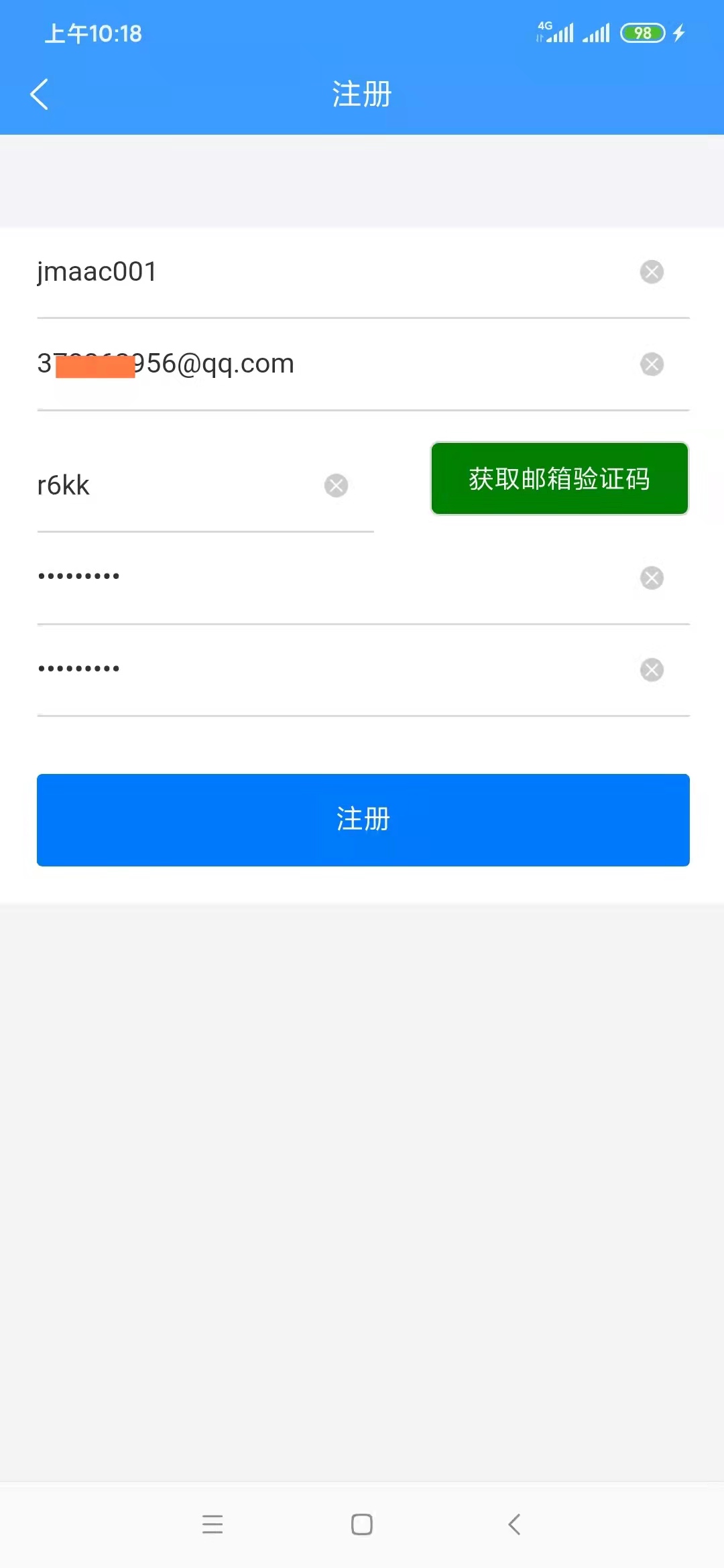
2. Open the APP. The first time you open it, you will be redirected to the login page. If you do not have an account, click "Register Account" to enter the registration page. It should be noted that registration requires an email account to receive a verification code. First, enter a valid email address, such as 3333333@qq.com. It is recommended to use a QQ email or a domestic email address. For reasons we all know, foreign email addresses may not receive the email, or even if received, may not be able to open it.
As for why we don't use a mobile phone number for registration, it's to save costs. A text message costs 1 cent, which is really unaffordable. Please understand. On the other hand, some users are sensitive about mobile phone numbers and are unwilling to give them out casually.
3. After successful registration for the first time, you will be redirected to the login page to log in to the app. You will be automatically logged in afterward unless you uninstall the app. After successful login, you will be automatically redirected to the device configuration homepage.

5. To add a device, select "My Devices" to access the device list, as shown below:
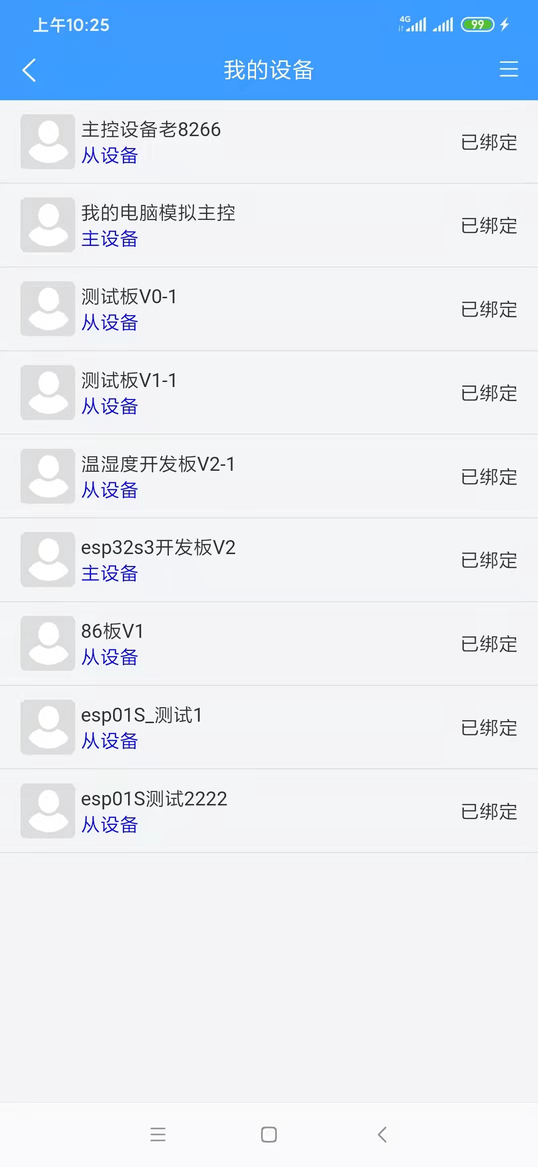
6. To bind a device, ensure that the device is successfully network-configured and that your phone and device are connected to the same Wi-Fi network (this is necessary; otherwise, the app will not be able to find the device). On the page shown above, click "Select Device" to access the device selection page, as shown below.
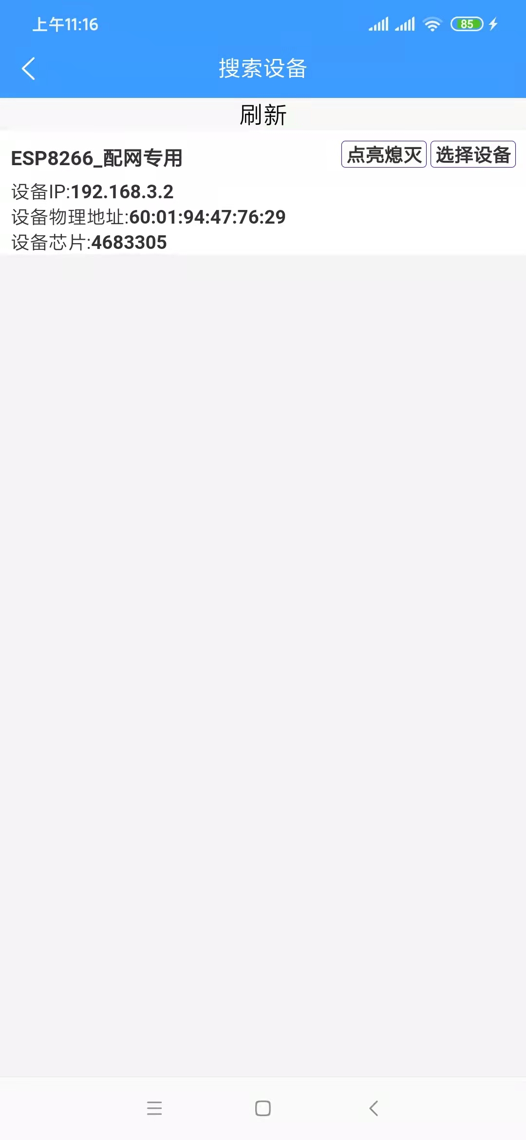
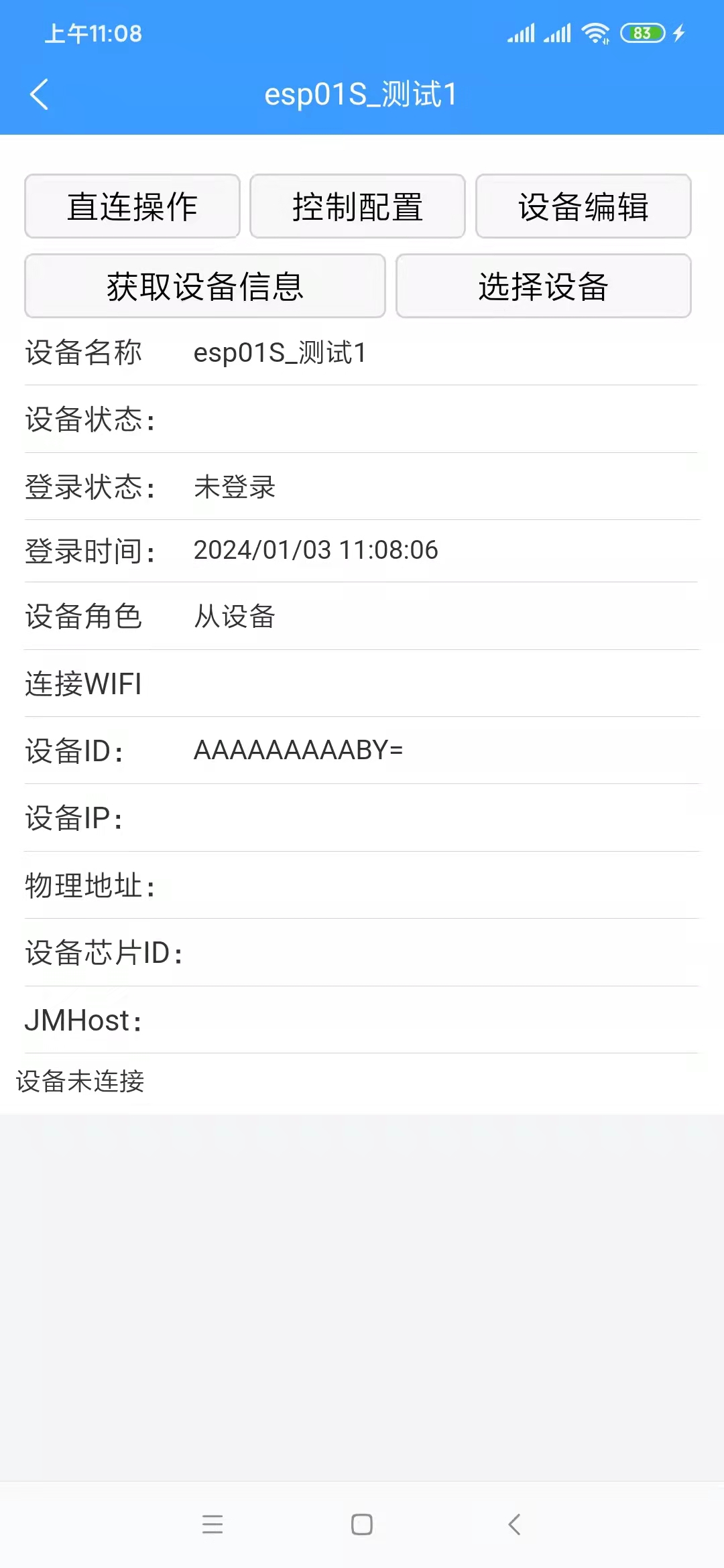
If multiple devices are not yet network-configured and are powered on, this list will display multiple available devices. If there are multiple devices but you are unsure which one is which, click "On/Off" in the list. The device's onboard LED will flash on and off. Clicking "On/Off" again will stop the LED from flashing. Clicking "Select Device" will return you to the device details page, which will display more device information. A "Confirm Binding" button has been added to the button bar. Clicking this button will successfully bind the device.
7. Device roles: Currently, there are three device roles:
Independent Device: This device can exist independently and is not controlled by other devices. It is suitable for scenarios requiring individual control, or scenarios where there is no master device yet and you want to test this device independently.
Master Device: Similar to Tmall Genie, this is the ESP32S3 board. You can control other slave devices through this board. Slave
Device: Similar to an independent device, but it can be added to a master device and controlled by the master device. For example, for devices based on the ESP8266 that are not configured for voice input but still require voice control, this device can be set as a slave device and added to the master device. The master device receives voice control commands to control this device. The attached video shows two ESP8266-based boards, both of which can be used as slave devices.
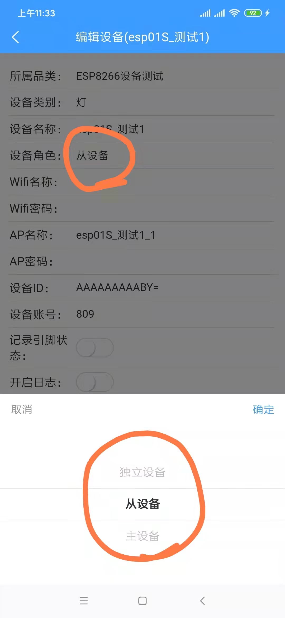
Generally, the ESP32S3 board is set as the master device, and other devices are set as slave devices. Of course, they can also all be set as independent devices, in which case there is no relationship between the devices.
8. After successful device
binding, a "Control Configuration" option will appear on the device details page (see image below). Initially, this list is empty.
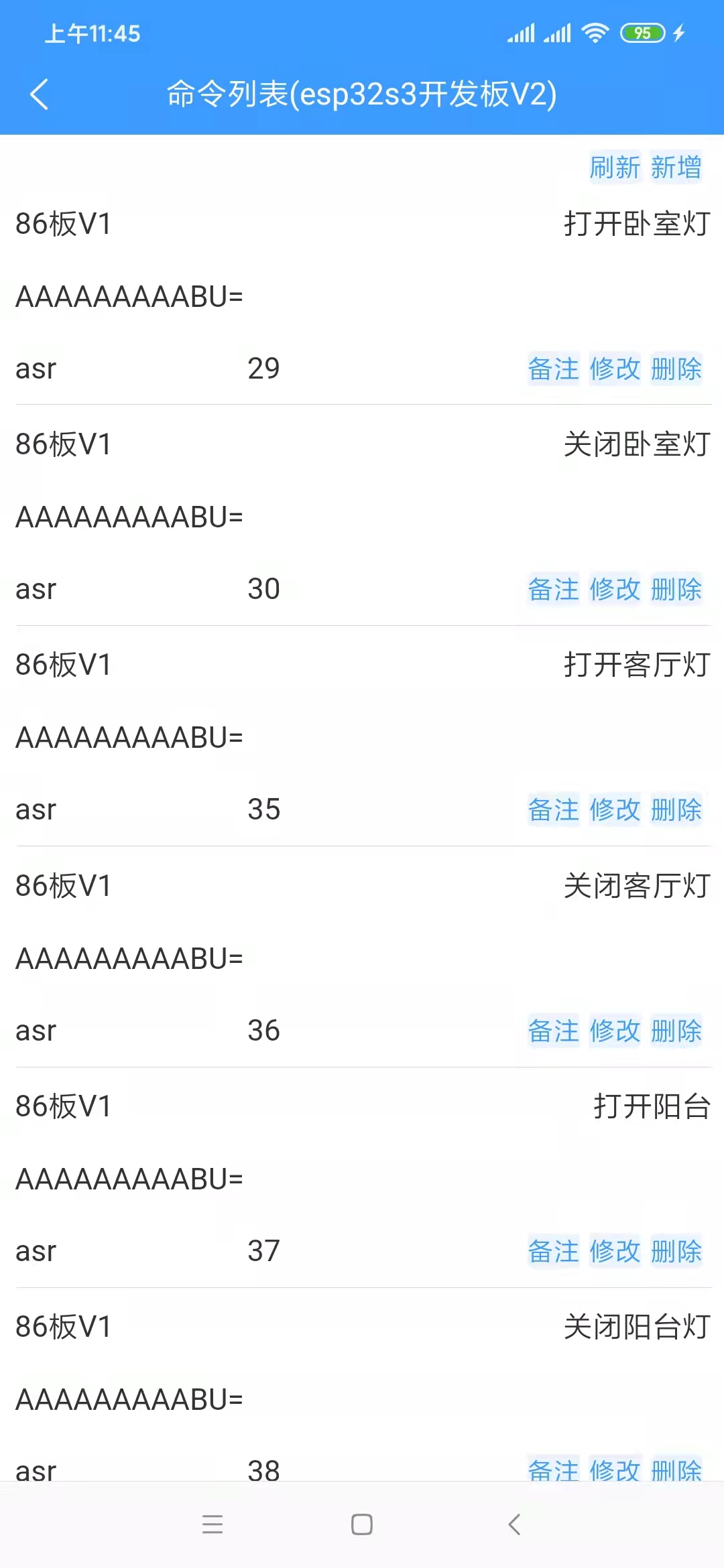
The Chinese text displayed in the upper right corner of each row is the command term. Speaking this command term to the ESP32S3 board will execute the command.
In the upper right corner of the list, there is a "Add" label. Clicking it will take you to the command addition page, as shown below.

Since we are adding a command under the master device, select the slave device to control, provided you already have a slave device.
The command name is the voice command term; the number of characters should be appropriate, preferably between 3 and 8 characters.
The command pinyin does not need to be filled in; it will be automatically generated after successful saving.
The command description is optional.
Select "Voice Command" for the command source; the other option is "Infrared Remote Control."
The command ID does not need to be filled in; the system will create it automatically.
Select "GPIO Control" for the command function.
Execution Instructions: This refers to the voltage level of the microcontroller pins. Switching a light on/off essentially controls the voltage level of the pins connected to the microcontroller. Conversely, theoretically, any device that can be controlled via microcontroller pins can be controlled through this configuration, not just lights. This example uses a light to illustrate the concept.
ClientId: There is only one option; select it.
After confirming the above configuration is complete and clicking "Save Successfully," return to the command list. You can "Refresh" to see if it appears in the list. It's important to note that the backend caches this list for a period of time to consider performance and cost. Requests within this timeframe retrieve data from the cache instead of querying the database. Therefore, if the list doesn't display the latest added or modified data, wait 1 to 5 minutes and refresh the list to see the latest data. After
adding the command, assuming the device is functioning correctly, you can speak the command words to the master device to control it. For example, "Xiao Ai, turn on the balcony light." "Xiao Ai" is the wake-up word and needs to be spoken separately from the command word. The device can only receive the command word after it is woken up.
If you are modifying commands, since the device also has a local command cache, after saving successfully, you need to click either the "Refresh Device Cache" or "Synchronize Device Voice Commands" button to ensure the device updates its local cache promptly.
In fact, some of the above configurations can be omitted; they are shown here primarily from a developer's perspective. From the user's perspective, it can certainly be made even simpler.
Voice interaction
is relatively simple to use. Press and hold the OK button on the board; the RGB light on the main control board (if present) will light up. Say your question, and then release. The response time varies depending on the length of the question and the length of the returned information, generally within one minute. It is recommended that you keep your question under 5 seconds, and immediately say your question after the RGB light turns on, because the board is already recording audio when the RGB light turns on, consuming voice data even if you don't speak. The process of converting speech to text, requesting the text result from the language model, and then converting the text result back to speech, each stage takes a considerable amount of time. For a microcontroller (the ESP32S3 only has a 240MHz clock speed and 512KB RAM, which already surpasses most microcontrollers), this is quite impressive. Don't compare a microcontroller to a computer CPU; they are not comparable!
86-board light switch demonstration.mp4
esp01 micro switch.mp4
jmicro_v3.0.1_all.bin
Demonstration of simultaneous voice and infrared remote control of a 220V light.mp4
Voice conversation.mp4
JMicro.apk
PDF_esp32S3 project.zip
Altium_esp32S3 project.zip
PADS_esp32S3 project.zip
BOM_esp32S3 project.xlsx
96562
Heart-shaped lights
This heart-shaped lamp is made using the Air32F103CCT6 microcontroller. It's simple to make and would be a very nice gift for your girlfriend. Even tech guys can be very romantic.
This project is a heart-shaped lamp made based on the air32f103cct6 microcontroller. It includes a power supply circuit, a crystal oscillator circuit, a reset circuit, and a microcontroller circuit. The code was written to achieve the effects of all LEDs on, all LEDs off, and a running light effect.
int main(){ SysTick_Init(72); // Delay function initialization LED_Init(); // Initialize the hardware interface connected to the LED LED_Init_B(); // Initialize the hardware interface connected to the LED LED_Init_A(); // Initialize the hardware interface connected to the LED LED_Init_B1(); LED_Init_A1(); while(1) { siliangsimie();//All on liangliangliangmie();//All off yiliangyimie();//Move from left to right liangbianliudo();//Move to both sides liangmie();//The colored lights light up sequentially from left to right, and then turn off sequentially liangbuanliang();//Both sides light up and turn off simultaneously liangliangliangmie();//All off
} }
The above is the main function code.
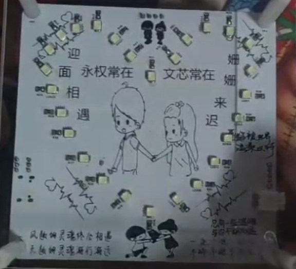
Figure 1: Circuit diagram
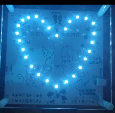
Figure 2: Circuit diagram Demonstration effect
The attached code and demonstration video have been uploaded.
WeChat_20240102143636.mp4
Heart-shaped lamp.rar
PDF_Heart-shaped Lights.zip
Altium_Heart-shaped Light.zip
PADS_Heart-shaped Lights.zip
BOM_Heart-shaped Light.xlsx
96565
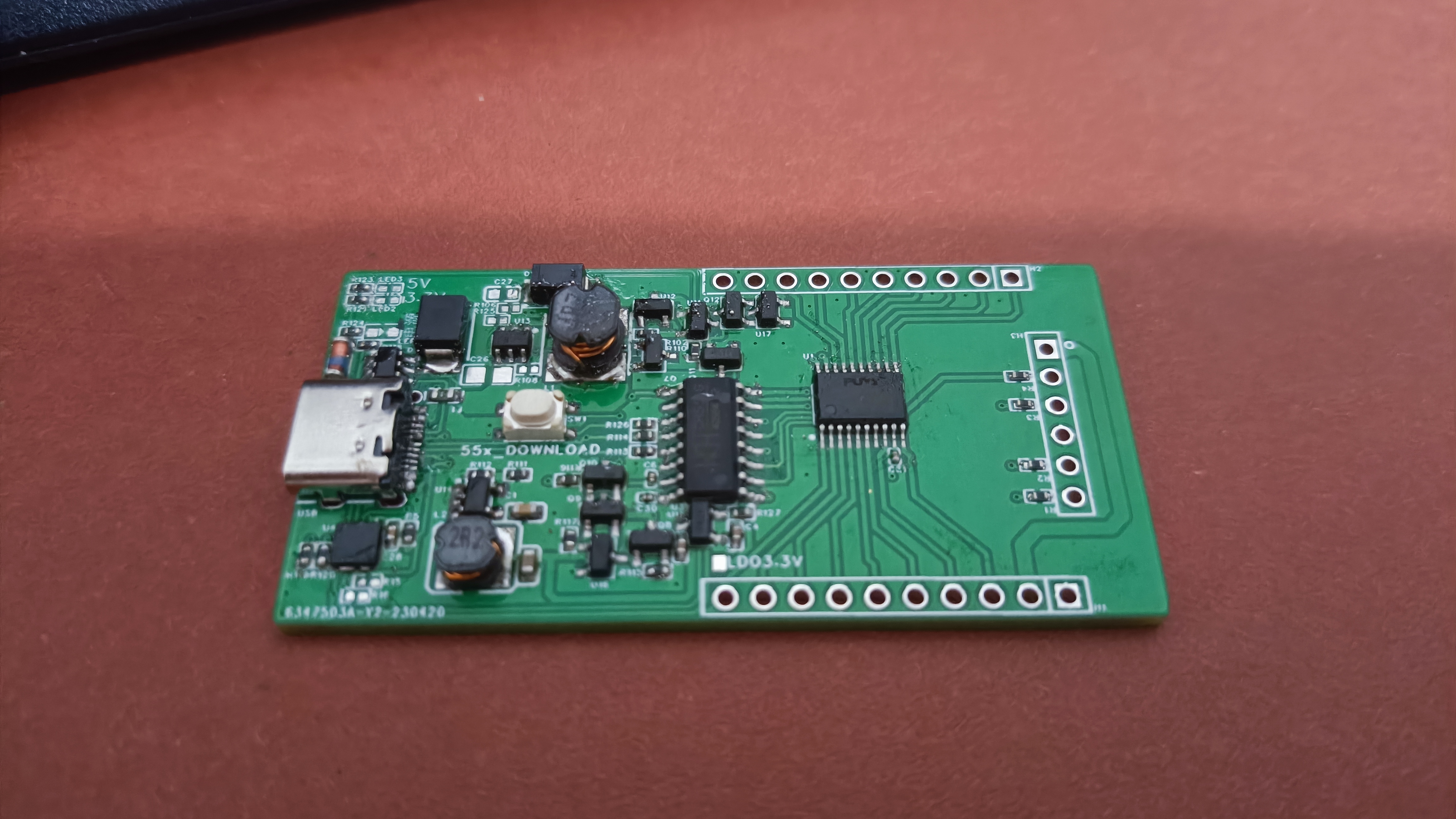
CH552 software emulation USB PD decoy
This project uses the CH552 general-purpose microcontroller without a PD PHY to transmit and receive PD signals. The microcontroller peripherals only use analog comparators, converters, and timers. All other signal processing is implemented in software and using external resistors and diodes. This method can also be applied to other general-purpose microcontrollers.
More information can be found in the example code in ch55xduino.
This project uses a general-purpose microcontroller (CH552) to receive and send USB PD signals via the CC line, without any peripherals. Only an analog comparator and a timer are used to receive signals. GPIOs with clamping diodes are used to send signals. The example code makes the CH552 act as a USB PD SINK controller and requests a programmable voltage from the PD/PPS charger.
This approach can also be ported to any general-purpose microcontroller with a comparator, ADC, and digital output.
For a simpler circuit, the CH549 can also be used. The same code will significantly simplify the peripheral circuitry by utilizing the internal voltage reference and low-voltage output capability.
How it works:
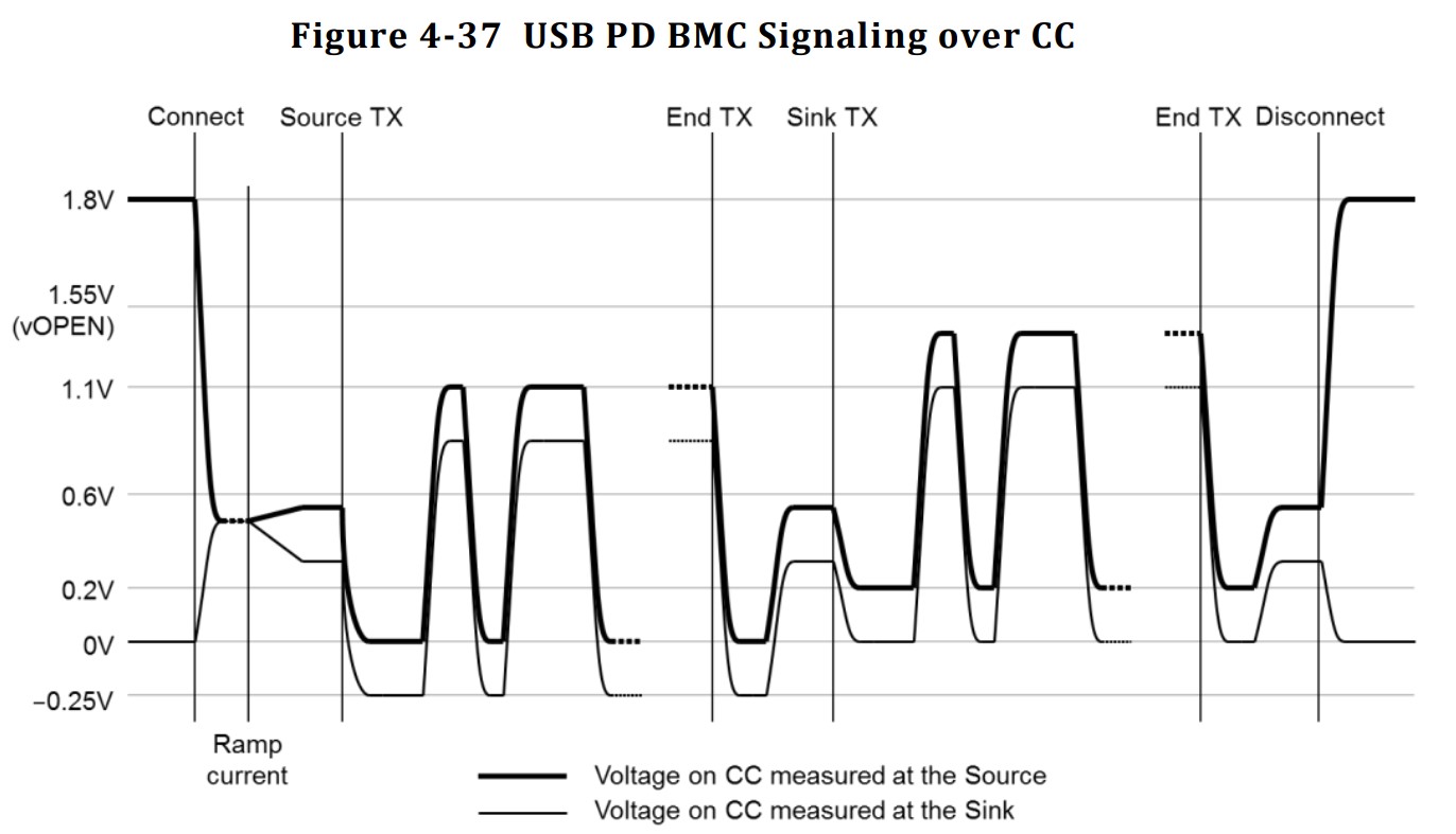
USB PD exchanges data between the source and sink devices via the CC line in the USB Type-C connector using the BMC (Biphase Mark Code). However, the maximum communication voltage is approximately 1~1.2V, so it cannot be directly interconnected with the microcontroller's I/O ports.

On the input side, an analog comparator compares the signal to a 0.6V reference voltage, thus converting the signal into a digital signal. The software uses a timer to measure the time difference between transitions and decodes the BMC into binary.
On the output side, the output voltage is clamped to 1V through a 1K resistor, a general-purpose diode, and two Schottky diodes. The cathode of a series diode is connected to another GPIO, making the clamping controllable. Therefore, any digital output will be clamped to 0-1V.

After the signal is decoded from the BMC, the software looks for a preamble consisting of alternating 1s and 0s. Once the preamble ends, the software records the binary data in 5-bit groups. After the preamble ends, we check the SOP, perform 5b4b decoding, and check the CRC. If everything is normal, we parse the data packet using the USB PD protocol.
The data transmission process is similar: we generate a CRC, encode the data using 4b5b, add the SOP and EOP, and then encode the data back using the BMC.
PowerDelivery.zip
CH552_typeC_Power_Delivery.sch
CH552_typeC_Power_Delivery.brd
CH549_typeC_Power_Delivery.sch
CH549_typeC_Power_Delivery.brd
PDF_CH552 Software Simulator USB PD Decoy.zip
Altium_CH552 software emulator for USB PD decoys.zip
PADS_CH552 software emulates a USB PD decoy.zip
BOM_CH552 Software Emulator for USB PD Deceptive.xlsx
96566
electronic
 ![IMG_20230508_045716.jpg]]
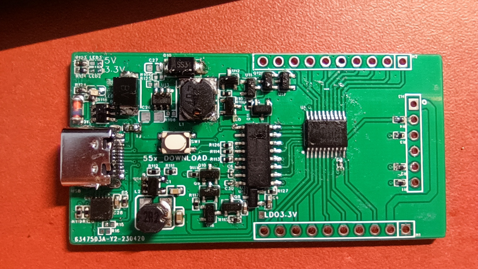


 京公网安备 11010802033920号

 AD408M181RTB-5


