1. Hardware Design:
First, the screen. It's a 2.0-inch LCD screen, ST7789. The module porting manual mentioned someone had already programmed for this screen, and I initially thought I could just copy and use it. However, inexplicably, the screen wouldn't light up.
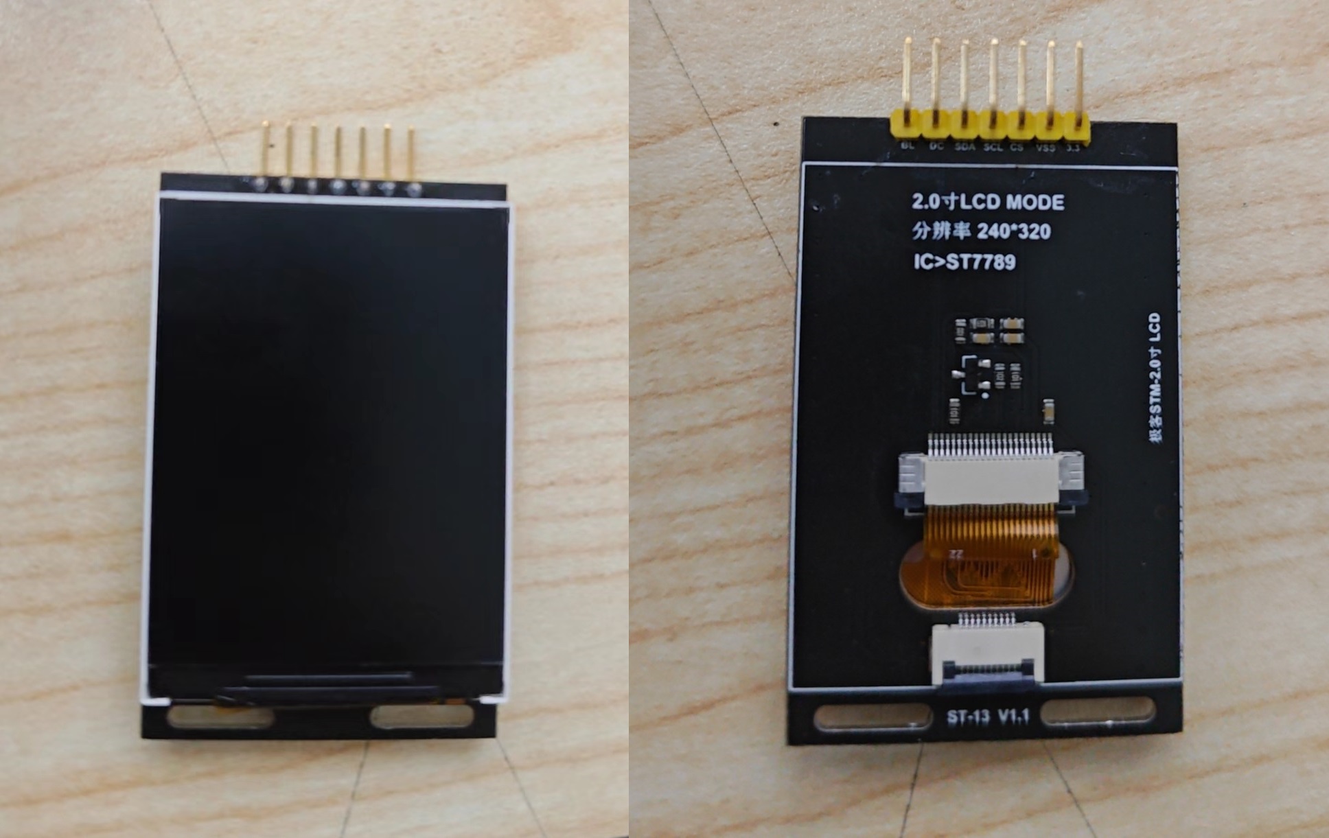
After spending some time troubleshooting software issues, I discovered that connecting the screen with DuPont wires worked, but plugging it into the expansion board failed. The problem was obvious: the expansion board was designed for bare screens, but my screen already had a built-in driver circuit, hence the inability to light up. I
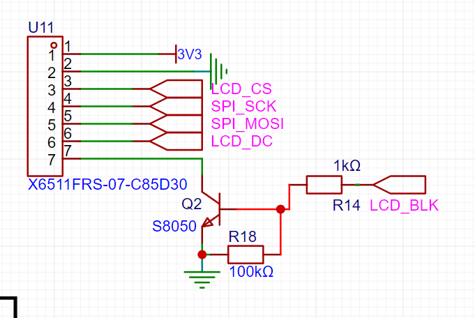
had initially followed the official circuit design, which used an S8050 and some resistors for the LCD_BLK circuit. However, this 2.0-inch screen already had these circuits, making it redundant and causing an open circuit in LCD_BLK. Since I had already printed the board, modifying it would require reprinting, which was too much trouble. So, I removed R18 and replaced R14 and Q2 with a 0Ω resistor, effectively short-circuiting this part.

The screen then lit up successfully.
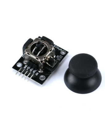
Next is the joystick issue. The official open-source project doesn't specify which joystick model is used. I found joysticks on Taobao, but I didn't know if JLCPCB had packaged them, so I simply bought a cheap joystick module and connected it using bent pins and headers. It has five pins, but only four are actually used. The SW pin is the button pin for this joystick module, which isn't used here.
2. Software Part
2.1 Hardware SPI Driver for the Screen
As mentioned earlier, the JLCPCB development board documentation already includes the program for this screen, but this doesn't mean it can be used directly. Although both are 2.0-inch TFT and ST7789, screens from different manufacturers have slight differences (although sellers usually provide example code). The one I have was purchased from an unknown small seller on Taobao. Its biggest difference from the screen in the official documentation is the absence of the RES pin, which led me to initially believe that this was the reason the screen wouldn't light up.
To save trouble, I ported the official example code by modifying the pin macro definitions in lcd_init.h. I changed SPI1 to SPI4 and changed each pin to its corresponding pin.
//-----------------LCD Port Port Porting----------------
//VCC - 3.3V
//SCL - PF7 SPI4_SCK
//SDA - PF9 SPI4_MOSI
//RES - PD0 (can be connected for reset) (This screen does not have RES, you can delete it or leave it as is)
//DC - PA6
//CS - PA4
//BLK - PA7
#define RCU_LCD_SCL RCU_GPIOF//SCK
#define PORT_LCD_SCL GPIOF
#define GPIO_LCD_SCL GPIO_PIN_7 #define RCU_LCD_SDA
RCU_GPIOF//MOSI
#define PORT_LCD_SDA GPIOF
#define GPIO_LCD_SDA GPIO_PIN_9
#define RCU_LCD_CS RCU_GPIOA//NSS
#define PORT_LCD_CS GPIOA
#define GPIO_LCD_CS GPIO_PIN_4
#define RCU_LCD_DC RCU_GPIOA //DC
#define PORT_LCD_DC GPIOA
#define GPIO_LCD_DC GPIO_PIN_6
#define RCU_LCD_RES RCU_GPIOD//RES
#define PORT_LCD_RES GPIOD
#define GPIO_LCD_RES GPIO_PIN_0
#define RCU_LCD_BLK RCU_GPIOA//BLK
#define PORT_LCD_BLK GPIOA
#define GPIO_LCD_BLK GPIO_PIN_7
#define RCU_SPI_HARDWARE RCU_SPI4
#define PORT_SPI SPI4
#define LINE_AF_SPI GPIO_AF_5
2.2 ADC Reading Joystick Data
When using the joystick function, the ADC needs to be initialized, and then the ADC can start detecting the joystick output variables.
void adc_config(void)
{
/* enable ADC0 clock /
rcu_periph_clock_enable(RCU_ADC0);
/ config ADC clock /
adc_clock_config(ADC_ADCCK_PCLK2_DIV8);
/ reset ADC /
adc_deinit();
/ configure the ADC mode /
adc_sync_mode_config(ADC_SYNC_MODE_INDEPENDENT); // All ADCs operate in independent mode
/ ADC contineous function disable /
adc_special_function_config(ADC0, ADC_CONTINUOUS_MODE, DISABLE); // Disable continuous mode
/ ADC scan mode disable /
adc_special_function_config(ADC0, ADC_SCAN_MODE, DISABLE); // Disable scan mode
/ ADC data alignment config /
adc_data_alignment_config(ADC0,ADC_DATAALIGN_RIGHT); // LSB alignment, low-order alignment
/ ADC channel length config /
adc_channel_length_config(ADC0,ADC_REGULAR_CHANNEL,1U); // ADC regular channel length is 1
/ enable ADC interface /
adc_enable(ADC0);
/ wait for ADC stability /
delay_1ms(1);
/ ADC calibration and reset calibration /
adc_calibration_enable(ADC0); // ADC calibration
/ wait for ADC stability /
delay_1ms(1);
/ adc pin initialization */
adc_gpio_init();
}
3. NES simulator code porting
The original code was ported to the NES simulator code of Zhengdian Atom. LCSC has already ported it to the Liangshanpai development board, so I modified the source code of LCSC here.
First, I modified the joystick's reading code because I encountered a problem during testing: all buttons except the Reset button were malfunctioning. Initially, I thought it was a hardware issue, but after checking the circuit design and soldering, I ruled out hardware problems. I also checked the button output using a serial port assistant, which was normal.
Finally, I discovered the problem was with the joystick itself. Because the joystick module normally reads values greater than 3000 from the ADC, the joystick continuously outputs a five_key_down signal, causing it to be occupied and preventing the buttons from functioning properly, resulting in me being stuck on the start screen. Changing the condition to 4000 resolved the problem. Incidentally, I also discovered that the Y-axis of this rocker model is reversed, so I replaced the UP and down buttons.
//adc_Key.c
/* Five-way key scanning function */
five_key_enum five_way_key_scan(void)
{
uint16_t adcXValue,adcYValue;
adcXValue = adc_channel_sample(ADC_CHANNEL_1); // Sample
adcYValue = adc_channel_sample(ADC_CHANNEL_11); // Sample
if (adcYValue >= 4000 )// Modify to 4000
{ //
return five_key_up;
}
if ( adcYValue <= 1000)
{ //
return five_key_down;
}
if (adcXValue >= 4000 )
{ //
return five_key_left;
}
if ( adcXValue <= 1000)
{ //
return five_key_right;
}
return five_key_null;
}
Next is the code for the screen display in nes_ppu.c
//(nes_ppu.c)
void scanline_draw(int LineNo)
{
uint16 i;
uint16_t sx=17,ex=257;
do_scanline_and_draw(ppu->dummy_buffer);
// sx = 17;
// ex = 240+17;
LCD_CS_Clr();
LCD_DC_Clr();//Write command
spi_i2s_data_transmit(SPI4, 0x2a);
while(RESET == spi_i2s_flag_get(SPI4, SPI_FLAG_TBE));
LCD_DC_Set();//Write data
spi_i2s_data_transmit(SPI4, 0);
while(RESET == spi_i2s_flag_get(SPI4, SPI_FLAG_TBE));
spi_i2s_data_transmit(SPI4, 0);
while(RESET == spi_i2s_flag_get(SPI4, SPI_FLAG_TBE));
spi_i2s_data_transmit(SPI4, 0);
while(RESET == spi_i2s_flag_get(SPI4, SPI_FLAG_TBE));
spi_i2s_data_transmit(SPI4, 240);
while(RESET == spi_i2s_flag_get(SPI4, SPI_FLAG_TBE));
LCD_DC_Clr();//Write command
spi_i2s_data_transmit(SPI4, 0x2b);
while(RESET == spi_i2s_flag_get(SPI4, SPI_FLAG_TBE));
LCD_DC_Set();//Write data
spi_i2s_data_transmit(SPI4, (LineNo+20)>>8);
while(RESET == spi_i2s_flag_get(SPI4, SPI_FLAG_TBE));
spi_i2s_data_transmit(SPI4, LineNo+20);
while(RESET == spi_i2s_flag_get(SPI4, SPI_FLAG_TBE));
spi_i2s_data_transmit(SPI4, (LineNo+20)>>8);
while(RESET == spi_i2s_flag_get(SPI4, SPI_FLAG_TBE));
spi_i2s_data_transmit(SPI4, LineNo+20);
while(RESET == spi_i2s_flag_get(SPI4, SPI_FLAG_TBE));
LCD_DC_Clr();//Write command
spi_i2s_data_transmit(SPI4, 0x2c);
while(RESET == spi_i2s_flag_get(SPI4, SPI_FLAG_TBE));
LCD_DC_Set();//Write data
for(i=sx;idummy_buffer[i]]>>8);
while(RESET == spi_i2s_flag_get(SPI4, SPI_FLAG_TBE));
spi_i2s_data_transmit(SPI4, NES_Palette[ppu->dummy_buffer[i]]);
}
while(RESET == spi_i2s_flag_get(SPI4, SPI_FLAG_TBE));
LCD_CS_Set();
// }
}


 京公网安备 11010802033920号

 MI-QC2ML-IVY


