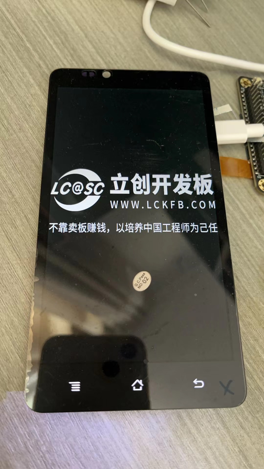
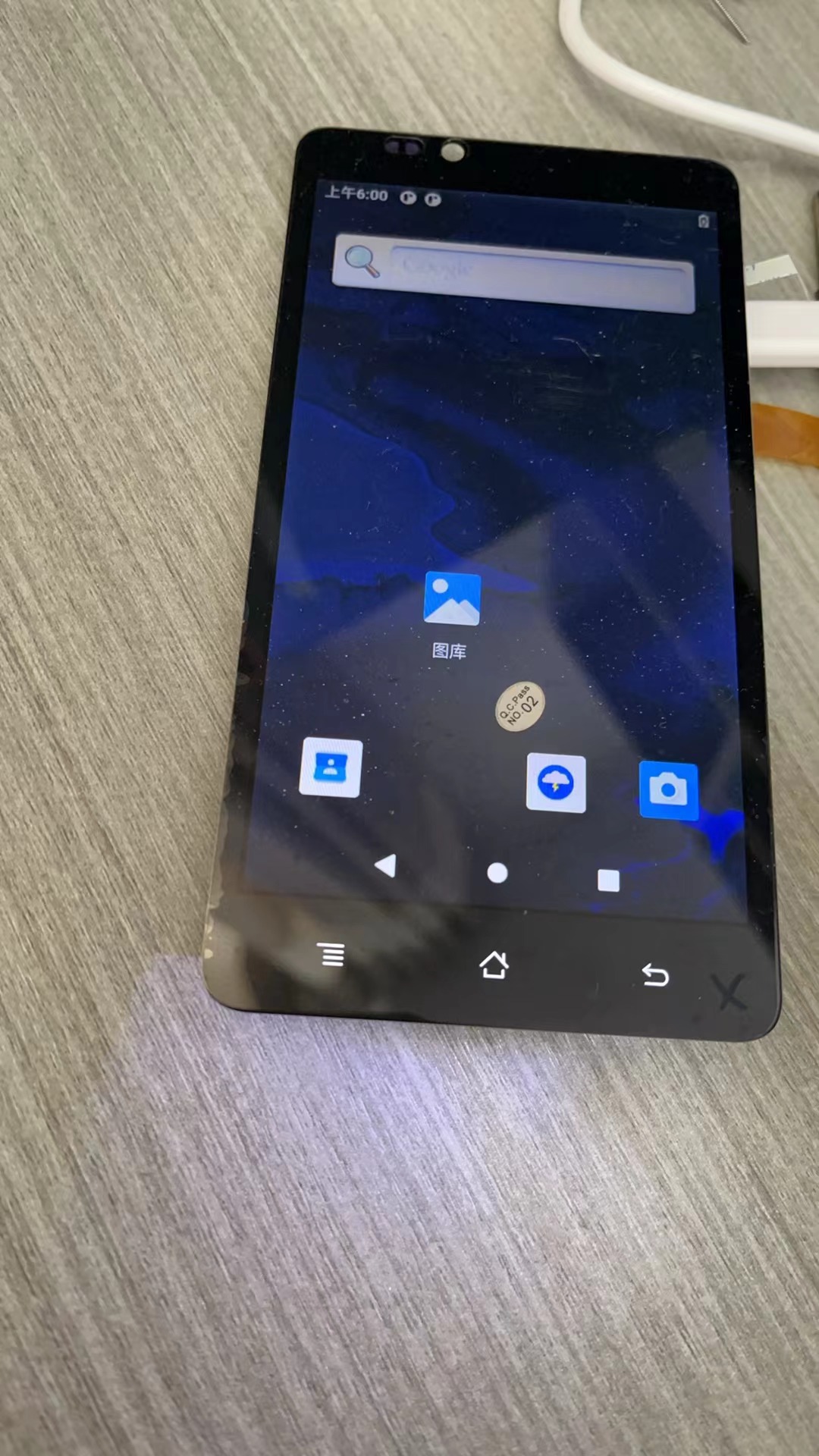
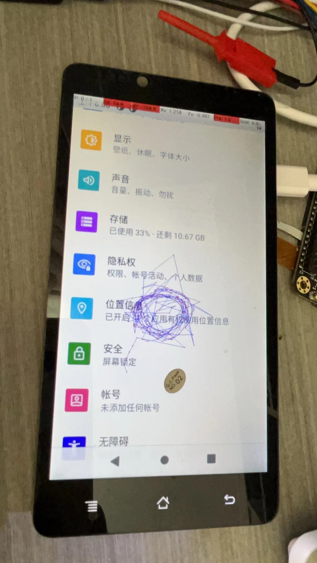
Using the Taishan School's adapter board, I successfully lit up the phone screen. Unfortunately, I only realized I hadn't registered after finishing the project, and then the course ended.
If you use the Taishan School's backlight circuit, remember to modify the drive current; otherwise, screen burn-in is highly likely. A phone screen only needs 10mA to be bright enough, while the Taishan School requires 110mA.
This is a battery-free solar-powered flashlight; it lights up when there is light, but it will never light up when there is no light.
4.3-inch RGB capacitive touchscreen expansion board V2.0; touch GT911; resolution 800*480; the difference between V2.0 and V1.1 is that the screen is from Yaoyuan Hong, which is cheaper and more suitable for installation with the RTC_LCD motherboard;
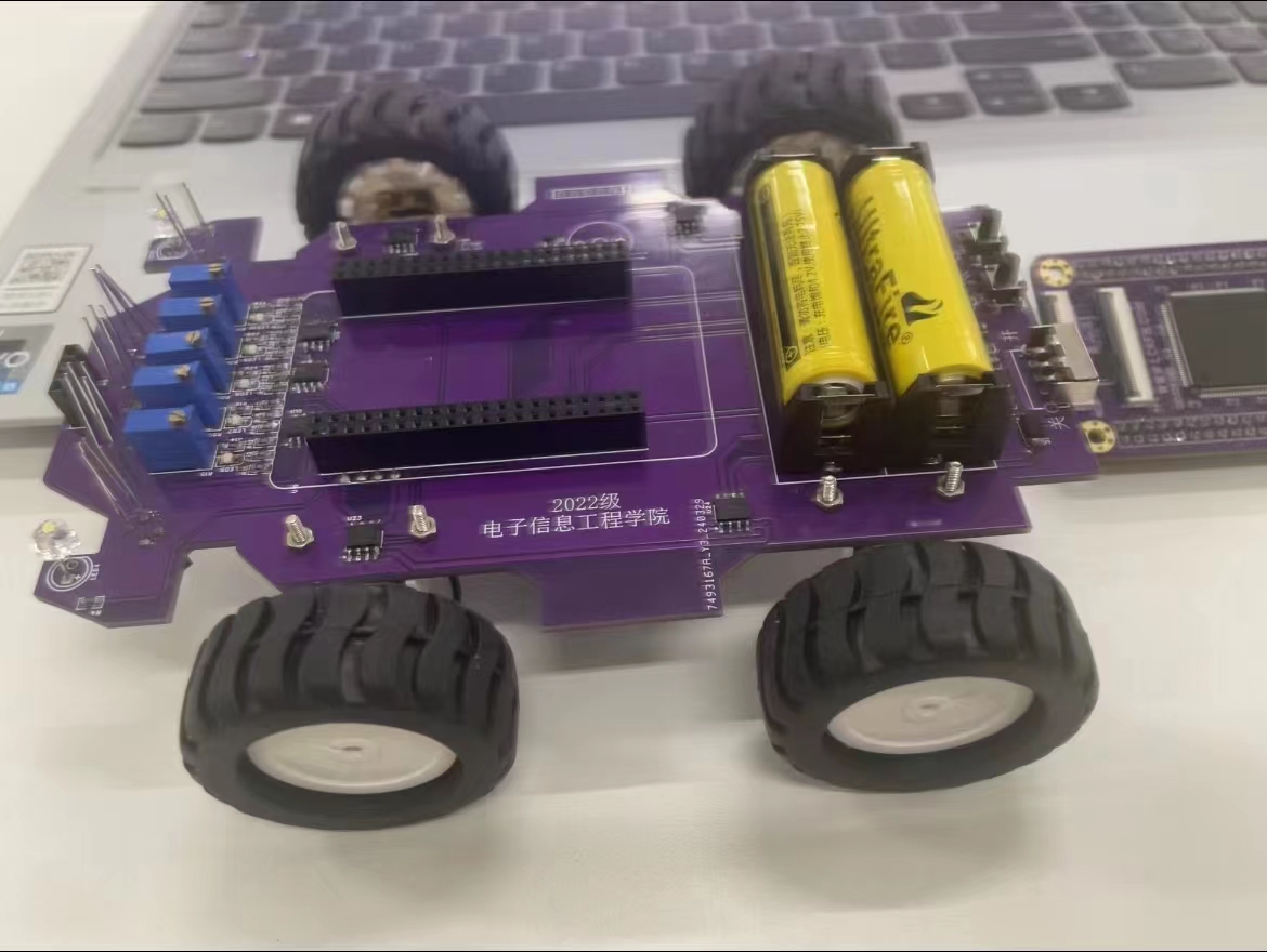
Suitable for electronics enthusiasts and beginners to learn basic projects; embedded courses are taught using a smart car and Liangshanpai development board as a whole; it serves as a reference case for university course design and graduation projects, allowing students to complete a smart car project according to the course design requirements using the LCSC Liangshanpai core board.
The STC32G12128K is a high-performance 32-bit ARM Cortex-M3 core microcontroller from STC (Semiconductor Manufacturing Corporation). It features rich peripheral interfaces and functions, making it suitable for applications requiring low power consumption and high performance.
The STC32G12128K minimum system board is a development board based on the STC32G12128K microcontroller, used for embedded system development and prototyping. The system board consists of:
1. Main control chip: STC32G12128K, a 32-bit ARM Cortex-M3 core microcontroller from STC (Semiconductor Manufacturing Company). It features rich peripherals and functions, suitable for low-power applications and high-performance requirements. 2. Clock and crystal oscillator: A typical minimum system board includes a crystal oscillator and related clock circuitry to provide the microcontroller with the required clock frequency and stability. 3. Power management: Includes power input and necessary power management circuitry to ensure the microcontroller and related peripherals function properly. 4. Debug interface: Usually provides a standard debugging interface, such as SWD (Serial Wire Debugging), so developers can debug and download programs using debugging tools (such as ST-Link). 5. Pin Expansion Interface: Provides all or some of the microcontroller's pins, typically via pin headers or sockets, facilitating the connection of external devices and modules, such as sensors, displays, and communication modules. 6. Development Support: Provides corresponding development toolchains and development environment support, such as STC's official integrated development environment (IDE) or third-party support. For product development teams that need to use the STC32G12128K as the core, the minimum system board can serve as a starting point for development, quickly verifying design schemes and functions.
Five-wire servos are very cheap on the market. Unlike ordinary servos, the servo control board I made uses serial 485 communication (it's not designed for model airplanes).
The advantages of this type of servo control board are: simple wiring, all servos are connected to a bus consisting of 4 wires (+5V GNDAB).
The purpose of this design
is to create a servo control board that communicates via 485 serial communication. Many servos are available on the market; they are large, powerful, and quite inexpensive. I bought mine for 1.8 yuan each. (See the picture below.)
Removing a good servo control board or buying a new one seems wasteful, as the cost is higher than the servo itself. Therefore, I decided to make my own. Using a model aircraft remote control is one method, but I don't like it because my ultimate goal is to use these servos to make toys like robotic arms. I prefer to control them directly via computer, as I can program and change the movements at any time.
Thus, the design aims to create a simple (easy for beginners) and low-cost (no more than 5 yuan, excluding labor costs; in fact, mine, including the servos, cost less than 5 yuan) servo control board that communicates via 485 serial port. (I looked into it, and it seems to be called a bus servo.)

The main components of
a servo include a motor (two wires) and a potentiometer (three wires), hence the five wires. Because the internal space of the servo motor is small and cannot accommodate too many large components, surface-mount components are used in this design, and some protection circuits are omitted as much as possible.
The main components are as follows:
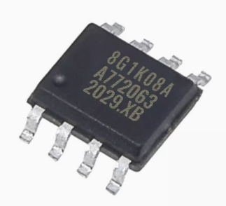
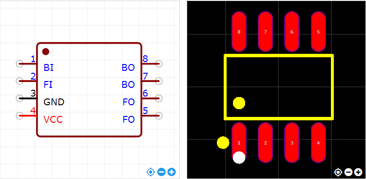
1. One STC8G1K08A-36I-SOP8 microcontroller (main control chip)
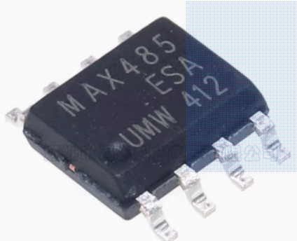
2. One MAX485-SOP8 (for communication)
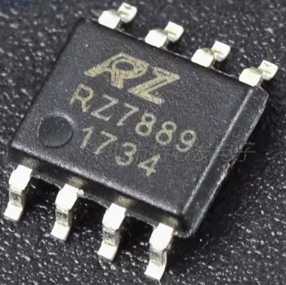
3. One RZ7889-SOP8 (motor driver)
Other non-essential components:
4. One 1kΩ 0603 resistor (current limiting resistor for LED; resistance value is not required to be 1kΩ, 5.1kΩ or 10kΩ are also acceptable, the LED will still light up)
5. One 0603 LED (for indicating communication status)
6. One 100nF 0603 capacitor (two capacitors are mainly used for filtering to reduce voltage fluctuations and interference to the microcontroller)
7. One 10uf 0603 capacitor
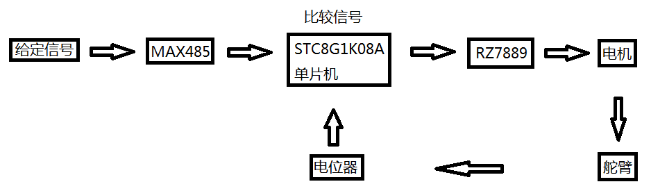
Overall design concept: The microcontroller compares the magnitude of the given signal and the potentiometer feedback signal, and controls the motor rotation through the RZ7889, thereby changing the potentiometer signal until the potentiometer signal and the given signal are equal.
Main component pin diagrams
: 1. STC8G1K08A-36I-SOP8 pin diagram;

2. MAX485-SOP8 pin diagram;

3. RZ7889-SOP8 pin diagram.
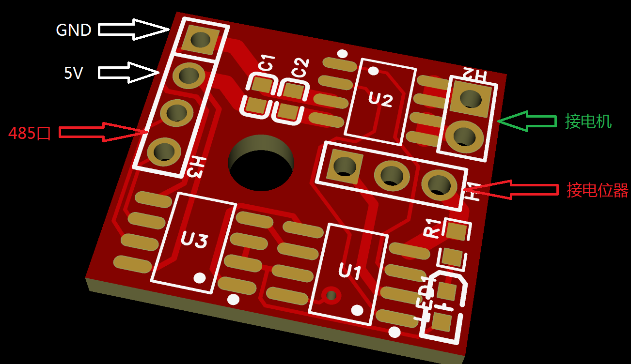
PCB description:
The three sockets on the PCB do not need to be purchased; they are for direct soldering. I haven't explicitly labeled the connections for the 485 port, motor, and potentiometer because I'm also unsure about these connections and they are easily reversed. When soldering the first PCB (if you have many servos to modify), after soldering the three main chips, generally solder the 485 port first, then use the computer to communicate with the board to check if communication is normal. If communication fails, swap the order of the two wires on the 485 port (switch on the 485 port, not on the PCB; you can then solder all your boards according to this order). After successful communication, solder the potentiometer, manually move the servo arm, and check if the feedback data on the computer is normal. If it is normal, then solder the motor. Note that the motor wiring sequence may be reversed, so be careful. Power off frequently during testing. Avoid applying excessive steering input. If normal, the servo will stop at the correct position; otherwise, it will reach its limit and get stuck. Therefore, power off immediately and adjust the motor wiring sequence. After confirming the wiring sequence for the control board, solder the control board according to the sequence tested earlier. Additionally
, it's best to download the firmware before soldering the microcontroller. Otherwise, downloading it after soldering can be difficult, especially for beginners. Note: The firmware is in the attachment, as is the source code.
Software Description (My abilities are limited; I can only write programs at this basic level. If anyone likes this project, I don't mind if the program is copied and modified. The protocol in the program was just something I came up with on a whim, without much thought, since it's just for fun.)
#include "reg51.h"
#include "intrins.h"
#include "stdlib.h"
#define FOSC 11059200UL
#define BRT (65536 - FOSC / 9600 / 4)
sfr AUXR = 0x8e;
sfr P5
= 0xC8; sfr P0M1 = 0x93;
sfr P0M0 =
0x94;
sfr P1M1 = 0x91;
sfr P1M0 = 0x92; sfr P2M1 = 0x95;
sfr P2M0 = 0x96;
sfr P3M1 = 0xb1;
sfr P3M0 = 0xb2;
sfr P4M1 = 0xb3;
sfr P4M0 = 0xb4
; sfr P5M1
= 0xc9; sfr P5M0 = 0xca;
sfr IAP_DATA = 0xC2; //EEPROM related registers
sfr IAP_ADDRH = 0xC3;
sfr IAP_ADDRL = 0xC4;
sfr IAP_CMD = 0xC5;
sfr IAP_TRIG = 0xC6;
sfr IAP_CONTR = 0xC7;
sfr IAP_TPS = 0xF5;
sfr ADC_CONTR = 0xbc; //ADC related registers
sfr ADC_RES = 0xbd;
sfr ADC_RESL = 0xbe;
sfr ADCCFG = 0xde;
sfr P_SW2 = 0xba;
#define ADCTIM (*(unsigned char volatile xdata *)0xfea8)
sbit d1= P5^4;
sbit d2= P5^5;
sbit led=P3^1;
sbit RS485_DIR = P3^2;
bit flagFrame = 0; // Frame reception completion flag, i.e., a new frame of data has been received
bit flagTxd = 0; // Single byte transmission completion flag, used to replace the TXD interrupt flag
bit bit ctrl;
unsigned char m=0,n=0,mn=0,nm=0;
unsigned char cntRxd = 0; // Receive byte counter
unsigned char pdata bufRxd[64]; // Receive byte buffer
unsigned char add,setangry,myangry,minangry,maxangry;
extern void UartAction(unsigned char *buf, unsigned char len);
void Delay20ms() //@11.0592MHz
{
unsigned char i, j;
i = 216;
j = 37;
do
{
while (--j);
} while (--i);
}
//=============EEPROM=========================================================
void IapIdle()
{
IAP_CONTR = 0; // Disable IAP function
IAP_CMD = 0; // Clear command register
IAP_TRIG = 0; // Clear trigger register
IAP_ADDRH = 0x80; // Set address to non-IAP area
IAP_ADDRL = 0;
}
char IapRead(int addr)
{
char dat;
IAP_CONTR = 0x80; // Enable IAP
IAP_TPS = 12; // Set wait parameter to 12MHz
IAP_CMD = 1; // Set IAP read command
IAP_ADDRL = addr; // Set IAP low address
IAP_ADDRH = addr >> 8; // Set IAP high address
IAP_TRIG = 0x5a; // Write trigger command (0x5a)
IAP_TRIG = 0xa5; // Write trigger command (0xa5)
_nop_();
dat = IAP_DATA; // Read IAP data
IapIdle(); // Disable IAP function
return dat;
}
void IapProgram(int addr, char dat)
{
IAP_CONTR = 0x80; // Enable IAP IAP
IAP_TPS = 12; // Set wait parameter 12MHz
IAP_CMD = 2; // Set IAP write command
IAP_ADDRL = addr; // Set IAP low address
IAP_ADDRH = addr >> 8; // Set IAP high address
IAP_DATA = dat; // Write IAP data
IAP_TRIG = 0x5a; // Write trigger command (0x5a)
IAP_TRIG = 0xa5; // Write trigger command (0xa5)
_nop_();
IapIdle(); // Disable IAP function
}
void IapErase(int addr)
{
IAP_CONTR = 0x80; // Enable IAP
IAP_TPS = 12; // Set wait parameter to 12MHz
IAP_CMD = 3; // Set IAP erase command
IAP_ADDRL = addr; // Set IAP low address
IAP_ADDRH = addr >> 8; // Set IAP high address
IAP_TRIG = 0x5a; // Write trigger command (0x5a)
IAP_TRIG = 0xa5; // Write trigger command (0xa5)
_nop_(); //
IapIdle(); // Disable IAP function
}
//===============================================================================
void Delay100us() //@11.0592MHz
{
unsigned char i, j;
i = 2;
j = 109;
do
{
while (--j);
} while (--i);
}
/* /* Serial port data writing, i.e., serial port sending function, buf - pointer to the data to be sent, len - specified sending length */
void UartWrite(unsigned char *buf, unsigned char len)
{
RS485_DIR = 1; // RS485 set to send
while (len--) // Loop to send all bytes
{
flagTxd = 0; // Clear the send flag
SBUF = *buf++; // Send one byte of data
while (!flagTxd); // Wait for the byte to be sent
}
Delay100us(); // Wait for the last stop bit to complete, the delay time is determined by the baud rate
RS485_DIR = 0; // RS485 set to receive
}
/* Serial port data reading function, buf - receive pointer, len - specified reading length, return value - actual length read */
unsigned char UartRead(unsigned char *buf, unsigned char len)
{
unsigned char i;
if (len > cntRxd) // When the specified read length is greater than the actual received data length,
{ // The read length is set to the actual received data length
len = cntRxd;
}
for (i=0; i 0) // When the receive counter is greater than zero, monitor the bus idle time
{
if (cntbkp != cntRxd) // When the receive counter changes, i.e., when data is just received, clear the idle timer
{
cntbkp = cntRxd;
idletmr = 0;
}
else // When the receive counter does not change, i.e., when the bus is idle, accumulate the idle time
{
if (idletmr < 30) // When the idle timer is less than 30ms, continue to accumulate
{
idletmr += ms;
if (idletmr >= 30) // When the idle time reaches 30ms, it is determined that a frame has been received
{
flagFrame = 1; // Set the frame reception completion flag
}
}
}
}
else
{
cntbkp = 0;
}
}
/* Serial port driver function, monitors the reception of data frames, scheduling function, needs to be called in the main loop */
void UartDriver()
{
unsigned char len;
unsigned char pdata buf[40];
if (flagFrame) // When a command arrives, read and process the command
{
flagFrame = 0;
len = UartRead(buf, sizeof(buf)-2); // Read the received command into the buffer
UartAction(buf, len); // Pass the data frame and call the action execution function
}
}
/* Serial port interrupt service function */
void InterruptUART() interrupt 4
{
if (RI) // New byte received
{
RI = 0; // Clear receive interrupt flag
TR0 = 0;
if (cntRxd < sizeof(bufRxd)) // If the receive buffer is not full,
{ // Save the received byte and increment the counter
bufRxd[cntRxd++] = SBUF;
}
}
if (TI) // Byte transmission completed
{
TI = 0; // Clear transmit interrupt flag
flagTxd = 1; // Set byte transmission complete flag
}
}
void UartInit() // Serial port initialization
{
SCON = 0x50;
TMOD = 0x00;
TL1 = BRT;
TH1 = BRT >> 8;
TR1 = 1;
AUXR = 0x40;
}
void Timer0Init(void) // 5 milliseconds @ 11.0592MHz
{
AUXR |= 0x80; // Timer clock 1T mode
TMOD &= 0xF0; // Set timer mode
TL0 = 0x00; // Set initial timer value
TH0 = 0x28; // Set initial timer value
TF0 = 0; // Clear TF0 flag
TR0 = 1; // Start timer 0
ET0 = 1;
}
void main()
{
P0M0 = 0x00;
P0M1 = 0x00;
P1M0 = 0x00;
P1M1 = 0x00;
P2M0 =
0x00; P2M1 =
0x00; P3M0 = 0x00;
P3M1 = 0x08; // Set P3.3 as ADC port
P4M0 = 0x00;
P4M1 = 0x00
; P5M0
= 0xff; P5M1 = 0x00;
ADCTIM = 0x3f; // Set ADC internal timing
ADCCFG = 0x0f; // Set ADC clock to system clock /2/16
ADC_CONTR = 0x80; // Enable ADC module
ADC_CONTR |= 0x43; // Start AD conversion
ctrl=0;
d1=1;d2=1;
UartInit();
Timer0Init();
ES = 1;
EA = 1;
add = IapRead(0x400);
minangry = IapRead(0x402);
maxangry = IapRead(0x404);
mn = IapRead(0x406);
nm = IapRead(0x408);
RS485_DIR = 0;
while (1)
{
while (!(ADC_CONTR & 0x20)); // Query ADC completion flag
ADC_CONTR &= ~0x20; // Clear completion flag
mangry = ADC_RES; // Read ADC result
ADC_CONTR |= 0x43;
if ((ctrl)&&(setangry>=minangry)&&(setangry<=maxangry))
{
if (myangry>(setangry+mn)){{d1=1;d2=0;}}
if (myangry<(setangry-nm)){{d1=0;d2=1;}}
if((myangry<=(setangry+mn))&&(myangry>=(setangry-nm))) {d1=1;d2=1;}
}
UartDriver(); //Call the serial port driver
UartRxMonitor(1); // Serial port receive monitor?
}
}
/*============================ Communication Protocol Explanation==========================================================
The host computer instructions consist of 5 bytes: buf[0], buf[1], buf[2], buf[3], buf[4]
buf[0] Communication address
buf[1] Instruction code 1=Set address 2=Set angle 3=Query 4=Stop 5=Instantaneous small angle rotation 6=Counter-current small angle rotation 7=Set minimum and maximum angle
buf[2], buf[3] Data If only one data is used, please use buf[3]. The address setting angle is 1 bit data. Only instruction 7 requires 2 bytes. buf[2] is the minimum angle, buf[3] is the maximum angle, and
buf[4] is the checksum. The remainder of the sum of buf[0] + buf[1] + buf[2] + buf[3] divided by 256 is used.
If the data bits are useless, they can be replaced with meaningless numbers, but the checksum also needs to be calculated. Meaningless numbers
are used for manual testing of the maximum and minimum angles of the servo. Instruction 56 is used to set the maximum and minimum angles. When the angle set by instruction 2 is not within the range, the servo will not move.
Instruction 3 returns data. The first bit is the current address, the second bit is the address of the EEPROM memory, the third bit is the set angle, the fourth bit is the current actual angle, the fifth bit is the minimum angle, the sixth bit is the maximum angle, and the seventh bit is the checksum.
The general address is FF. If the address of a certain servo is unknown, FF can be used to operate on it, but it is best to only connect this one servo at this time.
The address and maximum and minimum angles will be stored in the EEPROM.
Instruction 8 is the inertial lead.
*/
void UartAction(unsigned char *buf, unsigned char len)
{
// Check the validity of the received data
if (((buf[0]==add)||(buf[0]==0xff))&&buf[4]==(buf[0]+buf[1]+buf[2]+buf[3])%256&&len==5)
{
if(buf[1]==1){add=buf[3];IapErase(0x400);IapProgram(0x400,add);IapProgram(0x402,minangry);IapProgram(0x4 04,maxangry);IapProgram(0x406,mn);IapProgram(0x408,nm);}//Set address
if(buf[1]==2){setangry=buf[3];ctrl=1;m=1;} //Timer 0 starts timing//Set angle
if(buf[1]==3){buf[0]=add;buf[1]=IapRead(0x400);buf[2]=setangry;buf[3]=myangry;buf[4]=minangry;buf[5]=maxangry;buf[6]=mn;buf[7]=nm;buf[8]=buf[0]+buf[1]+buf[2]+buf[3]+buf[4]+buf[5]+buf[6]+buf[7];UartWrite(buf, 9);}//Return address number and angle
if(buf[1]==4){ctrl=0;d1=1;d2=1;} //Force shutdown
if(buf[1]==5){ctrl=0;d1=1;d2=0;Delay20ms();d1=1;d2=1;}//Manual rotation, axis to person, counterclockwise, potentiometer decreases
if(buf[1]==6){ctrl=0;d1=0;d2=1;Delay20ms();d1=1;d2=1;}//Manual rotation, axis to person, clockwise, potentiometer increases
if(buf[1]==7){minangry=buf[2];maxangry=buf[3];IapErase(0x400);IapProgram(0x400,add);IapProgram(0x402,minangry ry);IapProgram(0x404,maxangry);IapProgram(0x406,mn);IapProgram(0x408,nm);}//Set angular limit value
if(buf[1]==8){mn=buf[2];nm=buf[3];IapErase(0x400);IapProgram(0x400,add);IapProgram(0x402,minangry);IapProgram(0x404,maxangry);IapProgram(0x406,mn);IapProgram(0x408,nm);}//Set inertia variable
}
}
void TM0_Isr() interrupt 1
{
if(++m>=200) {m=0;ctrl=0;}
}
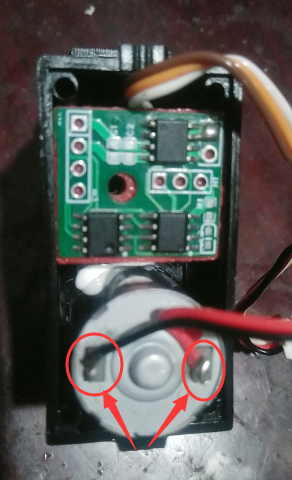
## Physical Demonstration The servo I bought has a potentiometer fixed with a screw with a large flat washer
.
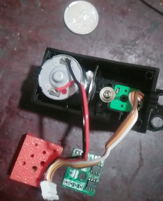
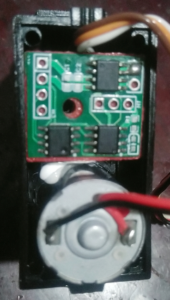
To avoid short circuits when the circuit board contacts the screw, I 3D printed a spacer. You can use other insulating materials instead. My insulating pad is installed as shown in the picture below. Then tighten a screw to fix it. My soldering is terrible, so please bear with it. I didn't want to spend money on SMT. After all, low cost is always my design theme.
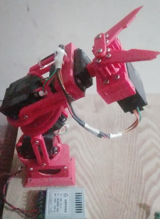
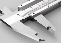
The ultimate goal of making this servo is to complete the following thing, which I think I'll call a robotic arm. Of course, this is just a basic one and can't compare to finished robotic arms. It's just for fun, to master some knowledge. Normal robotic arm grippers are not like this. They cost 13 yuan online, but I couldn't afford it, so I designed one myself. What does it look like? Actually, it's designed based on calipers.

## Precautions
When soldering for the first time, since it's unknown whether the servo's rotation direction and the potentiometer feedback signal direction are consistent, it's best to have a quick-connect switch on the servo power supply during the experiment. If the direction is indeed incorrect, simply swap the two wires on the motor.
## About the demonstration video (Let my mechanical hand do a couple of taps; I haven't actually developed any decent host computer software yet. I only sent four commands using STC's serial port assistant, just to prove that the servo program works.)
Note that this article is not a tutorial on how to build a robotic arm. My demonstration uses a robotic arm to show you what my servo motor can do, and to prove that the servo motor program and circuitry are effective and usable. My robotic arm is not yet perfect; its movements are still very uncoordinated, and most importantly, it's top-heavy. Various dimensions also need modification, so I do not recommend imitating it. ## The source code and firmware are in the attachments. Feel free to leave comments and discuss any questions; let's have some fun together! When making the PCB
, be sure to follow your servo motor's dimensions and modify it accordingly. My circuit is simple, with only a few wires; just make sure the power wires are thick. Don't rush to place an order; I've never been able to use someone else's files directly, and it was all a waste. I bought 10 servos, made 6, and kept the other 4 for other DIY projects. ## Reflections After Project Completion It seems the servos are working properly now, but it has a drawback: all the servos can't move simultaneously, and the servo speed is too fast (the robotic arm moves too fast, it's scary, especially the large arm). We need to add a ramp acceleration/deceleration algorithm to its program. I feel it's necessary to make a teach pendant to guide its operation in the future. My next steps are: 1. Make a teach pendant; 2. Modify the protocol to allow all servos to move simultaneously; 3. Add a ramp algorithm to control the movement speed. Of course, these are problems to be solved in the next project .
Akai No. 1 Development Board
This development board is based on the STC32G12K128-LQFP48 and includes some onboard hardware, making it usable as a minimal system.
A rotary table is being built here, which requires a 3D-printed component.
This design draws inspiration from the open-source project of the STC32G12K128 minimum system. While retaining all the pin headers, it adds various peripherals, including an OLED display, an MP3 playback module, a buzzer circuit, a stepper motor drive circuit, four tactile buttons, and an RGB light.
Currently, it serves two purposes: first, a calculator capable of various calculations with audible feedback and MP3 prompts; second, a rotating platform that measures and displays weight via an HX711 module while allowing the control panel to rotate at different angles or in different ways.
The 3D printing and software components will be further developed and open-sourced later.
This design is a core functional board based on the STC32G12K128-LQFP32 microcontroller. All I/O pins are brought out, and it is equipped with the most basic and practical peripheral components. It is excellent whether used as a standalone development board or inserted into a baseboard to expand into a product.
This is a core board based on the STC32G12K128-LQFP32 microcontroller. It retains basic resources and features the following:
All I/O pins are brought out via headers; some out-of-order I/O pins have been grouped and sorted;
it has a USB-TYPE-C interface for USB development, debugging, and downloading;
it has a one-key cold restart function, which can replace reset;
it has one external interrupt that also triggers USB HID Wirter programming mode; it
has a TL431 external 2.5V reference source;
it has a power indicator and two I/O control LEDs, multiplexed with PWM4, also serving as PWM output indicators;
it has an external small-capacity I2C interface; it has an EEPROM;
it has a 3.3V LDO, selectable between 5V and 3.3V power supply via jumpers at the header, allowing for external power supply or its own power supply;
it has 5V TVS protection on the power port; it has ESD protection
for the USB interface; it has a self-resetting fuse for overcurrent protection on the power port;
it has an optional 32768Hz crystal for easy debugging; the internal RTC
is in a wide-body 36-pin package with 800mil spacing, does not support movable sockets, and is compatible with breadboards.

 the STC8G1K08A controller used in Stephen Chow's film "From Beijing with Love," which is low-cost and has all I/O ports routed to LEDs.
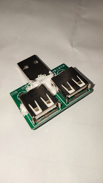
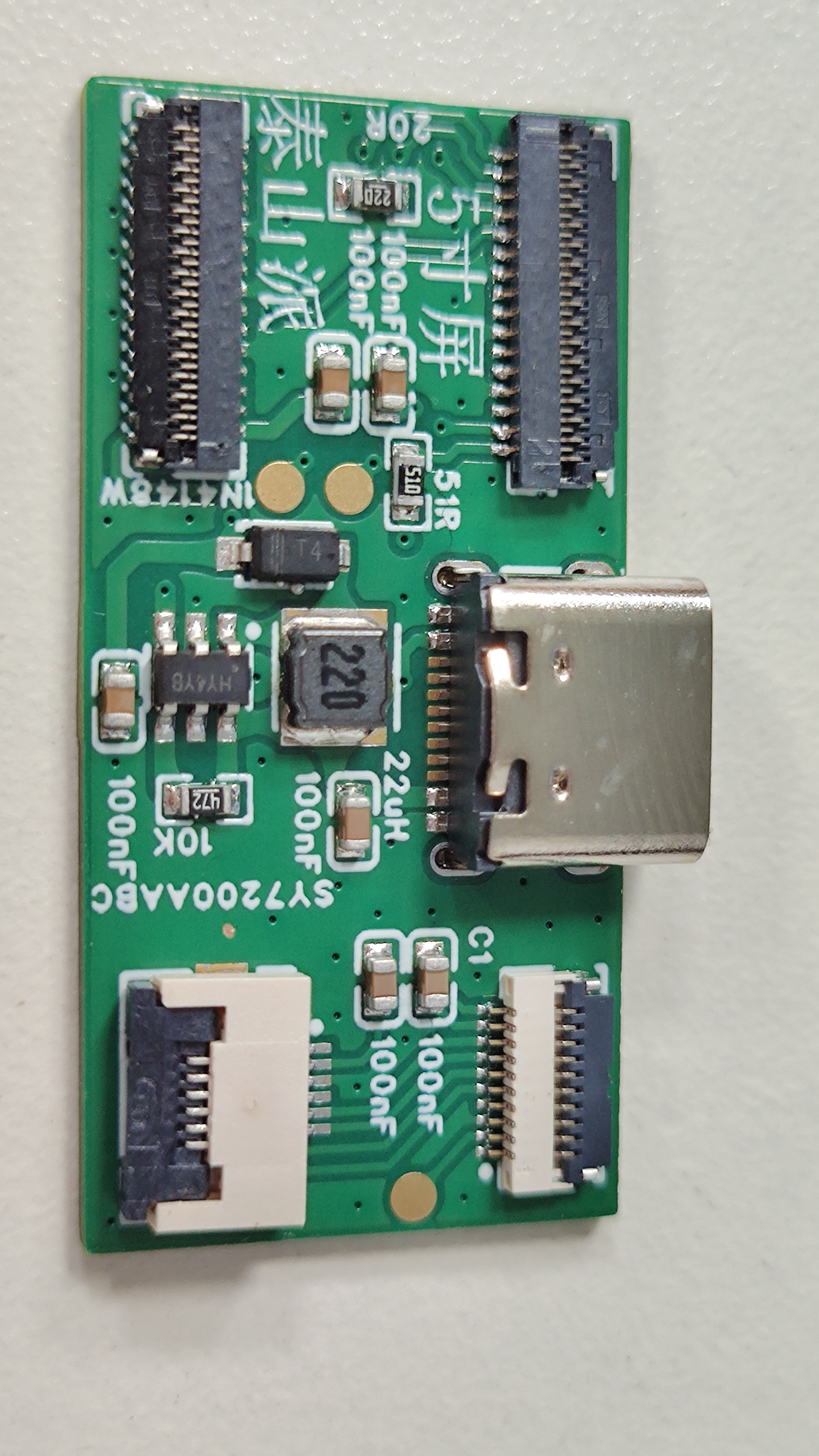
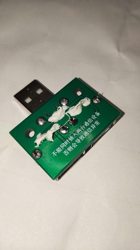 The inspiration for this product design came from the fact that a home switch panel had two servo motors for control. Each servo motor only draws 300mA of current, so plugging in two chargers with 1A current would be wasteful. Therefore, a USB splitter was designed so that only one charger is needed to power both servos.


 京公网安备 11010802033920号

 LPI3124A114721


