I. Function Introduction
Final Program Code Functions:
LED1 displays the power-on status (solid on), LED2 displays the button mode (mode 0 solid on, modes 1, 2, 3, 4 flashing).
K1 button switches display modes, K2 button sets the parameter value for the corresponding mode and saves it to FLASH (for calibration), K3 button returns to mode 0.
Two 3-digit LED displays show the current voltage (upper) and current (lower) values.
Mode Descriptions:
Mode 0: Displays normal voltage and current values (upper row displays voltage, lower row displays current)
. Mode 1: 5V voltage calibration setting. The upper row displays V.05. The lower row displays the current voltage value. In this mode, the multimeter should be set to 5.00V to measure the measured digit. Pressing K2 calibrates the current value to 5V.
Mode 2: 15V voltage calibration setting. The upper row displays V.15. The lower row displays the current voltage value. In this mode, the multimeter should be set to 15.0V to measure the measured value. After pressing the K2 key, the current value is calibrated to 15V.
Mode 3: Current 0.5A calibration setting. The upper row of the digital tube displays A.0.5. The lower row displays the current current value. After pressing the K2 key, the current value is calibrated to 0.5A.
Mode 4: Current 1.5A calibration setting. The upper row of the digital tube displays A.1.5. The lower row displays the current current value. After pressing the K2 key, the current value is calibrated to 1.5A.
II. Assembly Instructions (PCB + Component Soldering + 3D Shell + Panel)
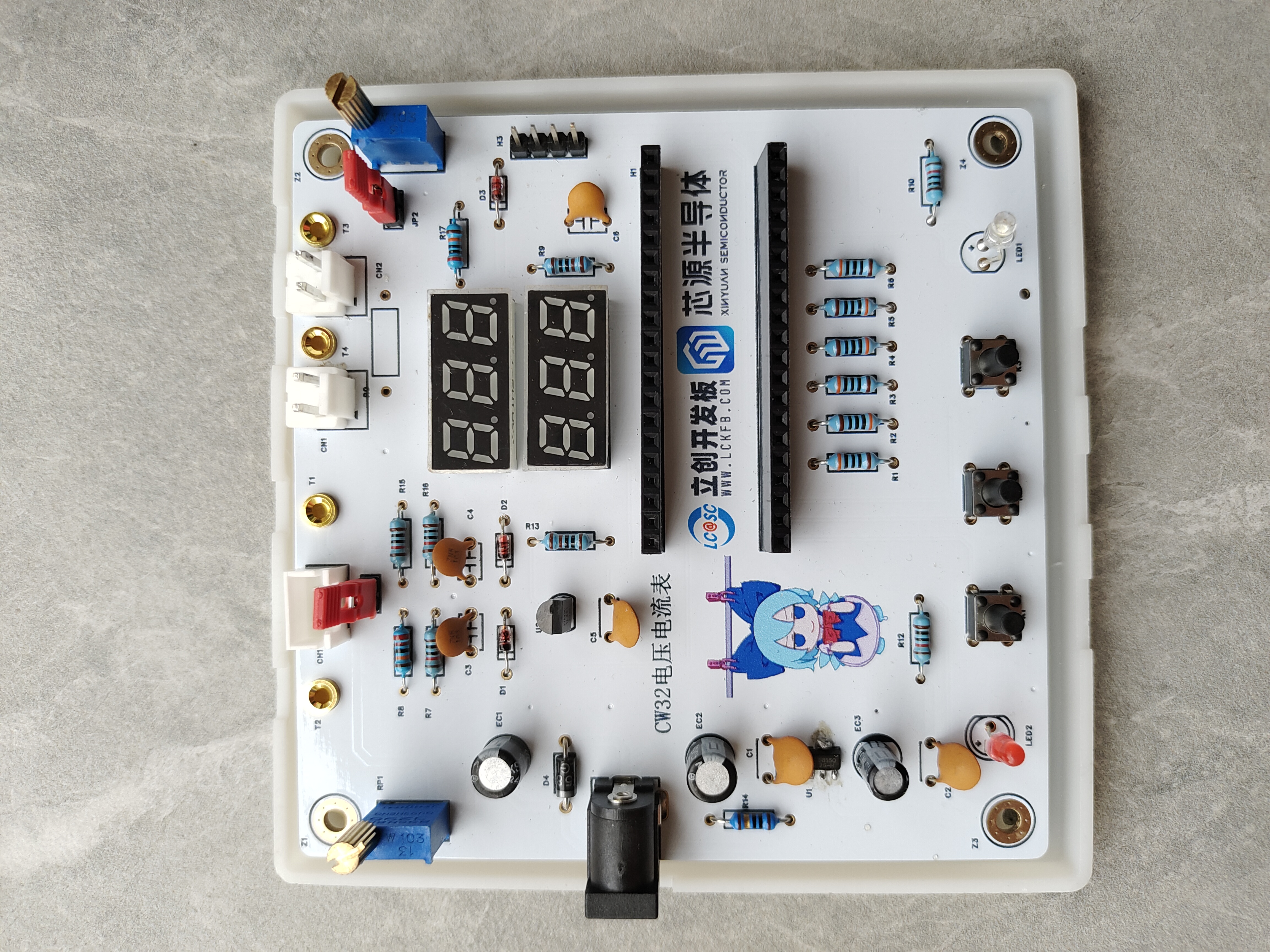
Solder each component on the PCB according to the schematic diagram and the silkscreen printing on the board. Pay attention to the orientation of the diodes and aluminum electrolytic capacitors to avoid cold solder joints.
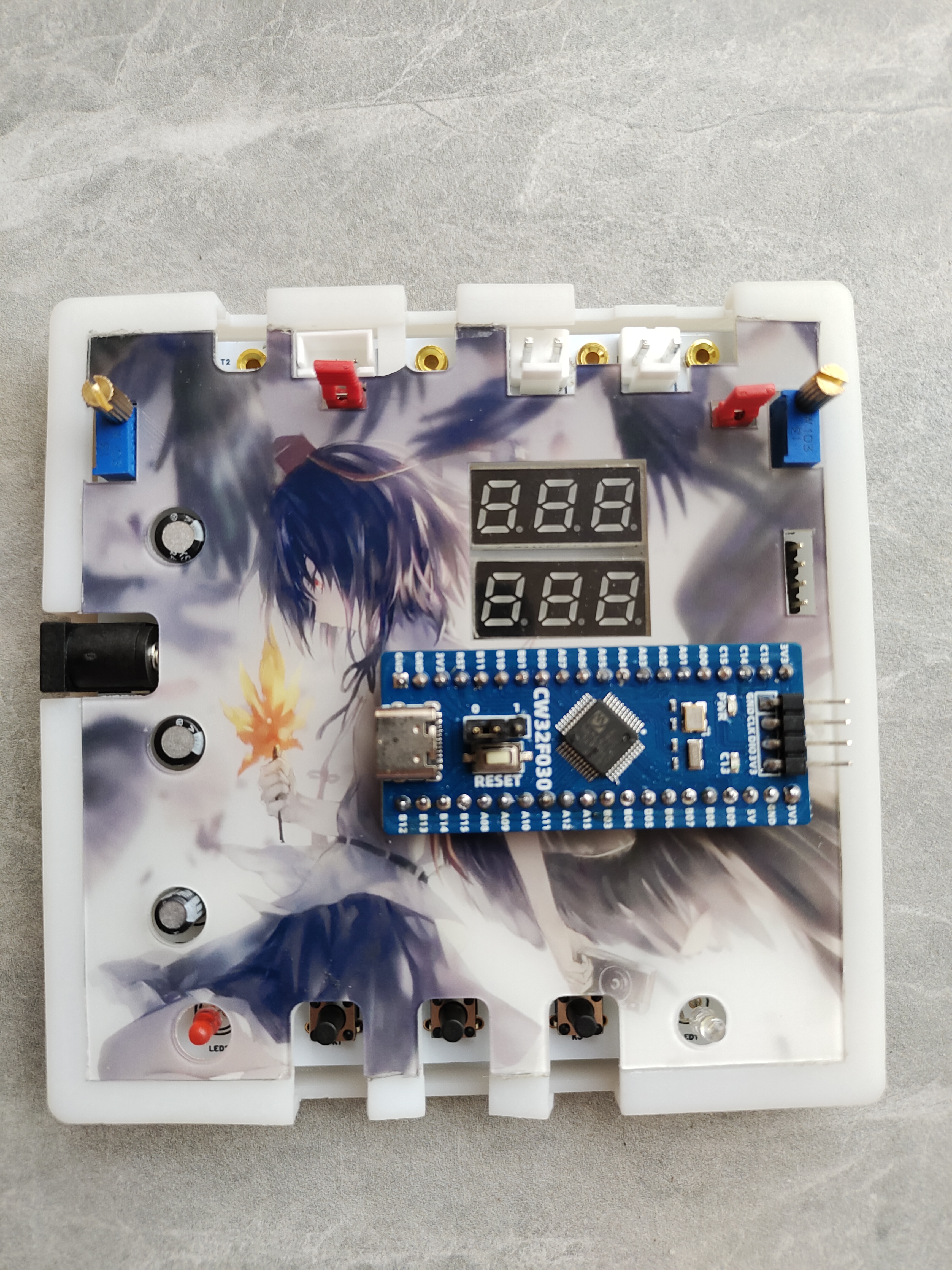
After soldering, install the 3D shell. There are screw holes on the bottom; tighten the screws at the four corners to secure it.
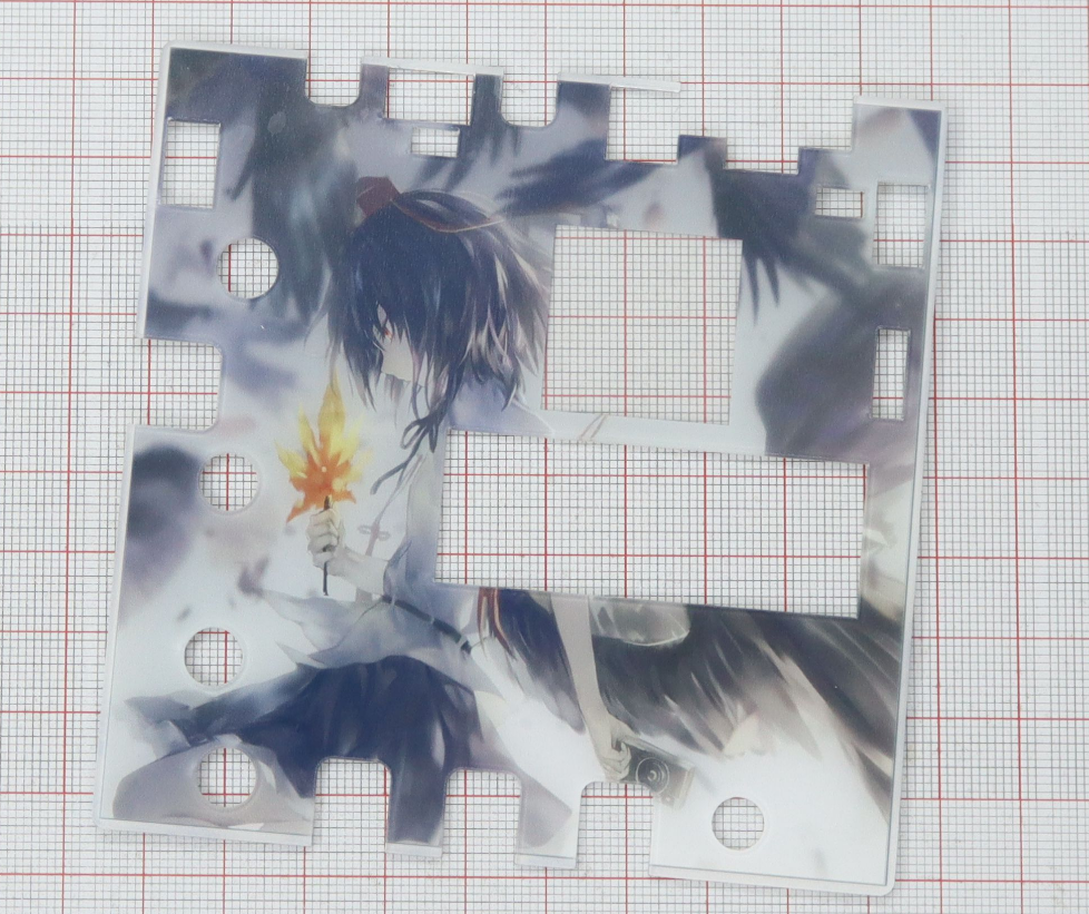
Finally, attach the panel to complete the assembly.

Finished product.
III. Hardware Design
1. Power Supply Circuit
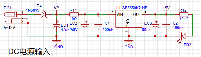
LDO (Low Dropout Linear Regulator) Selection
This project uses an LDO as the power supply. Considering that most voltmeter products are used in industrial scenarios with 24V or 36V power supplies, the SE8550K2 with a maximum input voltage of up to 40V was selected as the power supply. The main reason for not using a DC-DC step-down circuit to handle the large voltage drop is to avoid introducing ripple interference from the DC-DC circuit during the design process; a secondary reason is to reduce project costs.
Summary: The capacitors surrounding the LDO play an important role in filtering, improving load transient response, phase compensation, preventing oscillation, ripple suppression, and controlling startup surge current. By properly configuring these capacitors, the stability and performance of the LDO circuit can be ensured.
In the power supply design of this project, electrolytic capacitors and ceramic capacitors are connected in parallel in sequence. When electrolytic capacitors and ceramic capacitors are connected in parallel, they can be "matched in high and low frequencies," giving the circuit good filtering performance in both high and low frequency regions. Electrolytic capacitors filter out low-frequency interference, while ceramic capacitors filter out high-frequency interference; the combination of the two can achieve better filtering results.
2. MCU Selection Analysis
To reduce learning costs, this project uses the LCSC CW32F030C8Tx development board (core board) as the main controller.
Avoid blind selection.
When selecting the MCU (microcontroller unit) for this project, multiple aspects need to be considered to ensure the chosen MCU meets the project requirements.
Clearly define your project requirements: Understand the required computing power, including clock speed, processor core type, and whether a floating-point unit is needed.
Clearly define the required I/O ports and important peripherals, such as ADC peripherals. Since this is a development board project, the main purpose is debugging and learning; therefore, there are no strict limitations on the number of I/O ports: i.e., the associated costs are not considered.
Key advantages of CW32 in this project
: Wide operating temperature range: -40~105℃;
Wide operating voltage range: 1.65V~5.5V (STM32 only supports 3.3V systems);
Strong anti-interference: HBM ESD 8KV; All ESD reliability reaches the highest international standard level (STM32 ESD 2KV)
; Project focus - Better ADC: 12-bit high-speed ADC, achieving ±1.0LSB INL 11.3ENOB; Multiple Vref reference voltages... (STM32 only supports VDD=Vref);
Stable and reliable eFLASH technology.
ADC Sampling:

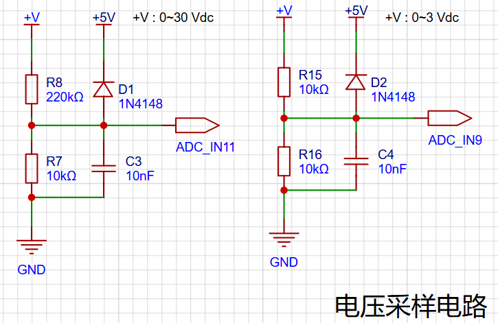
3. Voltage Sampling Circuit:
This project uses a voltage divider circuit to achieve high voltage acquisition, designed to acquire voltages up to 100V, currently configured to acquire voltages from 0-30V.
The voltage divider resistors in this project are designed to be 220K+10K, therefore the voltage division ratio is 22:1 (ADC_IN11).
The voltage divider resistor selection
is based on the maximum measured voltage; for safety reasons, this project uses 30V (the actual maximum display value can be 99.9V or 100V).
The ADC reference voltage in this project is 1.5V, which can be configured through the program.
To reduce power consumption in the sampling circuit, the low-side resistor (R7) is usually selected as 10K based on experience.
The high-side resistance of the voltage divider resistors can then be calculated using the above parameters.
The required voltage division ratio is calculated as follows: ADC reference voltage: Design input voltage, calculated using known parameters as 1.5V/30V=0.05.
The high-side resistance is calculated as: Low-side resistance/voltage division ratio, calculated using known parameters as 10K/0.05=200K.
A standard resistor is selected: A resistor slightly higher than the calculated value is chosen; the calculated value is 200K. We usually choose E24 series resistors, therefore in this project, 220K is selected, which is greater than 200K and closest to the calculated value.
Note:
If the voltage to be measured is lower than 2/3 of the module's design voltage (66V) in actual use, the voltage divider resistor can be replaced and the program modified to improve measurement accuracy.
If the voltage to be measured is higher than the module's design voltage of 99V, the voltage divider resistor can be replaced or the reference voltage can be modified to achieve a larger voltage measurement range.
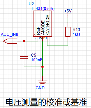
This project adds a TL431 circuit to provide a 2.5V reference voltage, which can be used to provide an external voltage reference for calibrating the AD converter.
Additionally:
Diode clamping ensures MCU safety: A 1N4148 (D1, etc.) was added to the sampling circuit as a clamping diode to avoid damage to chip pins due to incorrect voltage input during learning and debugging.
Considering the potential fluctuations in the measured power supply, a 10nF filter capacitor was connected in parallel with the low-side voltage divider resistor to improve measurement stability.
A voltage sampling circuit was added to enable range switching: If the measured voltage is within 0~3V, the ADC_IN9 channel is used for measurement. At this point, due to the reduced voltage division ratio, the measurement accuracy is greatly improved.
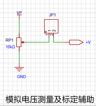
4. Circuits used for simulating voltage measurement, measurement calibration, and measurement calibration aids.
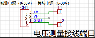
The components T1 and T2 are 2mm banana plug connectors on the development board, used to connect multimeter probes. Multimeter or high-precision benchtop digital multimeter probes can be inserted to verify the accuracy of the development board's measurements. Alternatively, 2mm banana plug multimeter probes can be inserted to replace the CH1 port for handheld measurements.
The VP pin is the development board's power supply pin and should not be connected when using the DC port. When not using DC port power and the measured value is greater than 5V and less than 30V, the power supply under test can be connected, or it can be powered independently.
Considering that users may not be able to easily build peripheral circuits for testing and debugging, and adhering to the principle of ease of development, auxiliary circuits for simulating voltage measurement, measurement calibration, and measurement calibration are provided. No external voltage is required for CH1. Use the multi-turn adjustable potentiometer (RP1) to divide the development board's power supply voltage and connect it to the +V network through the development board's internal circuitry. Note that JP1 needs to be shorted at this time; a jumper cap is sufficient, and a long-handled jumper cap is recommended. Do not short JP1 if this function is not used.
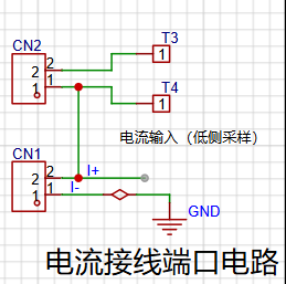
5. Current Sampling Circuit:
This project uses a low-side current sampling circuit for current detection.
When learning, do not solder R0 when the low-side of the sampling circuit shares a common ground with the development board's meter interface!

Voltage Divider Resistor Selection:
The sampling current designed for this project is 3A, and the selected sampling resistor (R0) is 100mΩ.
The selection of the sampling resistor mainly needs to consider the following aspects:
the maximum value of the pre-designed measurement current; in this project
, the voltage difference caused by the 3A current sensing resistor should generally not exceed 0.5V;
the power consumption of the current sensing resistor should be selected based on this parameter. Considering the power consumption (temperature) issue under high current, a 1W packaged metal wire-wound resistor was selected.
Voltage amplification factor of the current sensing resistor: This project does not use an operational amplifier to build an amplification circuit, so the factor is 1.
The current sensing resistor value can then be calculated using the above parameters. Selection:
Since this project does not use... The amplifier circuit requires a larger sampling resistor to obtain a higher measured voltage for measurement.
Considering that a larger resistor would result in a larger voltage drop and higher power consumption, an unlimited selection of a larger resistor is not advisable.
This project uses a 1W package resistor, corresponding to a temperature rise power of 1W.
Based on the above data, a 100mΩ current sensing resistor was selected. According to the formula, 3A * 100mΩ = 300mV, 900mW can be calculated.
Additionally,
the clamping diode and
capacitor
have similar functions. R9 has multiple uses, primarily current limiting and MCU protection. It may also form an RC resonant circuit with the capacitor, affecting the circuit. Please refer to the tutorial for details.
6. Auxiliary circuits for simulating current measurement, calibration, and measurement adjustment.
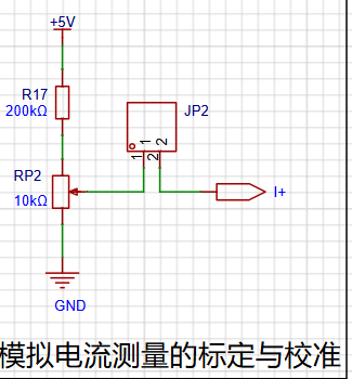
Note that the wiring will differ. When R0 is not soldered, RP2 is equivalent to R0, replacing R0 to divide and collect voltage information, which is then converted into a current value by software.
Do not solder the R0 sampling resistor when using this function. Disconnect JP2 if this function is not used.
7. Digital tube driver.
This project uses a digital tube as the display unit.
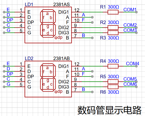
This project uses two 0.28-inch three-digit common-cathode LED displays as the display device. Compared to a display screen, LED displays offer better visibility in complex environments. The brightness of the LED displays can be increased by using smaller current-limiting resistors, depending on the specific needs of the application environment. Furthermore, LED displays have better mechanical properties and are not as easily damaged by external forces as display screens. They are widely used in industrial applications where stability and reliability are crucial. From a development board learning perspective, this makes it easier to learn electronic measurement principles and related development in a targeted manner.
In this project, actual testing showed that the current-limiting resistors (R1~R6) for the LED displays were configured to 300Ω. The corresponding brightness for both red and blue LED displays was good and the brightness was soft and not glaring.
Strictly speaking, the current-limiting resistors should be added to the segments; adding them to the digits would affect the display effect. Our actual design places them in the digits to save a few resistors, but the impact on the display is not significant. Therefore, we add them to the digits for convenience.
The
driving principle of LED displays mainly involves controlling the switching state of each segment of the LED display to display numbers, letters, or symbols. The following is a detailed explanation of the driving principle:
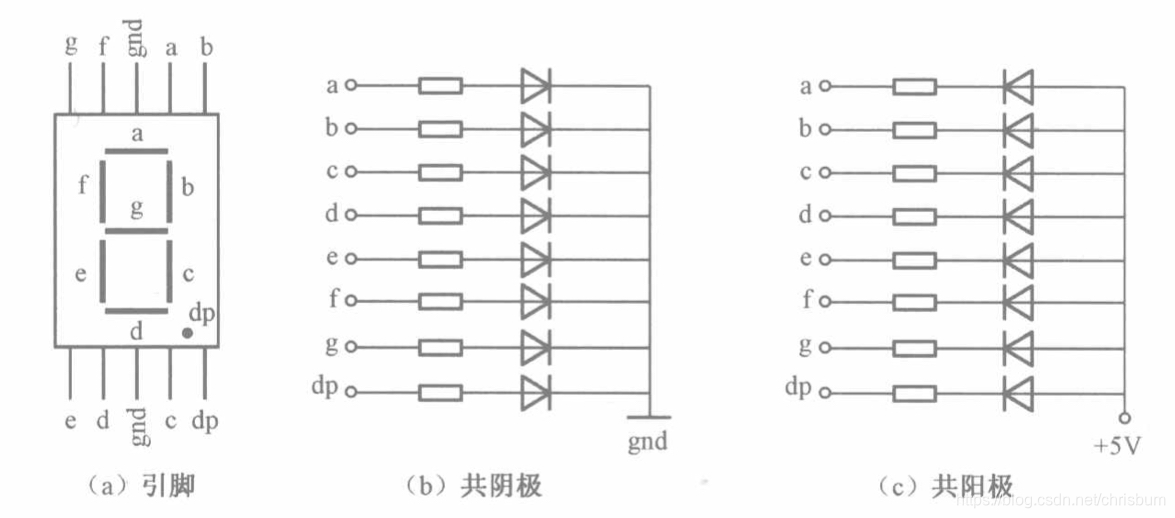
Basic Structure of a Digital Tube:
A digital tube typically consists of seven or eight LED segments (eight segments in this project). Each segment represents a part of the digital tube and can display numbers 0-9, letters AF, etc.
Digital tubes come in two types: common cathode and common anode. The difference lies in whether the common terminal COM (the end connecting all LEDs) is connected to the negative or positive terminal of the power supply.
Driving Methods:
Segment Selection: The desired number or character is displayed by controlling the on/off state of each segment of the digital tube. Each segment corresponds to a control signal; when the control signal is on, the segment lights up, and vice versa. (a, b, c, d, e, f, g, dp)
Bit Selection: The digital tube to be displayed is selected by controlling the bit lines of the digital tube. Bit line control sets the bit line of the digital tube to be displayed to a high level, and the bit lines of other digital tubes to a low level. By continuously switching the state of the bit lines, the display switching between multiple digital tubes can be achieved.
Driving Circuit:
The driving circuit for a digital tube can be implemented using hardware circuits, such as integrated circuits like digital signal processors (DSPs), microcontrollers (MCUs), or shift registers, to generate control signals suitable for the LEDs.
These control signals can be in the form of pulse width modulation (PWM) signals, serial data signals, etc. By controlling the frequency, width, and amplitude of these signals, the brightness of the digital tube can be controlled, thereby displaying the desired numbers or letters.
Software Control:
In addition to hardware driving circuits, the driving of digital tubes can also be implemented through software control. By programming to generate control signals suitable for the digital tubes, more flexible and complex display effects can be achieved, such as scrolling or alternating display of numbers.
Driving Common Cathode and Common Anode Digital Tubes:
For common cathode digital tubes, the common cathode pin is connected to the negative terminal of the power supply, and the control pin is connected to the output pin of the control chip. When a certain number needs to be displayed, the control chip outputs the corresponding encoded signal to the control pin, causing the corresponding LED segment to light up.
For common anode digital tubes, the working principle is similar to that of common cathode digital tubes, except that the common anode pin is connected to the positive terminal of the power supply, and the control pin is connected to the output pin of the control chip.
Encoded Display:
In order for the digital tube to display the corresponding numbers or characters, the segment data port must output the corresponding character encoding. For example, to display the number "0", the character code for a common anode seven-segment display is 11000000B (i.e., C0H), while the character code for a common cathode seven-segment display is 00111111B (i.e., 3FH). The specific code depends on the actual seven-segment display.
Dynamic and Static Display:
Seven-segment displays can use either static or dynamic display methods. In static display, each of the eight segments of a seven-segment display is connected to an 8-bit I/O port address. As long as the I/O port outputs a segment code, the corresponding character is displayed and remains unchanged. Dynamic display, on the other hand, lights up each segment of the seven-segment display one by one in turn, achieving simultaneous visual display through rapid switching.
In summary, the driving principle of a digital tube is to display numbers, letters, or symbols by controlling the switching state of each segment of the digital tube, and to switch between multiple digital tubes through segment selection and digit selection. Simultaneously, the driving of the digital tube can be achieved through hardware circuits or software control, and common cathode or common anode digital tubes can be selected for driving as needed.
This project actually uses dynamic scanning display to drive the digital tube.
Calculating the required current for the digital tube :
Since this project uses dynamic scanning display to drive the digital tube, at any given time, only a maximum of 8 segments of the digital tube (or LEDs) can be lit, or in other words, only one digit can be lit. According to the design, the required driving current is approximately 11mA (IO port high-level voltage 3.3V ÷ 300Ω).
8. LED Indicator Lights:
This project additionally designed a power indicator light and an IO working indicator light.
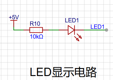
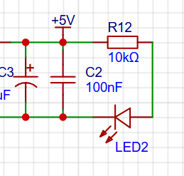
Since the sinking current capability of chip I/O is often greater than its sourcing current capability, LED1 is designed to be I/O low-level active (on).
To reduce the current consumption of the LED, some LED brightness is sacrificed, the type of component parameters is reduced, and the current-limiting resistor for the LED is selected as 10K.
9. Button Circuit Design
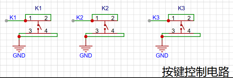
There are multiple design methods for button control circuits. Thanks to the CW32's internal I/O ports which can be configured with pull-up and pull-down resistors, the button control circuit on the chip's periphery does not require configuration. One end of the button is connected to the MCU's I/O, and the other end is grounded. When the button is pressed, the I/O is pulled low. IV
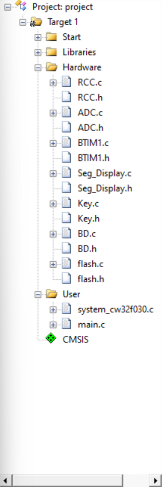
. Software Design
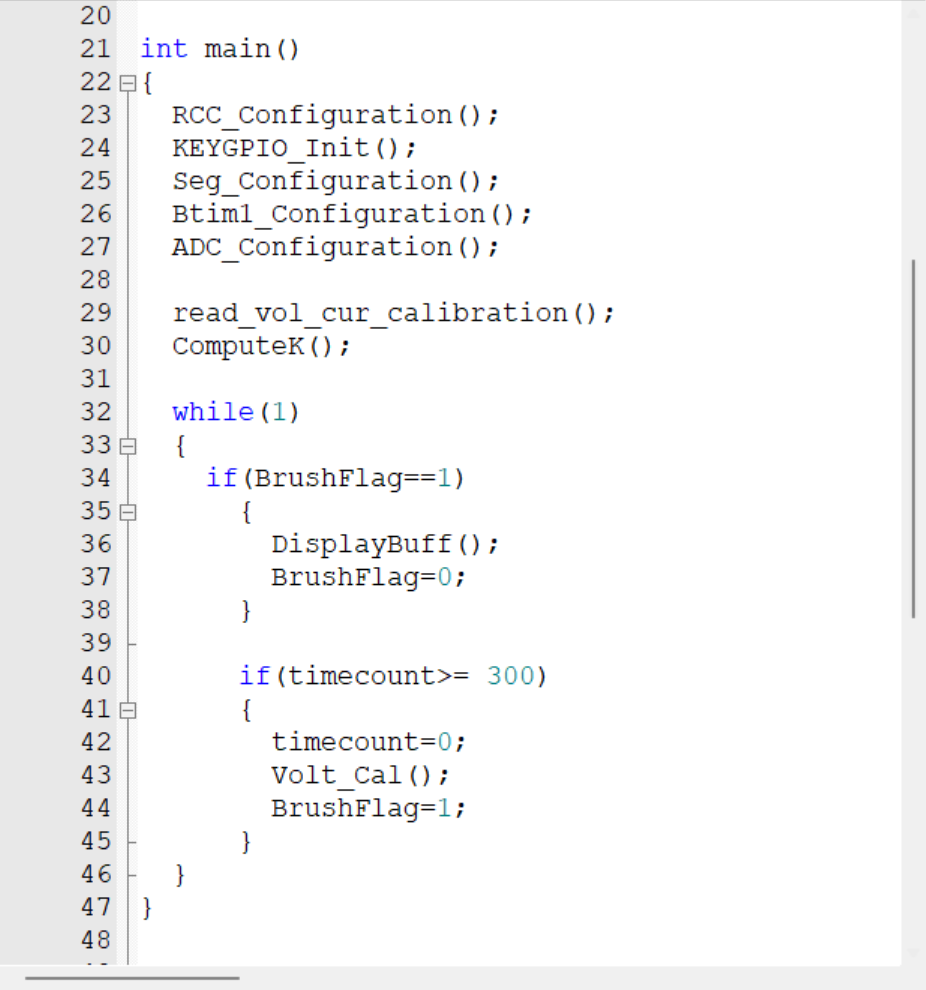
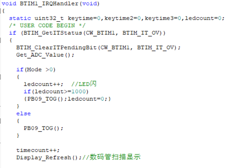
This section only discusses the final code; other code is the basis or a summary of the final version. 1. Development Board Environment Setup: 1) Install Keil and crack the software. 2) Install the CW32 pack and import it into Keil. 3) Create a new project and import the startup file, etc. 2. Explanation of Important Parts of the Final Code (in the order of program logic): Modular Program. 1) In the main function, RCC clock initialization, button initialization, digital tube initialization, Timer 1 initialization, and ADC initialization are performed. (Download the code for each initialization function directly; it is not shown here due to the large number of functions.) 2) Once the timer is configured and enabled, and the timer interrupt is configured and enabled, the timer starts counting. Whenever the configured time is reached, the program jumps to the interrupt execution function, triggering once every 1ms. 3) The first if function checks and clears the interrupt flag, then enters the interrupt function for execution. 4) The Get_ADC_Value() function retrieves the raw data sampled by the ADC (the data is not yet converted by software). Within this function, ADC_GetSqr0Result(&Volt_Buffer[adc_cnt]); and ADC_GetSqr3Result(&Curr_Buffer[adc_cnt]); access the corresponding ADC registers to obtain the raw data sampled by the corresponding ADC, storing it in the array enclosed in parentheses. The subsequent if functions specify 100 samplings, and ADC_SAMPLE_SIZE is defined as a macro. 5) Display_Refresh() scans and displays the data on the digital tube. The function Seg_Dis(num bit selection, Seg_Reg[num] segment selection) displays numbers, letters, or symbols, where Seg_Reg[num] is an array (this function is important; understand it clearly). 6) After timecount++ to >=300, return to the main function to execute the Volt_Cal() function to calculate the actual voltage and current values. This function requires the DisplayBuff(), DisplaySETV(), Display(), and DisplayI() functions to work together to calculate the results and scan and display them (the logic needs to be carefully understood). Volt_Cal(void) { float t,KT1; V_Buffer = Mean_Value_Filter(Volt_Buffer,ADC_SAMPLE_SIZE); I_Buffer = Mean_Value_Filter(Curr_Buffer,ADC_SAMPLE_SIZE); if(V_Buffer>=X05) { t=V_Buffer-X05; V_Buffer=(K*t+Y05)*1000;} else { KT1=5000; KT1=KT1/X05; V_Buffer=KT1*V_Buffer; } if(V_Buffer % 10 >= 5) { V_Buffer = V_Buffer / 10 + 1; } else { V_Buffer = V_Buffer / 10; } if(I_Buffer>=IX05) { t=I_Buffer-IX05; I_Buffer=(KI*t+IY05)*10; } else { KT1=500; KT1=KT1/IX05; I_Buffer=KT1*I_Buffer; } if(I_Buffer % 10 >= 5) { I_Buffer = I_Buffer / 10 + 1; } else { I_Buffer = I_Buffer / 10; } }


The `Mean_Value_Filter()` function is the filtering function, while the `V_Buffer` and `I_Buffer` arrays store the raw ADC data obtained from the `Get_ADC_Value()` function in step 4). After filtering, the following `if` and `else` functions convert the raw voltage and current data (to the desired voltage and current values) and perform rounding (theoretically calibrated, and later, the actual calibrated values). Finally, the values are assigned back to the `V_Buffer` and `I_Buffer` arrays.
The theoretical values of `K`, `KI`, `X05`, `IX05`, `X15`, and `IX15` are calculated in the following functions: `ComputeK()` and `read_vol_cur_calibration()` are already executed in the main function.
void ComputeK(void) // Calibration code calculates the slope function, the variable with Y has been initialized and assigned
{
K=(Y15-Y05);
K=K/(X15-X05);
KI=(IY15-IY05);
KI=KI/(IX15-IX05);
}
void save_calibration(void) // Calibration storage function
{
uint16_t da[5];
da[0]=0xaa;
da[1]=X05;
da[2]=X15;
da[3]=IX05;
da[4]=IX15;
flash_erase();
flash_write(0,da,5);
}
void read_vol_cur_calibration(void)
{
uint16_t da[5];
flash_read(0,da, 5);
if(da[0]!= 0xaa) // Not calibrated yet, calculate the theoretical value and store
{
X15=15.0/23/1.5*4096;
X05=5.0/23/1.5*4096;
IX05=0.5*0.1/1.5*4096;
IX15=1.5*0.1/1.5*4096;
save_calibration();
}
else
{
X05=da[1];
X15=da[2];
IX05=da[3];
IX15=da[4];
}
}
7) After BrushFlag is set to one in the main function, the DisplayBuff() function is executed.
void DisplayBuff(void)
{
if(Mode==0)
{
Display(V_Buffer);
if(I_Buffer>400)I_Buffer=400;
DisplayI(I_Buffer);
}
else if(Mode==1) //V.05.
{
Seg_Reg[0] =21;
Seg_Reg[1] =0;
Seg_Reg[2]=5+10;
DisplaySETV(V_Buffer);
}
else if(Mode==2) //V.15.
{
Seg_Reg[0] =21;
Seg_Reg[1] =1;
Seg_Reg[2]=5+10;
DisplaySETV(V_Buffer);
}
else if(Mode==3) //A.0.5
{
Seg_Reg[0] =20;
Seg_Reg[1] =0+10;
Seg_Reg[2]=5;
DisplayI(I_Buffer);
}
else if(Mode==4) //A.1.5
{
Seg_Reg[0] =20;
Seg_Reg[1] =1+10;
Seg_Reg[2]=5;
DisplayI(I_Buffer);
}
}
void DisplaySETV(uint32_t value)
{
uint8_t Thousands;
uint8_t Hundreds;
uint8_t Tens;
uint8_t Units;
Thousands = value / 1000;
if(Thousands > 0)
{
Units = value % 10;
value = Units > 5 ? (value + 10) : value;
Thousands = value / 1000 % 10
; Hundreds
= value / 100 % 10
;
Tens = value / 10
% 10; Tens;
}
else
{
Units = value % 10;
Tens = value / 10 % 10;
Hundreds = value / 100 % 10
; Seg_Reg[3] = Hundreds + 10 ;
Seg_Reg [
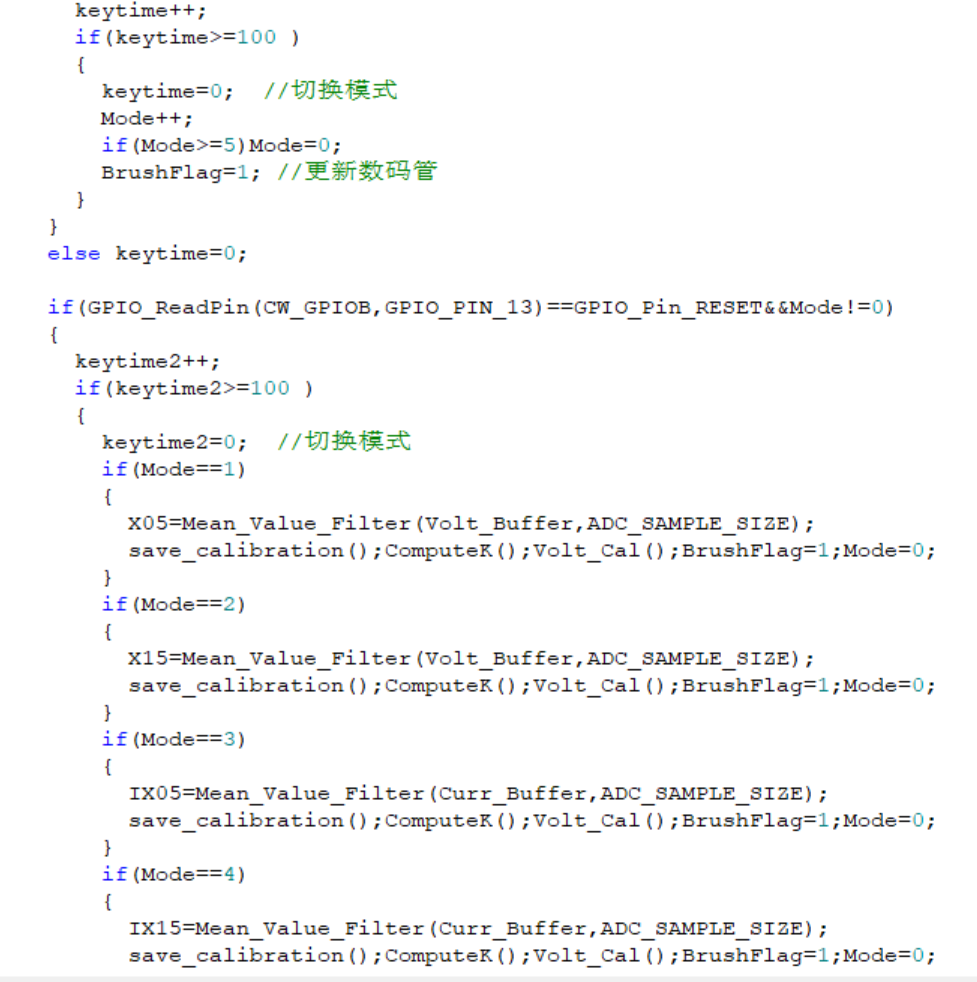
4 ] = Tens ; Hundreds; uint8_t Tens; uint8_t Units; Thousands = value / 1000; if(Thousands > 0) { Units = value % 10; value = Units > 5 ? (value + 10) : value; Thousands = value / 1000 % 10; Hundreds = value / 100 % 10 ; Tens = value / 10 % 10 ; Seg_Reg[1] = Hundreds + 10; Seg_Reg[2] = Tens; } else { Units = value % 10; Tens = value / 10 % 10; Hundreds = value / 100 % 10; Seg_Reg [0] = Hundreds + 10 ; Seg_Reg[1] = Tens ; DisplayI(uint32_t value) { Seg_Reg[3] = value/100 + 10; Seg_Reg[4] = value%100/10; Seg_Reg[5] = value%10; } It is worth noting that the DisplayBuff() function contains three functions: DisplaySETV(), Display(), and DisplayI(). After processing the data, it is placed into the Seg_Reg[] array for display (divided into modes 0, 1, 2, 3, and 4, corresponding to the calibration function). 8) The above is roughly the main part of mode 0. Next, we will talk about calibration. It is necessary to switch modes 1, 2, 3, and 4 with the K1 button, calibrate with the K2 button, and return with the K3 button. This part is completed in the timer interrupt. Read the data and filter it. Store it with the da[] array and the save_calibration() function with the additional flsh function. Calculate the K value for calibration, display, and return to mode 0. Corresponds to the display function above. Note: Strengthen your understanding of the code logic yourself. For details, please refer to the (LCSC) project teaching materials (including hardware): https://wiki.lckfb.com/zh-hans/dwx-cw32f030c8t6/training/voltammeter-bootcamp/voltammeter.html V. PCB Description (See official documentation for details) For PCB design, once you understand the circuit schematic, the connection is relatively easy. Further wiring knowledge needs to be learned separately, as my wiring skills are not very good. VI. Material Purchase Besides the components listed in the BOM, you may also need the following: 1. You can buy long-handled potentiometers on Taobao, which are easier to adjust: [Taobao] https://m.tb.cn/h.gN1DCXxPYGZxN1u?tk=p2u234M82OP MF6563 "Metal Long-Handled 3296W Precision Multi-Turn Potentiometer 1K/2K/5K/10K Direct-Through Manual Adjustable Miniature Adjustable Resistor" Click the link to open directly or search on Taobao. 2. 3M screws: [Taobao] Limited-time offer: Buy 2 get 1 free https://m.tb.cn/h.gOwF6tTgkal7Mux?tk=KsTU34M9nQr HU9196 "304 Stainless Steel Phillips Flat Head Screws Countersunk Screws Small Machine Bolts M2 M2.5 M3 M4 M5 M6 M8 M10" Click the link to open directly or search on Taobao.
3.2mm Banana Socket: [Taobao] https://m.tb.cn/h.gOwvai7h3AHl497?tk=5Ogd34MkVsB CZ0002 "2mm Banana Socket Pure Copper Gold Plated K2A33 Socket 2mm Test Hole Circuit Experiment Teaching Instrument Circuit Board"
Click the link to open directly or search on Taobao.
4. Battery Power Supply: [Taobao] https://m.tb.cn/h.gmlvaPtyTH0azB6?tk=ZxHZ34MkbIS CZ3460 "~18650 Lithium Battery 3.7V 4.2V Charger for Flashlights, Small Fans, Microphones, Speakers, Radios, Headlamps (Universal)"
Click the link to open directly or search on Taobao.
5. Battery Box: [Taobao] https://m.tb.cn/h.gOwFqLfCVP6eRqy?tk=BlFT34MkKwu MF7997 "18650/26650 Battery Box PCB with Wire Switch SMD DIY Pin Socket Board Pins 1-Phase 2-Phase 3-Phase 4-Phase"
Click the link to open directly or search on Taobao.
6. Long-handled jumper caps: [Taobao] Limited time offer: ¥3 off orders over ¥60 https://m.tb.cn/h.gmdD4Mvny65zosj?tk=xFTR34Mll0a CZ0012 "Jumper caps, shorting caps, 2.54mm pitch, black, yellow, blue, red, shorting block pin headers, long-handled caps, connector caps"
Click the link to open directly or search on Taobao.
7. Two types of terminal wires: [Taobao] https://m.tb.cn/h.gOwwerylhS56l0S?tk=fCaM34Mlu0R CZ3452 "CH3.96mm pitch terminal wires 2P/3P/4P/5P/6P" "Single/Double-Head Electronic Wire Connection Harness"
Click the link to open directly or search on Taobao.
[Taobao] Limited-time offer: ¥3 off orders over ¥60 https://m.tb.cn/h.gOwDJkiIGqiOZoP?tk=U1Ak34Mln0p MF3543 "XH 2.54mm Terminal Wire 2/3/4/5/6P Male/Female Connector Wire Connection Cable 20/30CM"
Click the link to open directly or search on Taobao.
VII. LCSC Reference Materials (Refer to official materials for detailed explanations)
LCSC Hardware and Software Teaching Documents: https://wiki.lckfb.com/zh-hans/dwx-cw32f030c8t6/training/voltammeter-bootcamp/voltammeter.html
LCSC Bilibili Hardware and Software Teaching Videos: https://www.bilibili.com/video/BV1mw4m1r7Er/?spm_id_from=333.788


 京公网安备 11010802033920号

 10A06GP-BP-HF


