The CW32-based voltage and current meter tester from
Chipsource Semiconductor uses a minimum system board.
The CW32 chip typically supports high-precision voltage and current measurements, providing accurate data readouts and is suitable for applications requiring precise measurements. Wide measurement range: CW32 voltage and current meter testers generally cover a wide range of voltage and current measurements, ensuring effective operation under various testing requirements. Stability and reliability: Chipsource Semiconductor's chip design prioritizes stability and reliability, reducing measurement errors and enabling stable operation under various environmental conditions. High integration: CW32 chips typically integrate multiple functions, reducing the need for external components, simplifying circuit design, and improving the overall system integration and reliability. Low power consumption design: One of Chipsource Semiconductor's design principles is low power consumption; the CW32 chip enables efficient measurements with low power consumption, helping to extend battery life or reduce energy consumption. Ease of use and interface compatibility: The chip design typically considers user ease of operation, providing easy-to-integrate interfaces for convenient voltage and current measurement functions in various devices. With strong anti-interference capabilities, the CW32 chip typically possesses robust anti-interference capabilities, ensuring stable measurement results even in electromagnetic interference environments.
Hardware circuit schematic design
for digital tube display circuits

: Common cathode digital tube: In a common cathode digital tube, all cathodes are connected together, and the anode of each LED segment is controlled individually. By energizing a specific anode, the corresponding LED segment can be illuminated.
Display of numbers and letters: By appropriately controlling the current of each LED segment, numbers from 0 to 9, as well as some letters, can be displayed. For example, displaying the number "0" requires illuminating all segments, while displaying the number "1" only requires illuminating segments b and c, and so on. Circuit driving: The circuit for digital displays typically includes control logic and drivers. For each digital tube, appropriate control signals are needed to select the number or letter to be displayed and to transmit the appropriate current to the corresponding LED segment to ensure its brightness and display effect.
Multi-digit digital tube display: In cases of complex digital displays, multiple digital tubes are typically combined to form a multi-digit digital tube display. Each digital tube can be controlled independently, achieving complex display tasks by rapidly switching between displaying different numbers or characters.
Brightness Control: Some digital tubes also have brightness adjustment functions. The brightness of the LEDs can be adjusted by controlling the current or using PWM (Pulse Width Modulation) technology to adapt to different ambient light and display needs.
Applications: Digital tubes are widely used in calculators, electronic clocks, counters, dashboards, and other devices requiring digital display. They convey digital information simply and effectively and are widely accepted and used.
DC Power Input
Circuit Cold Start: This refers to the situation where, during initial startup or restart, the various components and parts in the circuit are at a low temperature or have been in a closed state for a long time. Therefore, special measures or designs are needed to ensure the circuit works normally. This situation usually affects some parameters and characteristics in the circuit, such as the voltage polarization state of capacitors and the operating point of transistors. Special initialization or activation steps are required before the circuit starts running to ensure that the circuit can work normally.
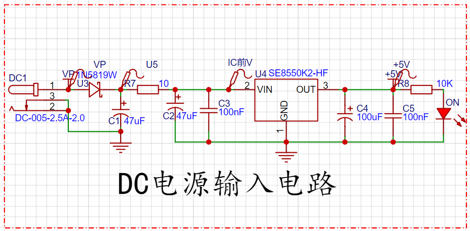
The DC power input circuit is mainly responsible for stably inputting external DC power into the circuit. This includes filtering, voltage regulation, and current protection to ensure that the power output meets the operating requirements of the equipment and prevent voltage and current instability from damaging the circuit. The SE8550K2 is typically used in switching control or amplification applications in power supply circuits. In DC power input circuits, it can be used as a current switch, load driver, or signal amplifier to help manage current flow and improve power supply stability. Its ultimate role in power management is to protect the circuit from overcurrent and voltage fluctuations. In voltage and current meter detectors,
the
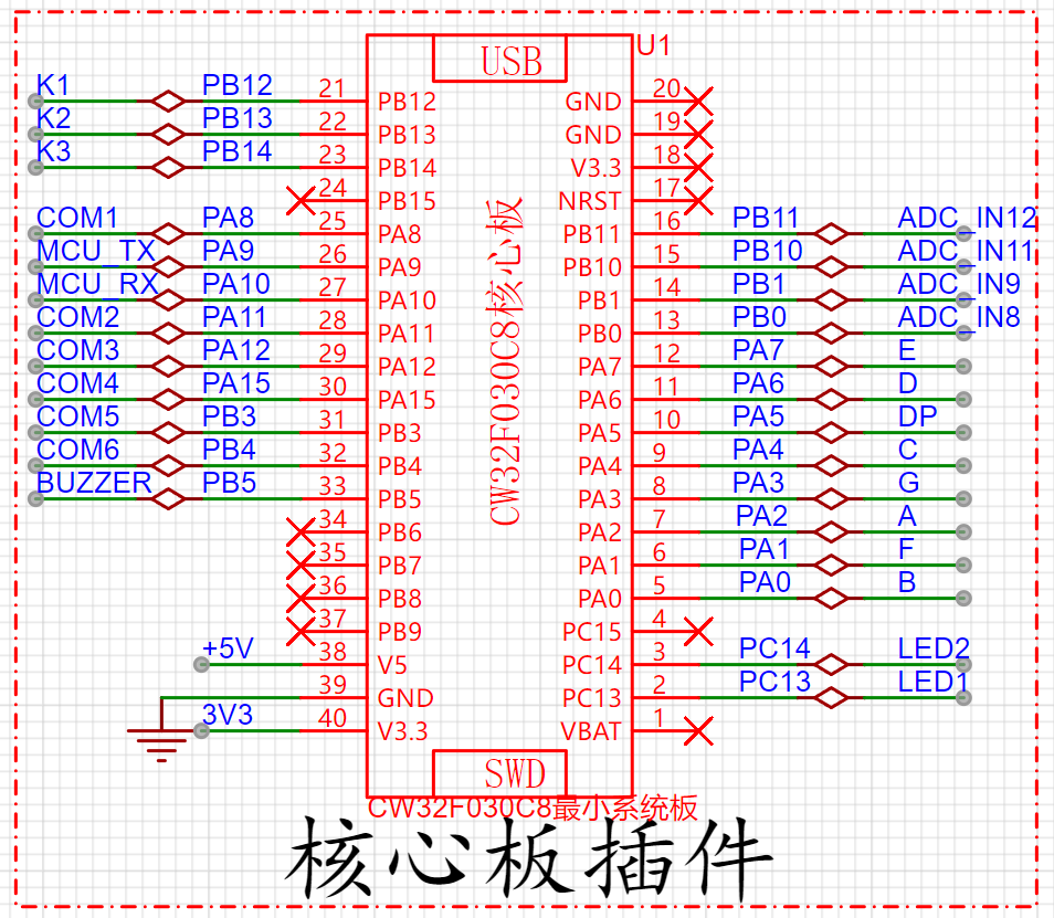
CW32F030 minimum core board typically handles data acquisition: the core board acquires voltage and current signals via a built-in analog-to-digital converter (ADC). It converts these analog signals into digital data for further processing. Signal processing: The microcontroller processes the acquired data, performing calculations and analysis using programmed algorithms to convert it into actual voltage and current values. This may include filtering, calibration, and measurement accuracy adjustment. Display and output: Measurement results are displayed to the user via serial port, LCD, or other interfaces. The core board can also transmit data to other devices or computers for further analysis via communication interfaces such as UART, SPI, and I2C. Control functions: In some applications, the core board can be used to control the settings and functions of the voltage and current meter, such as selecting different measurement modes or ranges. Data Recording and Storage: The core board can be used to store measurement data and play it back or analyze it when needed. It can also send data to remote locations via network or other interfaces.
In summary, the CW32F030 minimum core board provides core calculation and control functions in the voltmeter and ammeter detector, supporting efficient data acquisition, processing, and display.
Interactive Keypad Circuit

: In the voltmeter and ammeter detector, the interactive keypad circuit plays a crucial role, with its main functions including:
User Input: Interactive keys allow users to input commands and set parameters. For example, users can select measurement modes (voltage, current, impedance, etc.), set measurement ranges, and enable/disable certain functions via keys.
Mode Switching: Through keys, users can switch between different measurement modes or functions, such as switching from DC voltage measurement to AC current measurement. Data Reading and Confirmation: Users can confirm settings, start measurements, or record data through key operations. Key operations may also involve confirming or storing measurement results. Calibration and Setting: Some complex voltmeters and ammeters allow users to calibrate and set the device via keys. The interactive keypad circuit enables this process, allowing users to input calibration parameters or perform self-tests through specific key combinations. User Interface Interaction: The button circuit can be used with a display (such as LCD or LED) to provide an intuitive user interface. Button operations typically trigger corresponding display updates, allowing users to understand the current operating status or measurement results. Error Handling and Reset: In case of errors or when the device needs to be reset, the interactive buttons can also be used to trigger related operations, such as restarting the device or restoring factory settings. In summary, the interactive button circuit provides the ability to interact with the voltage and current meter, enabling users to easily operate and configure the device, improving the functionality and ease of use of the measuring instrument.
PCB Image Display,

3D Image Display,
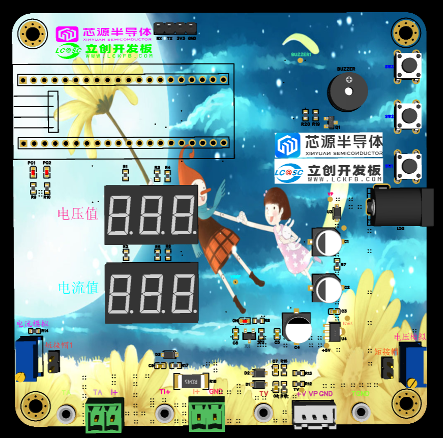
Physical Object Display,
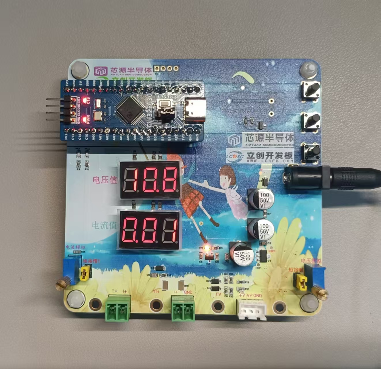
Physical Debugging Verification Images:
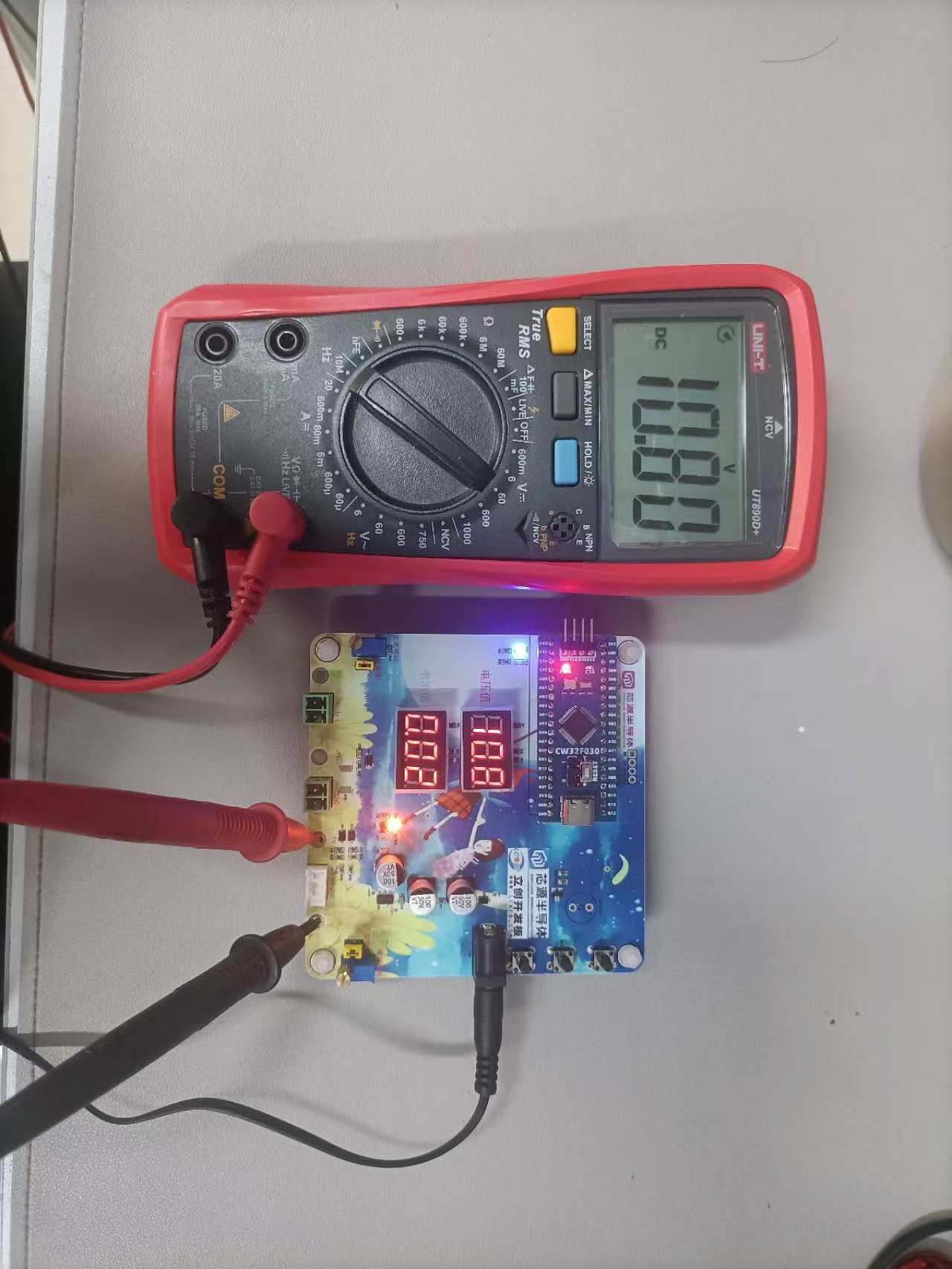
From the physical debugging images, the open-source test shows that the measurement accuracy is quite high.
Bilibili Demo Video: LCSC Development Board Training Camp Homework Submission - CW32 Voltage and Current Meter


 京公网安备 11010802033920号

 FU-68PDF-V510M106B


