Overview:
When it comes to tinkering with electronics, what could be a better design than A Certain Scientific Railgun? The deeply customized "Toaru Kagaku no Voltmeter & Ammeter (CW32)" logo and Misaka Mikoto's cool discharge pose form the soul of this design. Considering economic factors, multiple versions with different appearances were created (technology is all about reskinning, after all).
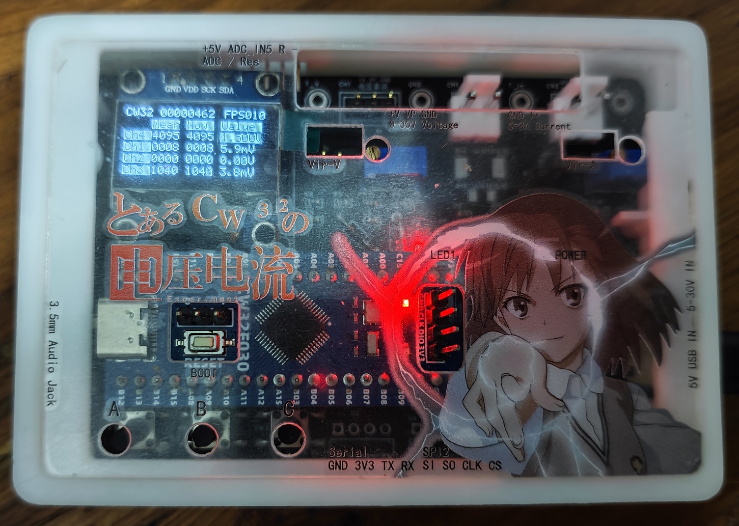
Functionally, it includes voltage and current testing, test value calibration, voltage divider resistance measurement, and a 3.5mm headphone jack. The main considerations for the functional design are:
1. Voltage and current testing and test value calibration are the primary focus, no further explanation needed
. 2. Voltage divider resistance measurement is not very accurate, and the accuracy varies depending on the resistance of the measured object, but its simplicity is a significant advantage, allowing for future expansion with external accessories (such as photodiode probes for illuminance, light flicker, UV intensity, etc.).
3. The 3.5mm headphone test includes headphone open detection, button function detection, and Standard (US standard)/OMTP wiring sequence detection. The principle is relatively simple, but I haven't seen anything similar before, and this is the function I most wanted to implement in this project.
Operationally, key1 switches the calibration channel, key2 calibrates, and key3 switches the mode (test mode switching and calibration Y-value switching are multiplexed), see the flowchart below:

The exterior design
was done quickly using LCSC EDA; although there are some flaws in the design due to my novice approach, it's generally without major issues.
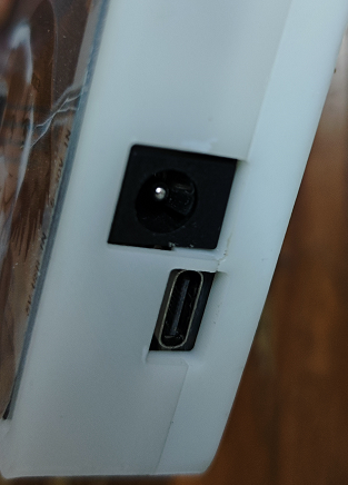
Besides the front opening, the sides also feature a rich array of interfaces: a DC port, USB power port, 5V/3.3V/ADC/resistance measurement/SPI/serial port, and even a 3.5mm headphone jack for testing 3.5mm headphones!
Features:
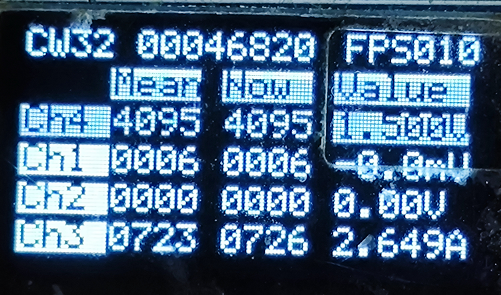
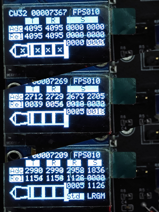
1. Simultaneous acquisition and reading of all four channels of the CW32 ADC conversion sequence;
2. Simultaneous display of ADC average value, instantaneous value, and calibrated measurement value on one screen for easy debugging and confirmation;
3. Uses inverse colors to mark measurement values approaching or exceeding the range, and uses `-0` to mark measurement values below the calibration lower limit (since the circuit is not designed to read negative voltages, calculating negative values is incorrect);
4. Displays frame sequence and frame rate information;
5. Quick and clear calibration. Use key1 to switch modes (1: Normal; 2: 3V voltage range; 3: 30V voltage range; 4: Current; 5: Display current in voltage reading mode), and key3 to switch calibration points; pressing key2 during calibration directly sets the ADC successfully and displays the new value; the mode, calibration x, and calibration y are displayed on the left, middle, and right respectively, connected by an equal sign, which is very intuitive.
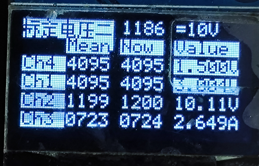
(Measurement values are updated in real time after pressing key2)

6. Resistance measurement function (illustrated as connected resistor/open/short)

6. 3.5mm headphone electrical test (illustrated as headphone not inserted/inserted/in-line control button pressed), which determines whether the headphone is inserted, whether the audio unit is disconnected, the headphone button is pressed, and whether the headphone contains a microphone by applying DC level to the headphone. The parts that are the same as in the headphone wiring standard
circuit design
example tutorial will not be repeated. The main adjustments are as follows:
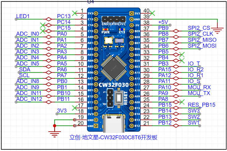
1. Use an I2C OLED screen to enrich the content display and debugging, while saving a lot of I/O, thus giving the opportunity to bring out other function pins
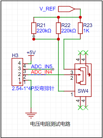
. 2. In addition to voltage measurement, current measurement, and reference voltage measurement, it adds direct reading of values without voltage divider ADC and resistance measurement by series resistor voltage divider method (in fact, the resistor I soldered used 100k/510ohm, which is different from the schematic diagram. Note that the resistance constant in the code needs to be modified).
Since resistance measurement requires power supply to the device, considering the power consumption, the supply voltage cannot be too high. Therefore, without adding an amplifier circuit, Unlike voltage measurement circuits, which can use two ADCs simultaneously, this circuit cannot. The simplest method is to use a switch to change the series voltage divider resistors and manually read the resistance value corresponding to the current voltage divider resistor. Of course, for further improvement, an analog switch chip could be used for control, or a GPIO comparison method could be used to sense the currently selected voltage divider resistor. However, the current solution is acceptable; after all, even the 10x probe of an oscilloscope is manually set. The voltage divider method for measuring resistance is essentially a reserve for future photodiode probes.
Later testing revealed that direct resistance measurement has some fluctuations, requiring circuit modification to add a filter capacitor to the ADC.
3. A 3.5mm headphone test circuit was designed, which can be used to test headphone disconnection, 4-segment headphone design, and in-line control button functionality. The schematic uses a direct labeling of the network lines, omitting the network output labels of the four ADCs. The

test principle references the Android 3.5mm Headphones: Accessory Specifications.
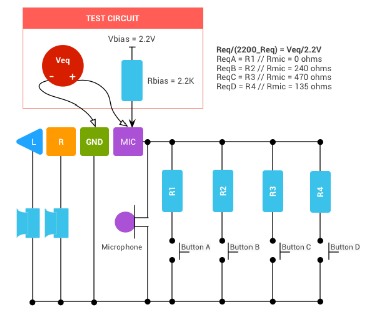
This function was only roughly estimated for feasibility during the circuit design phase; detailed functional design was not performed. Testing and verification relied on algorithm-controlled GPIO output high and low levels. Each of the four GPIOs is connected in series with a 2.2k resistor for voltage division, and the symmetrical circuit facilitates comparison and calculation. This approach improves design efficiency while preserving verification and adjustment space.
The design is based on worst-case analysis:
a. GPIO current estimation: With a 3.3V input to a functional headphone, each terminal connected in series with a 2.2k resistor, an output current less than 1.5mA is safe.
b. Audio unit power consumption estimation: When the audio unit resistance is higher than 1kΩ, the power consumption u^2/r of the test circuit
has been verified using physical testing. A method was used where t and r1 output high levels, and r2 and s output low levels. An ADC was used to read the voltage of each 2.2k resistor at once, and the headphone's voltage was directly compared to the ADC readings to determine its performance.
The test principle is simplified as follows:

Due to the unstable power supply voltage, the output voltage itself fluctuates; the ADC also lacks a filter capacitor, resulting in large fluctuations in the acquired data, which is not aesthetically pleasing. The circuit can be adjusted as follows (however, current tests show stable and fast judgment, so it can be left unchanged):
Change IO_T/IO_R1 to a separate LDO, change IO_R2 and IO_S to direct grounding,
and add a filter capacitor to the ADC pin.
4. Connect the USB via a diode to avoid backflow current from the USB when both the DC plug and USB are plugged in simultaneously, which could damage the device.

Program Design:
1. After debugging and verification, it was found that the OLED screen refresh rate is slow (soft I2C refreshes the entire screen each time, with a frame rate of 10fps), and this refresh rate is still readable by the human eye. Therefore, the program is designed so that the main function refreshes the display content at full speed, and each loop acquires ADC information and draws the entire screen.
2. Use a timer to acquire ADC data (4 channels) every 1ms and simultaneously read the button status from the digital channels. Use IF conditions and mode variables to determine whether to switch the working ADC (CW32 conversion sequence has a maximum of 4 channels, this project uses 8 channels, so channel switching is necessary), adjust GPIO output, and save calibration parameters.
3. Use multi-segment function calibration, including 0 and 1. Since there is no function to measure negative voltage, when the ADC reading is below 0, it displays -0.
// The calibrated y value u8 *adj_names[][4] = { { (uint8_t*)"=0mV", (uint8_t*)"=500mV", (uint8_t*)"=1.0V", (uint8_t*)"=2.5V" }, { (uint8_t*)"=0V", (uint8_t*)"=1V", (uint8_t*)"=10V", (uint8_t*)"=20V" }, { (uint8_t*)"=0mA", (uint8_t*)"=500mA", (uint8_t*)"=1.5A", (uint8_t*)"=3A" }, { (uint8_t*)"=0mV", (uint8_t*)"=50mV", (uint8_t*)"=150mV", (uint8_t*)"=300mV" },};
A straight line is fitted using two coordinate points (x1, y1) and (x2, y2). The calib value is converted to SI units using the calibration value.
float calib_value(uint16_t adc, uint16_t next_cali_index, float y1, float y2 ) { return (y2 - y1) * (adc - cali[next_cali_index - 1]) / (cali[next_cali_index] - cali[next_cali_index - 1]) + y1;}
4. Test values are automatically converted to mKM units based on their magnitude, and significant digits are retained according to the test precision. To avoid test values exceeding the range, the test results are displayed in reverse color when approaching the upper limit.
5. Calibration. The number of data points was changed to 13, and the calibration value was read directly from the global variable array during the calibration reading process. The calibration saving function was changed to read the calibration value from the flash memory again after saving to ensure the validity of the saved value.
// Read calibration results void read_vol_cur_calibration(void){ flash_read(0, cali, 13);
if(cali[0] != 0x88) // Calculate the theoretical value and store it before calibration { cali[1] = 0; cali[2] = 4096 * 0.5 / 3; cali[3] = 4096 / 3; cali[4] = 4096 * 2.5 / 3; cali[5] = 0; cali[6] = 4096 / 1.5 / 23; cali[7] = 4096 * 10 / 1.5 / 23; cali[8] = 4096 * 20 / 1.5 / 23; cali[9] = 0; cali[10] = 4096 * 50 / 1500; cali[11] = 4096 * 150 / 1500; cali[12] = 4096 * 300 / 1500; }}
// Save calibration results void save_calibration(void){ cali[0] = 0x88; flash_erase(); flash_write(0, cali, 13); read_vol_cur_calibration();}


 京公网安备 11010802033920号

 1N5264D-BP


