Update Log
2024/08/23: Added a PCB design with a patch antenna version; currently undergoing board fabrication and verification.
Introduction:
I've always wanted to make a tri-mode keyboard, but the USB receiver has always been a major challenge. Either the size couldn't be made too small, or there was a lack of development resources, or it was even impossible to develop. By chance, I saw an open-source TP78 keyboard on LCSC that used a CH582M tri-mode receiver, so I wanted to replicate it. The board was double-sided surface mount, but my soldering skills are too poor, and after scrapping five PCBs, I gave up on this approach. Searching on the WCH website, I found that the CH582 has a slightly smaller QFN28 package, so I tried to redesign a receiver using the CH582F. To make soldering easier for those with poor soldering skills and increase the success rate of replication, I simplified some peripheral circuitry, making all components single-sided, easily achievable with a teppanyaki grill. I will use this design as a tri-mode receiver to complete my tri-mode keyboard project, and I may also use it as a transmitter to implement a wireless debugger and other projects.
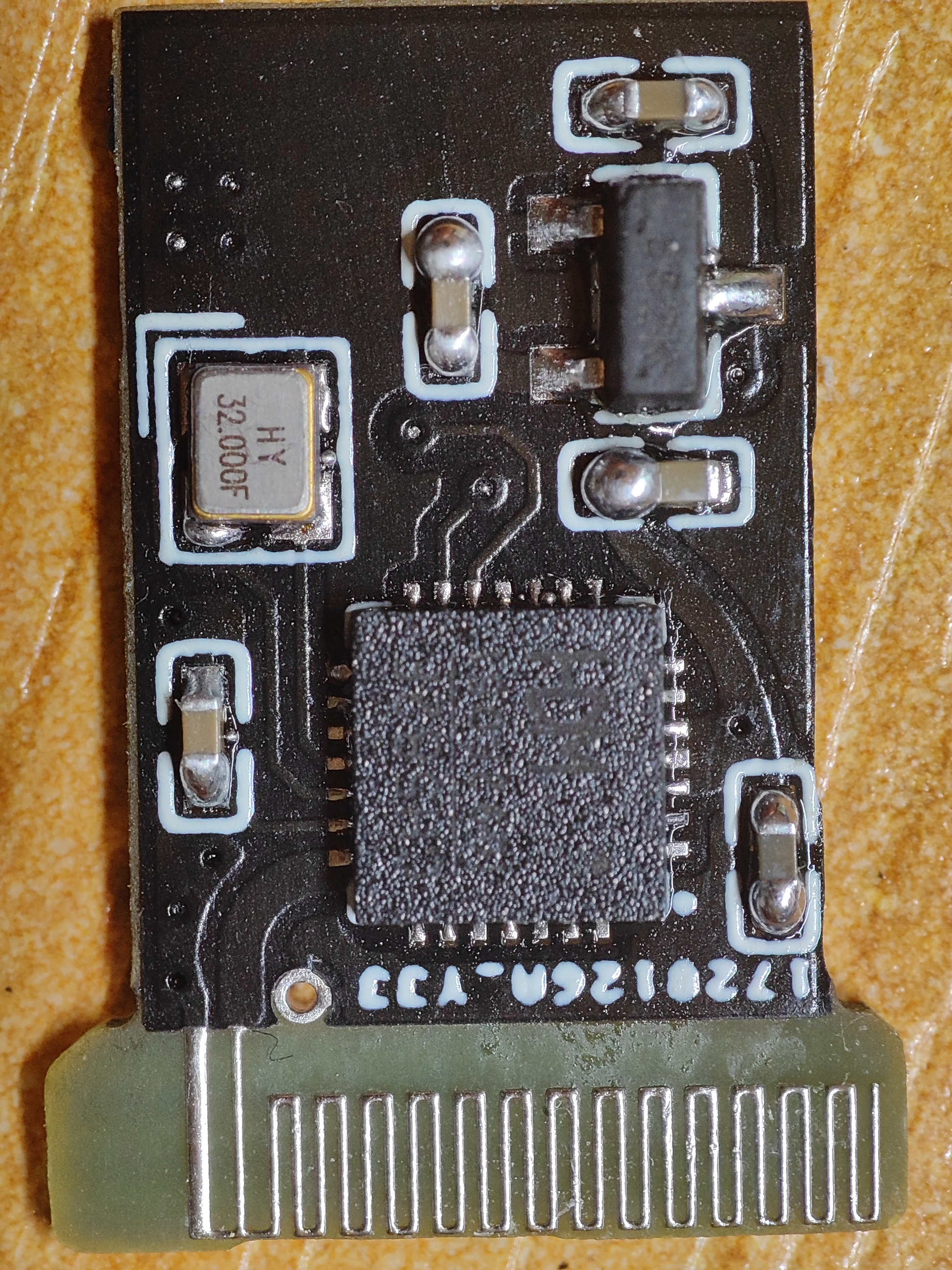
(Please be gentle with your soldering, the soldering is quite ugly.)
Basic Information:
Main controller CH582F;
External high-speed 32MHz crystal oscillator; Recommended parameters: 12pF, accuracy 10ppm or better. You can directly order the BOM exported by LCSC.
Antenna: Uses onboard antenna; Package provided by the WCH official community; Impedance matching has been done according to design requirements. Note that you must choose a 0.8mm thickness for the PCB; otherwise, the impedance will be incorrect, and you won't be able to fit it into the casing.
Casing: Search for "USB receiver casing" on Taobao. It is recommended to buy a casing from CERNET Corporation, as the PCB is designed based on CERNET's casing dimensions and cannot guarantee complete compatibility with other manufacturers' casing sizes.
Regarding the main controller
, here's why we didn't use the CH591D. Some might say that this chip has a smaller package and supports BLE 5.4, so wouldn't it be more suitable? I did consider using this chip in the initial design phase, but I later learned from a BSP developer that the CH591D chip doesn't fully support BLE 5.4 and has removed a lot of peripherals (although as a receiver/transmitter, I don't need most of them). This meant that the CH591D couldn't completely copy the CH582D tutorials during some development, and I had to refer to the manual and make corresponding modifications. Since there's no substantial difference in speed and latency between BLE 5.4 (referring specifically to the CH591D's Bluetooth) and BLE 5.3, and the size isn't a problem, why not choose the CH582F, which has more documentation available?
There's another reason: currently (as of June 14, 2024), only one seller on Taobao, Ruiling Electronics, sells the CH591D, while the CH582F is available from multiple stores, including Uxin and LCSC.
Regarding the antenna
, let me briefly mention the onboard antenna design. The antenna package here comes from the Bluetooth antenna layout and design reference on the WCH official community. As you can see from the comments, this package isn't the best performing solution. Impedance matching comes from the CH57x/CH58x schematic and PCB design blog. Since the CH582F chip already has a built-in Π circuit, the antenna requirements for this project aren't high, so a direct connection of the ANT pin to the antenna PCB was used. Signal strength was excellent within 10m. If there are future signal requirements, I might consider designing a solution using a ceramic chip (procrastination).
For the replica
PCB, please be sure to select a 0.8mm board thickness and ignore DRC errors (onboard antenna). The BOM has been matched; you can order directly from the exported list.
Design Issues:
Due to insufficient consideration during the design phase, the onboard antenna is too close to the board frame. JLCPCB's process limitations mean there's a possibility the antenna might break. I received 7 boards after prototyping, and one of them had this problem. It can be resolved by slightly shifting the entire board to the left. Both the unshifted and shifted designs have been uploaded to oshwhub. Note: I have only tested the unshifted version; the shifted version has not been tested. Please consider this before prototyping.
Regarding debugging:
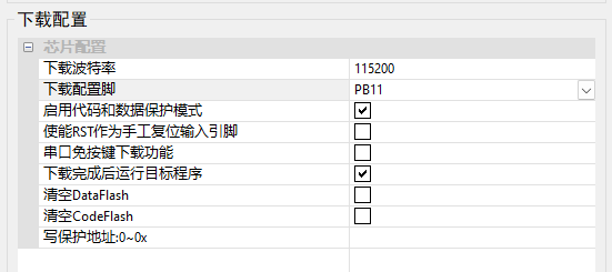
Due to the casing, the boot pin button cannot be directly routed from the chip. Therefore, BOOT0 (PB22) is pulled low on the PCB, allowing the chip to directly enter USB programming mode upon power-up. WCHISPTool can be used for programming. During programming, the download configuration pin is configured as BOOT1 (PB11/USB1 DP) so the chip can directly enter the program later. When a second programming is required, USB DP can be pulled up to enter USB programming mode. The WCHISPTool programming configuration is as follows:
CH582 boot logic: If the chip is a blank chip (a newly purchased chip or one that has been burned and cleared from flash), it will directly enter programming mode; otherwise, it will check whether BOOT0 (PB22) is pulled down upon power-up. If it is pulled down, it will enter programming mode. After configuring the download configuration pin, it will change to check the download configuration pin to determine whether to enter programming mode.
Regarding open source
, I am a computer science student and have not systematically studied hardware design. This design was created after reading online reference materials, so I cannot guarantee that the design will run perfectly. If you encounter any bugs, please point them out; I am willing to learn humbly.
This project will be open source under the GPLv3 license, and any student is welcome to make modifications.


 京公网安备 11010802033920号

 ASDX030D44D


